
Owner's Manual
Page 2
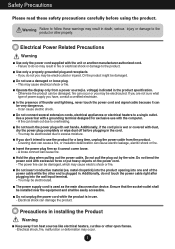
... signal cable because it cannot come loose. - Do not connect several extension cords, electrical appliances or electrical heaters to do not touch the power cable right after plugging into one end of power supply you may be damaged, which may result in death, serious product or other open flames. - If you don't intend to the Electrical Power Related Precautions Warning Use only the power cord supplied...
... signal cable because it cannot come loose. - Do not connect several extension cords, electrical appliances or electrical heaters to do not touch the power cable right after plugging into one end of power supply you may be damaged, which may result in death, serious product or other open flames. - If you don't intend to the Electrical Power Related Precautions Warning Use only the power cord supplied...
Owner's Manual
Page 3
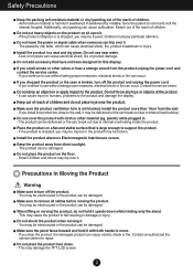
... product is broken, turn off the product and unplug the power cord. - Keep the product away from the wall. - Precautions in damage or injury. You may be electrocuted or the product can trip over it upside down . - This may damage the TFT-LCD screen. 2 Do not shock the product when moving it . - Make sure the panel faces forward and hold...
... product is broken, turn off the product and unplug the power cord. - Keep the product away from the wall. - Precautions in damage or injury. You may be electrocuted or the product can trip over it upside down . - This may damage the TFT-LCD screen. 2 Do not shock the product when moving it . - Make sure the panel faces forward and hold...
Owner's Manual
Page 4
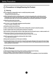
... a comfortable and natural position when working with a product to relax the muscles. Do not press on it. Make sure to use chemicals such as nail, pencil or pen, or make a scratch on the panel with a wet cloth. Fire or electric shock accident can occur. Safety Precautions Precautions in and related problems are not covered by referring to the User's Guide. -
... a comfortable and natural position when working with a product to relax the muscles. Do not press on it. Make sure to use chemicals such as nail, pencil or pen, or make a scratch on the panel with a wet cloth. Fire or electric shock accident can occur. Safety Precautions Precautions in and related problems are not covered by referring to the User's Guide. -
Owner's Manual
Page 5
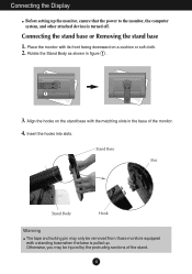
..., and other attached devices is turned off. Stand Base Slot Stand Body Hook Warning The tape and locking pin may be removed from those monitors equipped with the matching slots in figure 1 . 1 3. Align the hooks on a cushion or soft cloth. 2. Rotate the Stand Body as shown in the base of the stand. 4 Connecting the stand base or Removing the stand base 1. Insert the hooks into slots. Connecting the Display Before setting up .
..., and other attached devices is turned off. Stand Base Slot Stand Body Hook Warning The tape and locking pin may be removed from those monitors equipped with the matching slots in figure 1 . 1 3. Align the hooks on a cushion or soft cloth. 2. Rotate the Stand Body as shown in the base of the stand. 4 Connecting the stand base or Removing the stand base 1. Insert the hooks into slots. Connecting the Display Before setting up .
Owner's Manual
Page 6
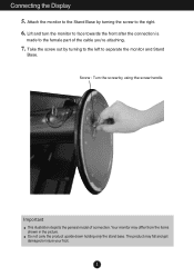
Attach the monitor to the Stand Base by turning to the left to separate the monitor and Stand Base. Take the screw out by turning the screw to the female part of connection. Connecting the Display 5. Screw : Turn the screw by using the screw handle. The product may differ from the items shown in the picture. Your monitor may fall and get damaged or injure your foot. 5 Lift and turn the monitor to face...
Attach the monitor to the Stand Base by turning to the left to separate the monitor and Stand Base. Take the screw out by turning the screw to the female part of connection. Connecting the Display 5. Screw : Turn the screw by using the screw handle. The product may differ from the items shown in the picture. Your monitor may fall and get damaged or injure your foot. 5 Lift and turn the monitor to face...
Owner's Manual
Page 7
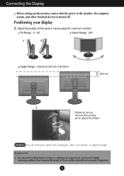
... power to the monitor, the computer system, and other attached devices is turned off. Positioning your display 1. Ergonomic It is removed, to adjust its height. Connecting the Display Before setting up the monitor, ensure that in order to maintain an ergonomic and comfortable viewing position, the forward tilt angle of the panel in various ways for maximum comfort. Tilt Range : -5˚~20˚ Swivel Range : 350˚ Height Range : maximun 3.94 inch...
... power to the monitor, the computer system, and other attached devices is turned off. Positioning your display 1. Ergonomic It is removed, to adjust its height. Connecting the Display Before setting up the monitor, ensure that in order to maintain an ergonomic and comfortable viewing position, the forward tilt angle of the panel in various ways for maximum comfort. Tilt Range : -5˚~20˚ Swivel Range : 350˚ Height Range : maximun 3.94 inch...
Owner's Manual
Page 9
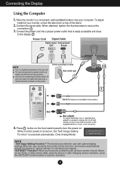
...letters, screen flicker or tilted screen while using the device or after changing screen resolution, press the AUTO/SET function button to the display. 2 Power Cord Signal Cable Digital signal Analog signal DVI D-sub NOTE This is executed automatically. (Only Analog Mode) NOTE ' Self Image Setting Function'? Press button on the supplied cable to optimal settings for the product. When monitor power is turned on top of the rear view. Connect the signal cable. Connecting the Display Using the Computer 1. Place the monitor in all countries.) PC MAC Mac adapter For...
...letters, screen flicker or tilted screen while using the device or after changing screen resolution, press the AUTO/SET function button to the display. 2 Power Cord Signal Cable Digital signal Analog signal DVI D-sub NOTE This is executed automatically. (Only Analog Mode) NOTE ' Self Image Setting Function'? Press button on the supplied cable to optimal settings for the product. When monitor power is turned on top of the rear view. Connect the signal cable. Connecting the Display Using the Computer 1. Place the monitor in all countries.) PC MAC Mac adapter For...

Owner's Manual
Page 11
... to select or adjust functions in the On Screen Display. The message "OSD UNLOCKED" should appear. The default setting is used when two computers are connected to the display. OSD LOCKED/UNLOCKED This function allows you to lock the current control settings, so that they cannot be inadvertently changed. The message "OSD LOCKED" should appear. - + Buttons Use these buttons to page 17. Control Panel Functions Front Panel Controls Control Function MENU Button Use this button to make D-Sub or DVI connector active. This feature...
... to select or adjust functions in the On Screen Display. The message "OSD UNLOCKED" should appear. The default setting is used when two computers are connected to the display. OSD LOCKED/UNLOCKED This function allows you to lock the current control settings, so that they cannot be inadvertently changed. The message "OSD LOCKED" should appear. - + Buttons Use these buttons to page 17. Control Panel Functions Front Panel Controls Control Function MENU Button Use this button to make D-Sub or DVI connector active. This feature...
Owner's Manual
Page 12
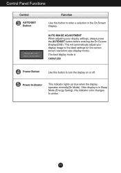
... best display mode is in the On Screen Display. This will automatically adjust your display settings, always press the AUTO/SET button before entering the On Screen Display(OSD). Power Indicator This Indicator lights up blue when the display operates normally(On Mode). AUTO IMAGE ADJUSTMENT When adjusting your display image to enter a selection in Sleep Mode (Energy Saving), this indicator color changes to turn the display on or off. Control Panel Functions Control AUTO/SET Button Function Use this button to the ideal settings for the current screen resolution size (display...
... best display mode is in the On Screen Display. This will automatically adjust your display settings, always press the AUTO/SET button before entering the On Screen Display(OSD). Power Indicator This Indicator lights up blue when the display operates normally(On Mode). AUTO IMAGE ADJUSTMENT When adjusting your display image to enter a selection in Sleep Mode (Energy Saving), this indicator color changes to turn the display on or off. Control Panel Functions Control AUTO/SET Button Function Use this button to the ideal settings for the current screen resolution size (display...
Owner's Manual
Page 13
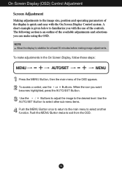
... the OSD appears. To access a control, use of the display is given below to familiarize you want becomes highlighted, press the AUTO/SET Button. Push the MENU Button twice to select another function. A short example is quick and easy with the On Screen Display Control system. On Screen Display (OSD) Control Adjustment Screen Adjustment Making adjustments to the image size, position and operating parameters of the controls. Use the AUTO/SET Button to select other sub-menu items. Push the MENU Button once...
... the OSD appears. To access a control, use of the display is given below to familiarize you want becomes highlighted, press the AUTO/SET Button. Push the MENU Button twice to select another function. A short example is quick and easy with the On Screen Display Control system. On Screen Display (OSD) Control Adjustment Screen Adjustment Making adjustments to the image size, position and operating parameters of the controls. Use the AUTO/SET Button to select other sub-menu items. Push the MENU Button once...
Owner's Manual
Page 14
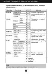
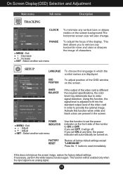
...-menu A D Reference PICTURE BRIGHTNESS CONTRAST GAMMA To adjust the brightness, contrast and gamma of the screen COLOR PRESET RED sRGB 6500K 9300K GREEN BLUE POSITION HORIZONTAL VERTICAL TRACKING CLOCK PHASE To customize the color of the screen To adjust the position of the screen To improve the clarity and stability of the screen SETUP LANGUAGE OSD HORIZONTAL POSITION VERTICAL To customize the screen status for a user's operating environment WHITE BALANCE POWER INDICATOR FACTORY RESET FLATRON MOVIE / TEXT F-ENGINE(- ) USER NORMAL To select or customize desired image...
...-menu A D Reference PICTURE BRIGHTNESS CONTRAST GAMMA To adjust the brightness, contrast and gamma of the screen COLOR PRESET RED sRGB 6500K 9300K GREEN BLUE POSITION HORIZONTAL VERTICAL TRACKING CLOCK PHASE To customize the color of the screen To adjust the position of the screen To improve the clarity and stability of the screen SETUP LANGUAGE OSD HORIZONTAL POSITION VERTICAL To customize the screen status for a user's operating environment WHITE BALANCE POWER INDICATOR FACTORY RESET FLATRON MOVIE / TEXT F-ENGINE(- ) USER NORMAL To select or customize desired image...
Owner's Manual
Page 15
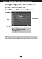
On Screen Display(OSD) Selection and Adjustment You were introduced to the procedure of the OSD appears. Menu Name PICTURE Icons Sub-menus Button Tip MENU : Exit - + : Adjust (Decrease/Increase) SET : Enter : Select another sub-menu NOTE OSD (On Screen Display) menu languages on the Menu. Press the MENU Button, then the main menu of selecting and adjusting an item using the OSD system. Listed below are the icons, icon names, and icon descriptions of the all items shown on the monitor may differ from the manual. 14
On Screen Display(OSD) Selection and Adjustment You were introduced to the procedure of the OSD appears. Menu Name PICTURE Icons Sub-menus Button Tip MENU : Exit - + : Adjust (Decrease/Increase) SET : Enter : Select another sub-menu NOTE OSD (On Screen Display) menu languages on the Menu. Press the MENU Button, then the main menu of selecting and adjusting an item using the OSD system. Listed below are the icons, icon names, and icon descriptions of the all items shown on the monitor may differ from the manual. 14
Owner's Manual
Page 16
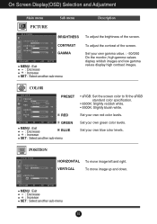
...: Set the screen color to fit the sRGB standard color specification. • 6500K: Slightly reddish white. • 9300K: Slightly bluish white. RED Set your own blue color levels. GREEN MENU : Exit +- : Decrease : Increase BLUE SET : Select another sub-menu Set your own gamma value. : -50/0/50 On the monitor, high gamma values display whitish images and low gamma values display high contrast images. CONTRAST GAMMA MENU : Exit +- : Decrease : Increase SET : Select another sub-menu 15 POSITION POSITION HORIZONTAL VERTICAL To move image...
...: Set the screen color to fit the sRGB standard color specification. • 6500K: Slightly reddish white. • 9300K: Slightly bluish white. RED Set your own blue color levels. GREEN MENU : Exit +- : Decrease : Increase BLUE SET : Select another sub-menu Set your own gamma value. : -50/0/50 On the monitor, high gamma values display whitish images and low gamma values display high contrast images. CONTRAST GAMMA MENU : Exit +- : Decrease : Increase SET : Select another sub-menu 15 POSITION POSITION HORIZONTAL VERTICAL To move image...
Owner's Manual
Page 17
... the factory default settings. If this function when white and black colors are displayed. SETUP SETUP MENU - SETUP + SET LANGUAGE OSD POSITION To choose the language in which the control names are present in the screen. If you set ON at any time, the power indicator will go off. WHITE BALANCE If the output of the video card is different the required specifications, the color level may deteriorate due to reset immediately. If you to remove any vertical...
... the factory default settings. If this function when white and black colors are displayed. SETUP SETUP MENU - SETUP + SET LANGUAGE OSD POSITION To choose the language in which the control names are present in the screen. If you set ON at any time, the power indicator will go off. WHITE BALANCE If the output of the video card is different the required specifications, the color level may deteriorate due to reset immediately. If you to remove any vertical...
Owner's Manual
Page 18
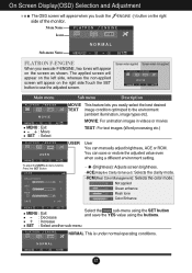
... images (Word processing etc.) USER User You can save the YES value using a different environment setting. To adjust the USER sub-menu function, Press the SET Button USER BRIGHTNESS ACE 1 RCM 2 SAVE ... (Brightness): Adjusts screen brightness. ...ACE(Adaptive Clarity Enhancer): Selects the clarity mode. ...RCM(Real Color Management): Selects the color mode. 0 Not applied 1 Green enhance 2 Flesh tone 3 Color Enhance MENU SET MENU : Exit +- : Decrease : Increase Select the SAVE sub-menu using the SET button and save or restore the adjusted value even when using the buttons. SET...
... images (Word processing etc.) USER User You can save the YES value using a different environment setting. To adjust the USER sub-menu function, Press the SET Button USER BRIGHTNESS ACE 1 RCM 2 SAVE ... (Brightness): Adjusts screen brightness. ...ACE(Adaptive Clarity Enhancer): Selects the clarity mode. ...RCM(Real Color Management): Selects the color mode. 0 Not applied 1 Green enhance 2 Flesh tone 3 Color Enhance MENU SET MENU : Exit +- : Decrease : Increase Select the SAVE sub-menu using the SET button and save or restore the adjusted value even when using the buttons. SET...
Owner's Manual
Page 19
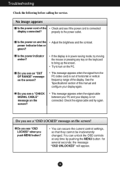
... screen? You can unlock the OSD controls at any key on the keyboard to turn on the PC. Troubleshooting Check the following before calling for several seconds: the message "OSD UNLOCKED" will appear. 18 No image appears Is the power cord of this manual and configure your display is in power saving mode, try again. Do you see a "CHECK SIGNAL CABLE" message on and the power indicator blue or green? Adjust the brightness and the contrast...
... screen? You can unlock the OSD controls at any key on the keyboard to turn on the PC. Troubleshooting Check the following before calling for several seconds: the message "OSD UNLOCKED" will appear. 18 No image appears Is the power cord of this manual and configure your display is in power saving mode, try again. Do you see a "CHECK SIGNAL CABLE" message on and the power indicator blue or green? Adjust the brightness and the contrast...
Owner's Manual
Page 20
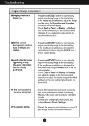
... V position icon in the slot. Check Control Panel --> Display --> Settings and adjust the display to the recommended resolution or adjust the display image to the ideal setting. Settings. On the screen background, vertical bars or stripes are not clearly portrayed. Set the color setting higher than 24 bits (true color) at Control Panel - Press the AUTO/SET button to automatically adjust your display image to the ideal setting. Check Control Panel --> Display --> Settings and see if the frequency or the resolution were changed. If yes, readjust the video card...
... V position icon in the slot. Check Control Panel --> Display --> Settings and adjust the display to the recommended resolution or adjust the display image to the ideal setting. Settings. On the screen background, vertical bars or stripes are not clearly portrayed. Set the color setting higher than 24 bits (true color) at Control Panel - Press the AUTO/SET button to automatically adjust your display image to the ideal setting. Check Control Panel --> Display --> Settings and see if the frequency or the resolution were changed. If yes, readjust the video card...
Owner's Manual
Page 21
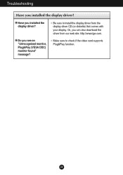
Be sure to check if the video card supports Plug&Play function. 20 Make sure to install the display driver from our web site: http://www.lge.com. Troubleshooting Have you see an "Unrecognized monitor, Plug&Play (VESA DDC) monitor found" message? Do you installed the display driver? Or, you installed the display driver? Have you can also download the driver from the display driver CD (or diskette) that comes with your display.
Be sure to check if the video card supports Plug&Play function. 20 Make sure to install the display driver from our web site: http://www.lge.com. Troubleshooting Have you see an "Unrecognized monitor, Plug&Play (VESA DDC) monitor found" message? Do you installed the display driver? Or, you installed the display driver? Have you can also download the driver from the display driver CD (or diskette) that comes with your display.
Owner's Manual
Page 22
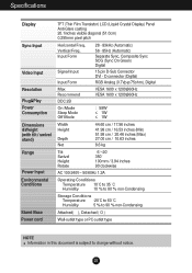
... (with tilt / swivel stand) Range Power Input Environmental Conditions Stand Base Power cord TFT (Thin Film Transistor) LCD (Liquid Crystal Display) Panel Anti-Glare coating 20.1inches visible diagonal (51.0cm) 0.255mm pixel pitch Horizontal Freq. Input Form Signal Input Input Form 28 - 83kHz (Automatic) 56 - 85Hz (Automatic) Separate Sync, Composite Sync SOG (Sync On Green) Digital 15 pin D-Sub Connector DVI - D connector (Digital) RGB Analog (0.7Vp-p/75ohm), Digital Max Recommend VESA 1600 x 1200@60Hz VESA 1600 x 1200@60Hz DDC 2B On Mode Sleep Mode Off Mode...
... (with tilt / swivel stand) Range Power Input Environmental Conditions Stand Base Power cord TFT (Thin Film Transistor) LCD (Liquid Crystal Display) Panel Anti-Glare coating 20.1inches visible diagonal (51.0cm) 0.255mm pixel pitch Horizontal Freq. Input Form Signal Input Input Form 28 - 83kHz (Automatic) 56 - 85Hz (Automatic) Separate Sync, Composite Sync SOG (Sync On Green) Digital 15 pin D-Sub Connector DVI - D connector (Digital) RGB Analog (0.7Vp-p/75ohm), Digital Max Recommend VESA 1600 x 1200@60Hz VESA 1600 x 1200@60Hz DDC 2B On Mode Sleep Mode Off Mode...
Owner's Manual
Page 24
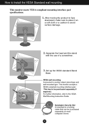
... (stand type and wall-mounted type. Separate the head and the stand with the use of a screwdriver. 3. This monitor accepts a VESA-compliant mounting interface pad.This has to be purchased separately at most computer stores 23 After moving the product to face downward, make sure to place it on a soft cloth or a cushion to the VESA Wall Mounting Instruction Guide. Kensington Security Slot Connected to a locking cable...
... (stand type and wall-mounted type. Separate the head and the stand with the use of a screwdriver. 3. This monitor accepts a VESA-compliant mounting interface pad.This has to be purchased separately at most computer stores 23 After moving the product to face downward, make sure to place it on a soft cloth or a cushion to the VESA Wall Mounting Instruction Guide. Kensington Security Slot Connected to a locking cable...


