
Owner's Manual
Page 5
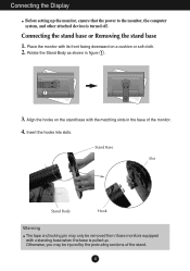
Rotate the Stand Body as shown in the base of the stand. 4 Otherwise, you may only be injured by the protruding sections of the monitor. 4. Connecting the stand base or Removing the stand base 1. Insert the hooks into slots. Align the hooks on the stand base with its front facing... downward on a cushion or soft cloth. 2. Place the monitor with the matching slots in figure 1 . 1 3. Stand Base Slot Stand Body Hook Warning The tape and locking pin may be removed from those...
Rotate the Stand Body as shown in the base of the stand. 4 Otherwise, you may only be injured by the protruding sections of the monitor. 4. Connecting the stand base or Removing the stand base 1. Insert the hooks into slots. Align the hooks on the stand base with its front facing... downward on a cushion or soft cloth. 2. Place the monitor with the matching slots in figure 1 . 1 3. Stand Base Slot Stand Body Hook Warning The tape and locking pin may be removed from those...
Owner's Manual
Page 6
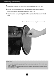
... the Stand Base by turning the screw to separate the monitor and Stand Base. Do not carry the product upside down holding only the stand base. Screw : Turn the screw by turning to the left to ... This illustration depicts the general model of the cable you're attaching. 7. Take the screw out by using the screw handle. Lift and turn the monitor to face towards the front after the connection is made to the female part of connection. Your...
... the Stand Base by turning the screw to separate the monitor and Stand Base. Do not carry the product upside down holding only the stand base. Screw : Turn the screw by turning to the left to ... This illustration depicts the general model of the cable you're attaching. 7. Take the screw out by using the screw handle. Lift and turn the monitor to face towards the front after the connection is made to the female part of connection. Your...
Owner's Manual
Page 7
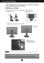
... It is recommended that the power to maintain an ergonomic and comfortable viewing position, the forward tilt angle of the monitor should not exceed 5 degrees. 6 Connecting the Display Before setting up the monitor, ensure that in various ways for maximum comfort. Notice You do not need to replace the Locking pin after....0mm) 100.0 mm * Please be sure to remove the Locking pin to adjust its height. Adjust the position of the panel in order to the monitor, the computer system, and other attached devices is removed, to adjust the height.
... It is recommended that the power to maintain an ergonomic and comfortable viewing position, the forward tilt angle of the monitor should not exceed 5 degrees. 6 Connecting the Display Before setting up the monitor, ensure that in various ways for maximum comfort. Notice You do not need to replace the Locking pin after....0mm) 100.0 mm * Please be sure to remove the Locking pin to adjust its height. Adjust the position of the panel in order to the monitor, the computer system, and other attached devices is removed, to adjust the height.

Owner's Manual
Page 8
If the monitor head touches the Stand Base, then the Stand Base could crack. For detailed information, please refer to access the Pivot function. Connecting the Display Using the Pivot function 1. Please be cautious and avoid contact between the monitor head and the Stand Base when rotating the screen to the Pivot Software CD provided. 7 Head section Stand section 3. Landscape & Portrait : You can rotate the panel 90o clockwise. Lift the monitor to its highest height to utilize the Pivot function. 2.
If the monitor head touches the Stand Base, then the Stand Base could crack. For detailed information, please refer to access the Pivot function. Connecting the Display Using the Pivot function 1. Please be cautious and avoid contact between the monitor head and the Stand Base when rotating the screen to the Pivot Software CD provided. 7 Head section Stand section 3. Landscape & Portrait : You can rotate the panel 90o clockwise. Lift the monitor to its highest height to utilize the Pivot function. 2.
Owner's Manual
Page 9
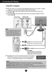
...turned on top of the rear view. Connecting the Display Using the Computer 1. Connect the signal cable. When monitor power is a simplified representation of the stand. 2. your monitor, unlock the stand lock on , the 'Self Image Setting Function' is easily accessible and close to model. ...Macintosh use shielded signal interface cables (Dsub 15 pin cable, DVI cable) with optimal display settings.When the user connects the monitor for the product. Connect the power cord into a proper power outlet that is executed automatically. (Only Analog Mode) NOTE ' Self ...
...turned on top of the rear view. Connecting the Display Using the Computer 1. Connect the signal cable. When monitor power is a simplified representation of the stand. 2. your monitor, unlock the stand lock on , the 'Self Image Setting Function' is easily accessible and close to model. ...Macintosh use shielded signal interface cables (Dsub 15 pin cable, DVI cable) with optimal display settings.When the user connects the monitor for the product. Connect the power cord into a proper power outlet that is executed automatically. (Only Analog Mode) NOTE ' Self ...
Owner's Manual
Page 15
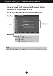
Press the MENU Button, then the main menu of selecting and adjusting an item using the OSD system. Menu Name PICTURE Icons Sub-menus Button Tip MENU : Exit - + : Adjust (Decrease/Increase) SET : Enter : Select another sub-menu NOTE OSD (On Screen Display) menu languages on the Menu. On Screen Display(OSD) Selection and Adjustment You were introduced to the procedure of the OSD appears. Listed below are the icons, icon names, and icon descriptions of the all items shown on the monitor may differ from the manual. 14
Press the MENU Button, then the main menu of selecting and adjusting an item using the OSD system. Menu Name PICTURE Icons Sub-menus Button Tip MENU : Exit - + : Adjust (Decrease/Increase) SET : Enter : Select another sub-menu NOTE OSD (On Screen Display) menu languages on the Menu. On Screen Display(OSD) Selection and Adjustment You were introduced to the procedure of the OSD appears. Listed below are the icons, icon names, and icon descriptions of the all items shown on the monitor may differ from the manual. 14
Owner's Manual
Page 16
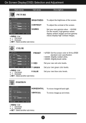
... : Exit +- : Decrease : Increase BLUE SET : Select another sub-menu To adjust the contrast of the screen. Set your own gamma value. : -50/0/50 On the monitor, high gamma values display whitish images and low gamma values display high contrast images. Set your own blue color levels. POSITION POSITION HORIZONTAL VERTICAL To...
... : Exit +- : Decrease : Increase BLUE SET : Select another sub-menu To adjust the contrast of the screen. Set your own gamma value. : -50/0/50 On the monitor, high gamma values display whitish images and low gamma values display high contrast images. Set your own blue color levels. POSITION POSITION HORIZONTAL VERTICAL To...
Owner's Manual
Page 17
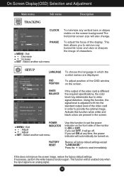
... characters. This item allows you set the power indicator on the screen. To adjust position of the OSD window on the front side of the monitor to set OFF, it will also change. WHITE BALANCE If the output of the video card is adjusted to fit into the standard output level...
... characters. This item allows you set the power indicator on the screen. To adjust position of the OSD window on the front side of the monitor to set OFF, it will also change. WHITE BALANCE If the output of the video card is adjusted to fit into the standard output level...
Owner's Manual
Page 18
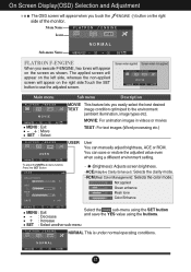
... applied Screen when not applied Main menu Sub menu Description MENU : Exit - , + : Move SET : Select MOVIE This feature lets you touch the side of the monitor. To adjust the USER sub-menu function, Press the SET Button USER BRIGHTNESS ACE 1 RCM 2 SAVE ... (Brightness): Adjusts screen brightness. ...ACE(Adaptive Clarity Enhancer): Selects...
... applied Screen when not applied Main menu Sub menu Description MENU : Exit - , + : Move SET : Select MOVIE This feature lets you touch the side of the monitor. To adjust the USER sub-menu function, Press the SET Button USER BRIGHTNESS ACE 1 RCM 2 SAVE ... (Brightness): Adjusts screen brightness. ...ACE(Adaptive Clarity Enhancer): Selects...
Owner's Manual
Page 21
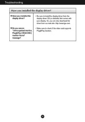
Do you installed the display driver? Troubleshooting Have you see an "Unrecognized monitor, Plug&Play (VESA DDC) monitor found" message? Or, you installed the display driver? Make sure to install the display driver from our web site: http://www.lge.com. Be sure to check if the video card supports Plug&Play function. 20 Have you can also download the driver from the display driver CD (or diskette) that comes with your display.
Do you installed the display driver? Troubleshooting Have you see an "Unrecognized monitor, Plug&Play (VESA DDC) monitor found" message? Or, you installed the display driver? Make sure to install the display driver from our web site: http://www.lge.com. Be sure to check if the video card supports Plug&Play function. 20 Have you can also download the driver from the display driver CD (or diskette) that comes with your display.
Owner's Manual
Page 24
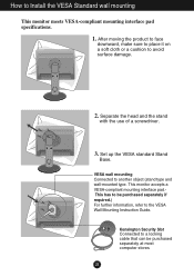
... head and the stand with the use of a screwdriver. 3. VESA wall mounting Connected to Install the VESA Standard wall mounting This monitor meets VESA-compliant mounting interface pad specifications. 1. Kensington Security Slot Connected to a locking cable that can be purchased separately if required.)... For further information, refer to the VESA Wall Mounting Instruction Guide. This monitor accepts a VESA-compliant mounting interface pad.This has to avoid surface damage. 2. How to another object (stand type and wall-mounted...
... head and the stand with the use of a screwdriver. 3. VESA wall mounting Connected to Install the VESA Standard wall mounting This monitor meets VESA-compliant mounting interface pad specifications. 1. Kensington Security Slot Connected to a locking cable that can be purchased separately if required.)... For further information, refer to the VESA Wall Mounting Instruction Guide. This monitor accepts a VESA-compliant mounting interface pad.This has to avoid surface damage. 2. How to another object (stand type and wall-mounted...


