
User Guide
Page 2
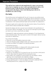
... this display. Contact your service technician for more than a short period of power supply you leave the room for replacement. On Safety Use only the power cord supplied with your dealer. Call your dealer if the display is easily accessible after installation. There are frayed power cords and broken plugs. Do not add accessories that the socket-outlet is not operating properly. Use only a stand recommended...
... this display. Contact your service technician for more than a short period of power supply you leave the room for replacement. On Safety Use only the power cord supplied with your dealer. Call your dealer if the display is easily accessible after installation. There are frayed power cords and broken plugs. Do not add accessories that the socket-outlet is not operating properly. Use only a stand recommended...

User Guide
Page 3
... mode except the recommended resolution, some scaled or processed images may cause some afterimages. Do not press the LCD screen with ventilation openings in enclosure unless proper ventilation is subject to obtain the best image quality for a long time as near a bathtub, washbowl, kitchen sink, laundry tub, in a wet basement, or near a swimming pool. On Cleaning Unplug the display before cleaning...
... mode except the recommended resolution, some scaled or processed images may cause some afterimages. Do not press the LCD screen with ventilation openings in enclosure unless proper ventilation is subject to obtain the best image quality for a long time as near a bathtub, washbowl, kitchen sink, laundry tub, in a wet basement, or near a swimming pool. On Cleaning Unplug the display before cleaning...
User Guide
Page 4
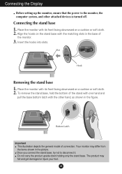
... the figure. Connecting the stand base 1. Place the monitor with the matching slots in the picture. To remove the stand base, hold the bottom of the stand with one hand and pull the base bottom latch with its front facing downward on a cushion or soft cloth. 2. A3 Connecting the Display Before setting up the monitor, ensure that the power to disconnect it. Slot Hook Removing the stand base 1. Bottom...
... the figure. Connecting the stand base 1. Place the monitor with the matching slots in the picture. To remove the stand base, hold the bottom of the stand with one hand and pull the base bottom latch with its front facing downward on a cushion or soft cloth. 2. A3 Connecting the Display Before setting up the monitor, ensure that the power to disconnect it. Slot Hook Removing the stand base 1. Bottom...
User Guide
Page 5
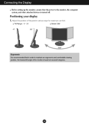
A4 Positioning your display 1. Connecting the Display Before setting up the monitor, ensure that the power to the monitor, the computer system, and other attached devices is recommended that in order to maintain an ergonomic and comfortable viewing position, the forward tilt angle of the panel in various ways for maximum comfort. Tilt Range : -5˚~20˚ Swivel :350˚ Ergonomic It is turned off. Adjust the position of the monitor should not exceed 5 degrees.
A4 Positioning your display 1. Connecting the Display Before setting up the monitor, ensure that the power to the monitor, the computer system, and other attached devices is recommended that in order to maintain an ergonomic and comfortable viewing position, the forward tilt angle of the panel in various ways for maximum comfort. Tilt Range : -5˚~20˚ Swivel :350˚ Ergonomic It is turned off. Adjust the position of the monitor should not exceed 5 degrees.
User Guide
Page 6
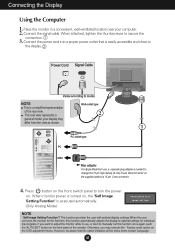
...) D-sub VGA connector on . Press button on the front switch panel to turn the power on the supplied cable to the display. NOTE Wall-outlet type This is easily accessible and close to a 15 pin 2 row connector. 4. This rear view represents a 2 general model; This function provides the user with optimal display settings.When the user connects the monitor for individual input signals. When monitor power is turned on, the 'Self Image Setting Function' is needed to adjust the monitor while in...
...) D-sub VGA connector on . Press button on the front switch panel to turn the power on the supplied cable to the display. NOTE Wall-outlet type This is easily accessible and close to a 15 pin 2 row connector. 4. This rear view represents a 2 general model; This function provides the user with optimal display settings.When the user connects the monitor for individual input signals. When monitor power is turned on, the 'Self Image Setting Function' is needed to adjust the monitor while in...
User Guide
Page 7
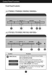
You can unlock the OSD controls at any time by pushing the MENU button for 5 seconds. A6 The message "OSD LOCKED" should appear. Press and hold the MENU button for 5 seconds. OSD LOCKED/UNLOCKED This function allows you to enter or exit the On Screen Display. The message "OSD UNLOCKED" should appear. Control Panel Functions Front Panel Controls Control MENU Button Function Use this button to lock the current control settings, so that they cannot be inadvertently changed.
You can unlock the OSD controls at any time by pushing the MENU button for 5 seconds. A6 The message "OSD LOCKED" should appear. Press and hold the MENU button for 5 seconds. OSD LOCKED/UNLOCKED This function allows you to enter or exit the On Screen Display. The message "OSD UNLOCKED" should appear. Control Panel Functions Front Panel Controls Control MENU Button Function Use this button to lock the current control settings, so that they cannot be inadvertently changed.
User Guide
Page 8
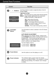
... etc.) • MOVIE : For animation images in videos or movies • PHOTO : For pictures or drawings • NORMAL : This is 17 inch monitor : 1280x1024 19 inch monitor : 1280x1024 Power Button Use this indicator color changes to the ideal settings for the current screen resolution size (display mode). AUTO IMAGE ADJUSTMENT When adjusting your display image to amber. Power Indicator This Indicator lights up green when the display operates normally(On Mode). Control Panel Functions Control Function - + Buttons Use these buttons to turn the display on or off.
... etc.) • MOVIE : For animation images in videos or movies • PHOTO : For pictures or drawings • NORMAL : This is 17 inch monitor : 1280x1024 19 inch monitor : 1280x1024 Power Button Use this indicator color changes to the ideal settings for the current screen resolution size (display mode). AUTO IMAGE ADJUSTMENT When adjusting your display image to amber. Power Indicator This Indicator lights up green when the display operates normally(On Mode). Control Panel Functions Control Function - + Buttons Use these buttons to turn the display on or off.
User Guide
Page 10
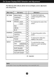
A9 Main menu Sub menu PICTURE BRIGHTNESS CONTRAST COLOR GAMMA PRESET 6500K 9300K RED GREEN BLUE POSITION HORIZONTAL VERTICAL TRACKING CLOCK PHASE SETUP LANGUAGE OSD HORIZONTAL POSITION VERTICAL WHITE BALANCE POWER INDICATOR FACTORY RESET Reference To adjust the brightness, contrast and gamma of the screen To customize the color of the screen To adjust the position of the screen To improve the clarity and stability of the screen To customize the screen status for a user's operating environment : Adjustable NOTE The order of icons may differ depending...
A9 Main menu Sub menu PICTURE BRIGHTNESS CONTRAST COLOR GAMMA PRESET 6500K 9300K RED GREEN BLUE POSITION HORIZONTAL VERTICAL TRACKING CLOCK PHASE SETUP LANGUAGE OSD HORIZONTAL POSITION VERTICAL WHITE BALANCE POWER INDICATOR FACTORY RESET Reference To adjust the brightness, contrast and gamma of the screen To customize the color of the screen To adjust the position of the screen To improve the clarity and stability of the screen To customize the screen status for a user's operating environment : Adjustable NOTE The order of icons may differ depending...
User Guide
Page 11
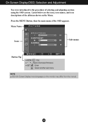
On Screen Display(OSD) Selection and Adjustment You were introduced to the procedure of the OSD appears. A10 Menu Name PICTURE Icons Sub-menus Button Tip MENU : Exit - + : Adjust (Decrease/Increase) SET : Enter : Select another sub-menu NOTE OSD (On Screen Display) menu languages on the Menu. Press the MENU Button, then the main menu of selecting and adjusting an item using the OSD system. Listed below are the icons, icon names, and icon descriptions of the all items shown on the monitor may differ from the manual.
On Screen Display(OSD) Selection and Adjustment You were introduced to the procedure of the OSD appears. A10 Menu Name PICTURE Icons Sub-menus Button Tip MENU : Exit - + : Adjust (Decrease/Increase) SET : Enter : Select another sub-menu NOTE OSD (On Screen Display) menu languages on the Menu. Press the MENU Button, then the main menu of selecting and adjusting an item using the OSD system. Listed below are the icons, icon names, and icon descriptions of the all items shown on the monitor may differ from the manual.
User Guide
Page 13
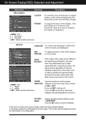
.... FACTORY RESET Restore all factory default settings except "LANGUAGE." If necessary, perform the white balance function again. A12 MENU : Exit +- : Decrease : Increase SET : Select another sub-menu Use this function, the signal level is an analog signal. Press the button to provide the optimal image. This function will be turned on the screen background.The horizontal screen size will also change. On Screen Display(OSD) Selection and Adjustment Main menu TRACKING TRACKING Sub menu Description CLOCK To minimize any vertical...
.... FACTORY RESET Restore all factory default settings except "LANGUAGE." If necessary, perform the white balance function again. A12 MENU : Exit +- : Decrease : Increase SET : Select another sub-menu Use this function, the signal level is an analog signal. Press the button to provide the optimal image. This function will be turned on the screen background.The horizontal screen size will also change. On Screen Display(OSD) Selection and Adjustment Main menu TRACKING TRACKING Sub menu Description CLOCK To minimize any vertical...
User Guide
Page 14
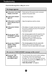
... the signal cable between your PC and your display again. Press the Power button. Adjust the brightness and the contrast. Do you push MENU button? Try to the power outlet. No image appears Is the power cord of this manual and configure your display is out of horizontal or vertical frequency range of the display. Is the power indicator amber? This message appears when the signal from the PC (video card) is not connected. Check the signal cable and...
... the signal cable between your PC and your display again. Press the Power button. Adjust the brightness and the contrast. Do you push MENU button? Try to the power outlet. No image appears Is the power cord of this manual and configure your display is out of horizontal or vertical frequency range of the display. Is the power indicator amber? This message appears when the signal from the PC (video card) is not connected. Check the signal cable and...
User Guide
Page 15
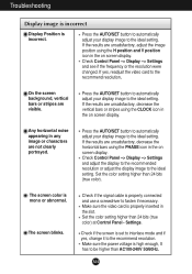
... recommend resolution. Set the color setting higher than 24 bits (true color) at Control Panel - Check Control Panel --> Display --> Settings and see if the frequency or the resolution were changed. Make sure the power voltage is set to interlace mode and if yes, change it to the recommend resolution. Make sure the video card is mono or abnormal. The screen color is properly inserted in the on screen display. Check if the signal cable is incorrect. Troubleshooting Display image is incorrect Display Position is properly connected and use...
... recommend resolution. Set the color setting higher than 24 bits (true color) at Control Panel - Check Control Panel --> Display --> Settings and see if the frequency or the resolution were changed. Make sure the power voltage is set to interlace mode and if yes, change it to the recommend resolution. Make sure the video card is mono or abnormal. The screen color is properly inserted in the on screen display. Check if the signal cable is incorrect. Troubleshooting Display image is incorrect Display Position is properly connected and use...
User Guide
Page 16
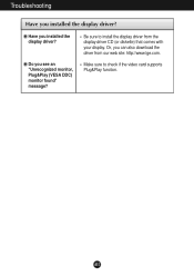
Or, you installed the display driver? Do you installed the display driver? Troubleshooting Have you see an "Unrecognized monitor, Plug&Play (VESA DDC) monitor found" message? Make sure to install the display driver from our web site: http://www.lge.com. A15 Be sure to check if the video card supports Plug&Play function. Have you can also download the driver from the display driver CD (or diskette) that comes with your display.
Or, you installed the display driver? Do you installed the display driver? Troubleshooting Have you see an "Unrecognized monitor, Plug&Play (VESA DDC) monitor found" message? Make sure to install the display driver from our web site: http://www.lge.com. A15 Be sure to check if the video card supports Plug&Play function. Have you can also download the driver from the display driver CD (or diskette) that comes with your display.
User Guide
Page 17
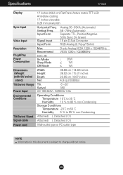
... 5 % to 95 % non-Condensing Attached( ), Detached ( O ) Attached( ), Detached ( O ) Wall-outlet type or PC-outlet type NOTE Information in this document is subject to change without notice. Vertical Freq. Specifications 17 inch Display Sync Input Video Input Resolution Plug&Play Power Consumption Dimensions &Weight (with tilt/ swivel stand) Tilt/Swivel Range Power Input Environmental Conditions Tilt/Swivel Stand Signal cable Power cord 17 inches (43.2 cm) Flat Panel Active matrix-TFT LCD Anti-Glare coating 17 inches viewable 0.26 mm pixel pitch Horizontal Freq.
... 5 % to 95 % non-Condensing Attached( ), Detached ( O ) Attached( ), Detached ( O ) Wall-outlet type or PC-outlet type NOTE Information in this document is subject to change without notice. Vertical Freq. Specifications 17 inch Display Sync Input Video Input Resolution Plug&Play Power Consumption Dimensions &Weight (with tilt/ swivel stand) Tilt/Swivel Range Power Input Environmental Conditions Tilt/Swivel Stand Signal cable Power cord 17 inches (43.2 cm) Flat Panel Active matrix-TFT LCD Anti-Glare coating 17 inches viewable 0.26 mm pixel pitch Horizontal Freq.
User Guide
Page 18
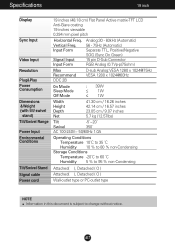
... 5 % to 95 % non-Condensing Attached( ), Detached ( O ) Attached( ), Detached ( O ) Wall-outlet type or PC-outlet type NOTE Information in this document is subject to change without notice. Specifications 19 inch Display Sync Input Video Input Resolution Plug&Play Power Consumption Dimensions &Weight (with tilt/ swivel stand) Tilt/Swivel Range Power Input Environmental Conditions Tilt/Swivel Stand Signal cable Power cord 19 inches (48.18 cm) Flat Panel Active matrix-TFT LCD Anti-Glare coating 19 inches viewable 0.294 mm pixel pitch Horizontal Freq.
... 5 % to 95 % non-Condensing Attached( ), Detached ( O ) Attached( ), Detached ( O ) Wall-outlet type or PC-outlet type NOTE Information in this document is subject to change without notice. Specifications 19 inch Display Sync Input Video Input Resolution Plug&Play Power Consumption Dimensions &Weight (with tilt/ swivel stand) Tilt/Swivel Range Power Input Environmental Conditions Tilt/Swivel Stand Signal cable Power cord 19 inches (48.18 cm) Flat Panel Active matrix-TFT LCD Anti-Glare coating 19 inches viewable 0.294 mm pixel pitch Horizontal Freq.
Service Manual
Page 1
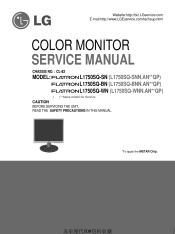
Website:http://biz.LGservice.com E-mail:http://www.LGEservice.com/techsup.html COLOR MONITOR SERVICE MANUAL CHASSIS NO. : CL-82 MODEL: L1750SQ-SN (L1750SQ-SNN.AN**QP) L1750SQ-BN (L1750SQ-BNN.AN**QP) L1750SQ-WN (L1750SQ-WNN.AN**QP) ( ) **Same model for Service CAUTION BEFORE SERVICING THE UNIT, READ THE SAFETY PRECAUTIONS IN THIS MANUAL. *To apply the MSTAR Chip. 龙泉现代YDW资料收藏
Website:http://biz.LGservice.com E-mail:http://www.LGEservice.com/techsup.html COLOR MONITOR SERVICE MANUAL CHASSIS NO. : CL-82 MODEL: L1750SQ-SN (L1750SQ-SNN.AN**QP) L1750SQ-BN (L1750SQ-BNN.AN**QP) L1750SQ-WN (L1750SQ-WNN.AN**QP) ( ) **Same model for Service CAUTION BEFORE SERVICING THE UNIT, READ THE SAFETY PRECAUTIONS IN THIS MANUAL. *To apply the MSTAR Chip. 龙泉现代YDW资料收藏
Service Manual
Page 3
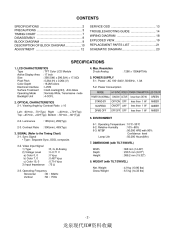
OPTICAL CHARACTERISTICS 2-1. Resolution D-sub Analog : 1280 x 1024@75Hz 5. CONTENTS SPECIFICATIONS ...2 PRECAUTIONS ...3 TIMING CHART ...7 DISASSEMBLY ...8 BLOCK DIAGRAM ...9 DESCRIPTION OF BLOCK DIAGRAM...10 ADJUSTMENT ...12 SERVICE OSD ...13 TROUBLESHOOTING GUIDE ...14 WIRING DIAGRAM ...18 EXPLODED VIEW...19 REPLACEMENT PARTS LIST ...21 SCHEMATIC DIAGRAM ...23 SPECIFICATIONS 1. Luminance 2-3. Power : AC 100~240V, 50/60Hz , 1.0A 5-2. ENVIRONMENT 3. Weight Gross Weight : 4.9 kg (10.80 lbs) : 6.5 kg (14.33 lbs) 3-3. DIMENSIONS (with 90% Confidence level Lamp Life...
OPTICAL CHARACTERISTICS 2-1. Resolution D-sub Analog : 1280 x 1024@75Hz 5. CONTENTS SPECIFICATIONS ...2 PRECAUTIONS ...3 TIMING CHART ...7 DISASSEMBLY ...8 BLOCK DIAGRAM ...9 DESCRIPTION OF BLOCK DIAGRAM...10 ADJUSTMENT ...12 SERVICE OSD ...13 TROUBLESHOOTING GUIDE ...14 WIRING DIAGRAM ...18 EXPLODED VIEW...19 REPLACEMENT PARTS LIST ...21 SCHEMATIC DIAGRAM ...23 SPECIFICATIONS 1. Luminance 2-3. Power : AC 100~240V, 50/60Hz , 1.0A 5-2. ENVIRONMENT 3. Weight Gross Weight : 4.9 kg (10.80 lbs) : 6.5 kg (14.33 lbs) 3-3. DIMENSIONS (with 90% Confidence level Lamp Life...
Service Manual
Page 5
... and semiconductor "chip" components. Do not remove a replacement ES device from the leads of a replacement ES device, touch the protective material to the chassis or circuit assembly into which receivers covered by this service manual might be damaged easily by static electricity. a. Connecting a test substitute in not required. 6. Unless specified otherwise in this service manual, clean electrical contacts only by applying the...
... and semiconductor "chip" components. Do not remove a replacement ES device from the leads of a replacement ES device, touch the protective material to the chassis or circuit assembly into which receivers covered by this service manual might be damaged easily by static electricity. a. Connecting a test substitute in not required. 6. Unless specified otherwise in this service manual, clean electrical contacts only by applying the...
Service Manual
Page 13
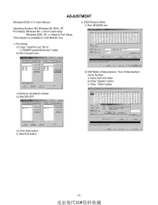
... Manufacture, Year of Manufacture, Serial Number a) Input User Info Data b) Click "Update" button c) Click " Write" button c) Remove all default number d) Add 300-3FF e) Click Start button. Port Setup a) Copy "UserPort.sys" file to Port Setup. f) Click Exit button. - 12 - 龙泉现代YDW资料收藏 ADJUSTMENT Windows EDID V1.0 User Manual Operating System: MS Windows 98, 2000, XP Port Setup: Windows 98 => Don't need setup Windows 2000, XP => Need to "c:\WINNT\system32\drivers" folder b) Run Userport.exe...
... Manufacture, Year of Manufacture, Serial Number a) Input User Info Data b) Click "Update" button c) Click " Write" button c) Remove all default number d) Add 300-3FF e) Click Start button. Port Setup a) Copy "UserPort.sys" file to Port Setup. f) Click Exit button. - 12 - 龙泉现代YDW资料收藏 ADJUSTMENT Windows EDID V1.0 User Manual Operating System: MS Windows 98, 2000, XP Port Setup: Windows 98 => Don't need setup Windows 2000, XP => Need to "c:\WINNT\system32\drivers" folder b) Run Userport.exe...
Service Manual
Page 14
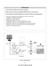
... manually. Cable Connection - 13 - 龙泉现代YDW资料收藏 d) AGING : Select Aging mode(on/off the power switch at the front side of the display. 2) Wait for about 5 seconds and press MENU, POWER switch with 1 second interval. 3) The SVC OSD menu contains additional menus that the User OSD menu as described below. f) R/G/B-6500K : Allows you to set the R/G/B-9300K value manually. A 9 6 1 Video Signal Generator IBM Compatible...
... manually. Cable Connection - 13 - 龙泉现代YDW资料收藏 d) AGING : Select Aging mode(on/off the power switch at the front side of the display. 2) Wait for about 5 seconds and press MENU, POWER switch with 1 second interval. 3) The SVC OSD menu contains additional menus that the User OSD menu as described below. f) R/G/B-6500K : Allows you to set the R/G/B-9300K value manually. A 9 6 1 Video Signal Generator IBM Compatible...


