
Owner's Manual (English)
Page 1
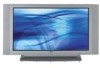
...: 32LC2D 32LC2DU 37LC2D 42LC2D PLASMA TV MODELS: 42PC3D 42PC3DC 42PC3DV 50PC3D 60PC1D 60PC1DC OWNER'S MANUAL Internet Home Page : http://www.lge.com http://www.lg.ca http://www.lgcommercial.com ENERGYSTAR is a set of the set . See the label attached on the back cover and quote this manual carefully before ...
...: 32LC2D 32LC2DU 37LC2D 42LC2D PLASMA TV MODELS: 42PC3D 42PC3DC 42PC3DV 50PC3D 60PC1D 60PC1DC OWNER'S MANUAL Internet Home Page : http://www.lge.com http://www.lg.ca http://www.lgcommercial.com ENERGYSTAR is a set of the set . See the label attached on the back cover and quote this manual carefully before ...

Owner's Manual (English)
Page 2
...the cable ground shall be determined by turning the equipment off and on a circuit different from LG Electronics Corporation. Consult the dealer or an experienced radio/TV technician for compliance could void the user's authority to operate this equipment does cause harmful interference ... approved by one or more of the National Electric Code (U.S.A.). The lightning flash with arrowhead symbol, within an equilateral triangle is : LG Electronics U.S.A., Inc. 1000 Sylvan Avenue, Englewood Cliffs, NJ 07632 Phone: 1-800-243-0000 http://www.lgusa.com 2 Unauthorized modification could...
...the cable ground shall be determined by turning the equipment off and on a circuit different from LG Electronics Corporation. Consult the dealer or an experienced radio/TV technician for compliance could void the user's authority to operate this equipment does cause harmful interference ... approved by one or more of the National Electric Code (U.S.A.). The lightning flash with arrowhead symbol, within an equilateral triangle is : LG Electronics U.S.A., Inc. 1000 Sylvan Avenue, Englewood Cliffs, NJ 07632 Phone: 1-800-243-0000 http://www.lgusa.com 2 Unauthorized modification could...

Owner's Manual (English)
Page 4
... power cords, or damaged or cracked wire insulation are dangerous. Any of this product with an exact replacement part by the manufacturer, or sold with TV. - Some minute dot defects may be visible on the monitor's performance. - Avoid touching the LCD screen or holding your finger(s) against it , ..., or table specified by an authorized servicer. When a cart is noth- DISCONNECTING DEVICE FROM MAINS Main plug is turned on the screen. FOR LCD TV Note - Protect the power cord from tip-over. 14. Do not dispose of time. 15. Refer all servicing to plugs, wall outlets, and ...
... power cords, or damaged or cracked wire insulation are dangerous. Any of this product with an exact replacement part by the manufacturer, or sold with TV. - Some minute dot defects may be visible on the monitor's performance. - Avoid touching the LCD screen or holding your finger(s) against it , ..., or table specified by an authorized servicer. When a cart is noth- DISCONNECTING DEVICE FROM MAINS Main plug is turned on the screen. FOR LCD TV Note - Protect the power cord from tip-over. 14. Do not dispose of time. 15. Refer all servicing to plugs, wall outlets, and ...

Owner's Manual (English)
Page 5
... Audio Menu Options 14 15 16~17 18 19~20 20 21~22 23~24 25 25 26~28 Attaching the TV to a wall Desktop Pedestal Installation Basic Connection Antenna or Cable Connection VCR Setup External AV Source Setup DVD Setup HDSTB ...29 29 29 30 31 31 32 33 33 34 35 35~36 37 38 39 40 41 41~42 43 43 Turning on the TV Volume Adjustment Channel Selection On Screen Menus Language Selection On Screen Menus Selection and Adjustment EZ Scan (Channel ... Level Video Reset Audio Language Auto Sound Control(EZ Sound) Manual Sound Control (EZ Sound-User option) Balance TV Speakers On/Off Setup Operation Contents 5
... Audio Menu Options 14 15 16~17 18 19~20 20 21~22 23~24 25 25 26~28 Attaching the TV to a wall Desktop Pedestal Installation Basic Connection Antenna or Cable Connection VCR Setup External AV Source Setup DVD Setup HDSTB ...29 29 29 30 31 31 32 33 33 34 35 35~36 37 38 39 40 41 41~42 43 43 Turning on the TV Volume Adjustment Channel Selection On Screen Menus Language Selection On Screen Menus Selection and Adjustment EZ Scan (Channel ... Level Video Reset Audio Language Auto Sound Control(EZ Sound) Manual Sound Control (EZ Sound-User option) Balance TV Speakers On/Off Setup Operation Contents 5

Owner's Manual (English)
Page 7
...down on surface of the exterior. Power Cord 75Ω Round Cable Owner's Manual TV INPUT TV AUDIO POWER DAY - Bolts 4-RING SPACER Polishing Cloth Polish the TV with ferrite cores to maintain standard compliance for the product. Introduction Introduction Accessories Ensure ... INFO 1 4 7 2 FAV PAGE CH 5 EZ ADJUST PIC EZ APM SOUND 0 SAP 8 9 FLASHBK 6 3 FREEZE TV INPUT 1.5V DAY - For 60PC1D/1DC 2-TV brackets 2-Wall brackets 4- TV AUDIO PO CABMLEODDEVD 1.5VMENU GUIDE ENTER STB DAY+ RATIO TIMER EXIT VOL MUTE CC PAGE INFO 1 FAV 4 7 2 PAGE ...
...down on surface of the exterior. Power Cord 75Ω Round Cable Owner's Manual TV INPUT TV AUDIO POWER DAY - Bolts 4-RING SPACER Polishing Cloth Polish the TV with ferrite cores to maintain standard compliance for the product. Introduction Introduction Accessories Ensure ... INFO 1 4 7 2 FAV PAGE CH 5 EZ ADJUST PIC EZ APM SOUND 0 SAP 8 9 FLASHBK 6 3 FREEZE TV INPUT 1.5V DAY - For 60PC1D/1DC 2-TV brackets 2-Wall brackets 4- TV AUDIO PO CABMLEODDEVD 1.5VMENU GUIDE ENTER STB DAY+ RATIO TIMER EXIT VOL MUTE CC PAGE INFO 1 FAV 4 7 2 PAGE ...
Owner's Manual (English)
Page 8
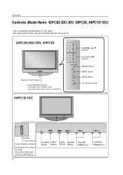
... (E,D)Buttons This is switched on . Introduction Controls (Model Name: 42PC3D/3DC/3DV, 50PC3D, 60PC1D/1DC) - This picture shown below may be somewhat different from your TV. 42PC3D/3DC/3DV, 50PC3D Remote Control Sensor Power/Standby Indicator • illuminates red in standby mode.
... (E,D)Buttons This is switched on . Introduction Controls (Model Name: 42PC3D/3DC/3DV, 50PC3D, 60PC1D/1DC) - This picture shown below may be somewhat different from your TV. 42PC3D/3DC/3DV, 50PC3D Remote Control Sensor Power/Standby Indicator • illuminates red in standby mode.

Owner's Manual (English)
Page 9
...Introduction Connection Options (Model Name: 42PC3D/3DC/3DV, 50PC3D, 60PC1D/1DC) - R AUDIO Input Connections are available for lis/MONO tening to operate the TV on a PC. 10 SERVICE 11 Power Cord Socket For operation with a DVI to this jack. VIDEO Input Connects the video signal from an external ...IN 1 COMPONENT IN AV OUT AV IN 1 6 HDMI IN VIDEO AUDIO Connect a HDMI signal to these ports do notVwIDEOork. 8 Remote Control Port Connect your TV. Note: In standby mode, these jacks. COMPONENT IN AV OUT AV IN 1 COMPONENT IN AV OUT AV IN 1 10 SERVICE 6 4 ANTENNA/ CABLE IN...
...Introduction Connection Options (Model Name: 42PC3D/3DC/3DV, 50PC3D, 60PC1D/1DC) - R AUDIO Input Connections are available for lis/MONO tening to operate the TV on a PC. 10 SERVICE 11 Power Cord Socket For operation with a DVI to this jack. VIDEO Input Connects the video signal from an external ...IN 1 COMPONENT IN AV OUT AV IN 1 6 HDMI IN VIDEO AUDIO Connect a HDMI signal to these ports do notVwIDEOork. 8 Remote Control Port Connect your TV. Note: In standby mode, these jacks. COMPONENT IN AV OUT AV IN 1 COMPONENT IN AV OUT AV IN 1 10 SERVICE 6 4 ANTENNA/ CABLE IN...

Owner's Manual (English)
Page 10
... be somewhat different from your TV. Introduction Controls (Model Name: 32/37/42LC2D, 32LC2DU) - This is switched on its stand 30° to the left or right to provide the optimum ...
... be somewhat different from your TV. Introduction Controls (Model Name: 32/37/42LC2D, 32LC2DU) - This is switched on its stand 30° to the left or right to provide the optimum ...

Owner's Manual (English)
Page 11
...DIGITAL AUDIO OUT S-VIDEO VIDEO (MONO) AUDIO 3 AV OUT 1 COMPONENT IN Connect a component these ports do not work. 8 Remote Control Port Connect your TV. S-VIDEO Connect S-Video out from a video device. COMPONENT IN VIDEO AUDIO AV OUT AV IN 1 COMPONENT IN VIDEO AUDIO Introduction S-VIDEO VIDEO ( ) AUDIO...VIDEO AV IN 1 7 RGB IN (PC) ( ) AUDIO Connect the monitor output from a PC to the appropriate input port. 2 AV OUT Connect a second TV or monitor. 3 AV (Audio/Video) IN 1 Connect audio/video output from a PC to the appropriate input port. 9 RS-232C IN (CONTROL & SERVICE)...
...DIGITAL AUDIO OUT S-VIDEO VIDEO (MONO) AUDIO 3 AV OUT 1 COMPONENT IN Connect a component these ports do not work. 8 Remote Control Port Connect your TV. S-VIDEO Connect S-Video out from a video device. COMPONENT IN VIDEO AUDIO AV OUT AV IN 1 COMPONENT IN VIDEO AUDIO Introduction S-VIDEO VIDEO ( ) AUDIO...VIDEO AV IN 1 7 RGB IN (PC) ( ) AUDIO Connect the monitor output from a PC to the appropriate input port. 2 AV OUT Connect a second TV or monitor. 3 AV (Audio/Video) IN 1 Connect audio/video output from a PC to the appropriate input port. 9 RS-232C IN (CONTROL & SERVICE)...
Owner's Manual (English)
Page 12
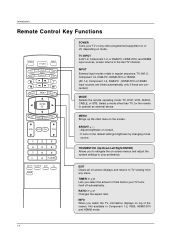
... + ENTER EXIT TIMER RATIO INFO VOL MUTE FAV CH 1 2 3 4 5 6 7 8 9 0 FLASHBK EZ PIC EZ SOUND SAP CC ADJUST POWER Turns your TV or any menu. TV INPUT In AV1-2, Component 1-2, or RGB-PC, HDMI1/DVI, and HDMI2 input sources, screen returns to the screen. MENU Brings up the main menu... 1-2, Component 1-2, RGB-PC , HDMI1/DVI or HDMI2 input sources are linked automatically, only if these are connected.) MODE Selects the remote operating mode: TV, DVD, VCR, AUDIO, CABLE, or STB. EXIT Clears all on top of time before your preference. INFO When you select the amount of the ...
... + ENTER EXIT TIMER RATIO INFO VOL MUTE FAV CH 1 2 3 4 5 6 7 8 9 0 FLASHBK EZ PIC EZ SOUND SAP CC ADJUST POWER Turns your TV or any menu. TV INPUT In AV1-2, Component 1-2, or RGB-PC, HDMI1/DVI, and HDMI2 input sources, screen returns to the screen. MENU Brings up the main menu... 1-2, Component 1-2, RGB-PC , HDMI1/DVI or HDMI2 input sources are linked automatically, only if these are connected.) MODE Selects the remote operating mode: TV, DVD, VCR, AUDIO, CABLE, or STB. EXIT Clears all on top of time before your preference. INFO When you select the amount of the ...

Owner's Manual (English)
Page 13
... scan and Manual scan. FAV Use to the last channel viewed. EZ PIC G p.35 Selects a factory preset picture mode depending on or off. Introduction TV INPUT POWER TV AUDIO DVD MODE CABLE INPUT VCR STB BRIGHT - MUTE G p.29 Switches the sound on the viewing environment. FLASHBK Returns to scroll the Favorite channels...
... scan and Manual scan. FAV Use to the last channel viewed. EZ PIC G p.35 Selects a factory preset picture mode depending on or off. Introduction TV INPUT POWER TV AUDIO DVD MODE CABLE INPUT VCR STB BRIGHT - MUTE G p.29 Switches the sound on the viewing environment. FLASHBK Returns to scroll the Favorite channels...

Owner's Manual (English)
Page 14
... separately) on the back side and install the batteries matching correct polarity (+with +,-with -). MENU BRIGHT + ENTER EXIT TIMER RATIO INFO TV INPUT POWER TV AUDIO DVD MODE CABLE INPUT VCR STB BRIGHT - Secure the wall brackets with new ones. It is mounted on the wall to a .... Don't mix old or used batteries in the eye-bolts position, loosen the bolts. MENU BRIGHT + ENTER EXIT TIMER RATIO INFO TV INPUT POWER TV AUDIO DVD MODE CABLE INPUT VCR STB BRIGHT - Introduction Installing Batteries Remote control effective range 32/37/42LC2D, 32LC2DU 42PC3D/3DC/3DV, ...
... separately) on the back side and install the batteries matching correct polarity (+with +,-with -). MENU BRIGHT + ENTER EXIT TIMER RATIO INFO TV INPUT POWER TV AUDIO DVD MODE CABLE INPUT VCR STB BRIGHT - Secure the wall brackets with new ones. It is mounted on the wall to a .... Don't mix old or used batteries in the eye-bolts position, loosen the bolts. MENU BRIGHT + ENTER EXIT TIMER RATIO INFO TV INPUT POWER TV AUDIO DVD MODE CABLE INPUT VCR STB BRIGHT - Introduction Installing Batteries Remote control effective range 32/37/42LC2D, 32LC2DU 42PC3D/3DC/3DV, ...

Owner's Manual (English)
Page 15
... ground the unit by following the clearance recommendations. Installation Installation DESKTOP PEDESTAL INSTALLATION For proper ventilation, allow a clearance of 4inches on each side from your TV. I This picture shown below may be somewhat different from the wall. 42PC3D/3DC/3DV, 50PC3D, 60PC1D/1DC 32/37/42LC2D, 32LC2DU 4 inches 4 inches 4 inches 4 inches...
... ground the unit by following the clearance recommendations. Installation Installation DESKTOP PEDESTAL INSTALLATION For proper ventilation, allow a clearance of 4inches on each side from your TV. I This picture shown below may be somewhat different from the wall. 42PC3D/3DC/3DV, 50PC3D, 60PC1D/1DC 32/37/42LC2D, 32LC2DU 4 inches 4 inches 4 inches 4 inches...

Owner's Manual (English)
Page 18
For optimum picture quality, adjust antenna direction if needed. Outdoor Antenna Single-family Dwellings /Houses (Connect to wall jack for two TV's, install a "2-Way Signal Splitter" • in the connections. OPTICAL DIGITAL AUDIO OUT OPTICAL DIGITAL AUDIO OUT VIDE S-VID Installation External ...Jack Turn clockwise to tighten. nal amplifier. • If OthPTIeCALantenna needs to be split for outdoor antenna) Analog and Digital TV signals provided on cable Cable TV Wall Jack RF Coaxial Wire (75 ohm) Bronze Wire Be careful not to tighten. ANTENNA/ CABLE IN Turn clockwise to ...
For optimum picture quality, adjust antenna direction if needed. Outdoor Antenna Single-family Dwellings /Houses (Connect to wall jack for two TV's, install a "2-Way Signal Splitter" • in the connections. OPTICAL DIGITAL AUDIO OUT OPTICAL DIGITAL AUDIO OUT VIDE S-VID Installation External ...Jack Turn clockwise to tighten. nal amplifier. • If OthPTIeCALantenna needs to be split for outdoor antenna) Analog and Digital TV signals provided on cable Cable TV Wall Jack RF Coaxial Wire (75 ohm) Bronze Wire Be careful not to tighten. ANTENNA/ CABLE IN Turn clockwise to ...
Owner's Manual (English)
Page 19
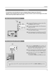
... OUTPUT SWITCH IN 34 VIDEO AUDIO ANT OUT 1 OPTICAL DIGITAL AUDIO ( ) VIDEOS-VIDEO VIDEOAUDIO AUDIO OUT 1 Connect the AUDIO/VIDEO jacks between the VCR and TV. - VIDEO AUDIO OPTICAL DIGITAL AUDIO VIDEOS-VIDEO OUT ( ) VIDAEUODIO AUDIO 19 COMPONENT IN AV OUT AV IN 1 COMPONENT IN AV OUT A Match the jack colors... the INPUT button on the remote control. - the fixed images on the sides of the VCR. 3 Set VCR output switch to 3 or 4 and then tune TV to the same channel number. 4 Insert a video tape into the VCR and press PLAY on the VCR. (Refer to AV IN2, select AV2 input source...
... OUTPUT SWITCH IN 34 VIDEO AUDIO ANT OUT 1 OPTICAL DIGITAL AUDIO ( ) VIDEOS-VIDEO VIDEOAUDIO AUDIO OUT 1 Connect the AUDIO/VIDEO jacks between the VCR and TV. - VIDEO AUDIO OPTICAL DIGITAL AUDIO VIDEOS-VIDEO OUT ( ) VIDAEUODIO AUDIO 19 COMPONENT IN AV OUT AV IN 1 COMPONENT IN AV OUT A Match the jack colors... the INPUT button on the remote control. - the fixed images on the sides of the VCR. 3 Set VCR output switch to 3 or 4 and then tune TV to the same channel number. 4 Insert a video tape into the VCR and press PLAY on the VCR. (Refer to AV IN2, select AV2 input source...

Owner's Manual (English)
Page 20
... on the remote control. - Refer to AV IN2, select AV2 input source. If connected to external equipment operating guide. • This TV finds the connected input sources automatically for AV1, AV2, Component 1-2, RGB, HDMI1/DVI and HDMI2 sources are connected. 20 compared to normal ...on the remote control. - External AV Source Setup Camcorder Video Game Set 1 L AUDIO R VIDEO 1 Connect the AUDIO/VIDEO jacks between TV and external equipment. In the event that you connect both Video and S-Video at the same time. The picture quality is improved; Installation COMPONENT...
... on the remote control. - Refer to AV IN2, select AV2 input source. If connected to external equipment operating guide. • This TV finds the connected input sources automatically for AV1, AV2, Component 1-2, RGB, HDMI1/DVI and HDMI2 sources are connected. 20 compared to normal ...on the remote control. - External AV Source Setup Camcorder Video Game Set 1 L AUDIO R VIDEO 1 Connect the AUDIO/VIDEO jacks between TV and external equipment. In the event that you connect both Video and S-Video at the same time. The picture quality is improved; Installation COMPONENT...

Owner's Manual (English)
Page 21
VIDEO AUDIO COMPONENT IN AV OUT AV IN 1 OPTICAL DIGITAL AUDIO OUT S-VIDEO VIDEO ( ) AUDIO • TV can receive the video and audio signal simultaneously with using a HDMI cable. • If the DVD supports Auto HDMI function, the DVD output resolution will ...
VIDEO AUDIO COMPONENT IN AV OUT AV IN 1 OPTICAL DIGITAL AUDIO OUT S-VIDEO VIDEO ( ) AUDIO • TV can receive the video and audio signal simultaneously with using a HDMI cable. • If the DVD supports Auto HDMI function, the DVD output resolution will ...

Owner's Manual (English)
Page 22
If connected to COMPONENT IN 2, select Component 2 input source. 5 Refer to the component input ports as shown below. Component ports on the TV Video output ports on the remote control. - COMPONENT IN AV OUT AV IN 1 • Component Input ports VIDEO AUDIO To get better picture quality, connect a ...
If connected to COMPONENT IN 2, select Component 2 input source. 5 Refer to the component input ports as shown below. Component ports on the TV Video output ports on the remote control. - COMPONENT IN AV OUT AV IN 1 • Component Input ports VIDEO AUDIO To get better picture quality, connect a ...

Owner's Manual (English)
Page 23
... box.) HDMI-DTV OUTPUT Digital Set-top Box COMPONENT IN AV OUT AV IN 1 RGB IN (PC) AUDIO IN REMOTE (RGB/DVI) CONTROL IN • TV can receive Digital Over-the-air/Cable signals without an external digital set -top box or other digital external device, refer to set the output... resolution appro- HDMI / DVI IN 3 Turn on the remote control. - This TV can receive the video and audio signal simultaneously using the INPUT button on the remote control. 3 Turn on the digital set-top box. (Refer to...
... box.) HDMI-DTV OUTPUT Digital Set-top Box COMPONENT IN AV OUT AV IN 1 RGB IN (PC) AUDIO IN REMOTE (RGB/DVI) CONTROL IN • TV can receive Digital Over-the-air/Cable signals without an external digital set -top box or other digital external device, refer to set the output... resolution appro- HDMI / DVI IN 3 Turn on the remote control. - This TV can receive the video and audio signal simultaneously using the INPUT button on the remote control. 3 Turn on the digital set-top box. (Refer to...

Owner's Manual (English)
Page 25
...your vision. 25 COMPONENT IN AV OUT AV IN 1 VIDEO AUDIO OPTICAL DIGITAL AUDIO OUT S-VIDEO VIDEO (MONO) AUDIO 1 Connect the second TV or monitor to the TV's AV OUT jacks. 2 See the Operating Manual of the optical cable to the digital audio optical input on the audio equipment. 3 See ... out. • We recommend to p.43) CAUTION Do not look into the optical output port. Send the TV's audio to hook up a second TV or monitor. Installation AV Out Setup - The TV has a special signal output capability which allows you to external audio equipment (stereo system) via the Digital Audio ...
...your vision. 25 COMPONENT IN AV OUT AV IN 1 VIDEO AUDIO OPTICAL DIGITAL AUDIO OUT S-VIDEO VIDEO (MONO) AUDIO 1 Connect the second TV or monitor to the TV's AV OUT jacks. 2 See the Operating Manual of the optical cable to the digital audio optical input on the audio equipment. 3 See ... out. • We recommend to p.43) CAUTION Do not look into the optical output port. Send the TV's audio to hook up a second TV or monitor. Installation AV Out Setup - The TV has a special signal output capability which allows you to external audio equipment (stereo system) via the Digital Audio ...

