
Owner's Manual (English)
Page 1
... model number and serial number of power-saving guidelines issued by the U.S. P/NO : 38289U0527F (0707-REV08) Printed in Korea S. A.,Inc. Environmental Protection Agency(EPA). LCD TV MODELS: 32LC2D 32LC2DU 37LC2D 42LC2D PLASMA TV MODELS: 42PC3D 42PC3DC 42PC3DV 50PC3D 60PC1D 60PC1DC OWNER'S MANUAL Internet Home Page : http://www.lge.com http://www...
... model number and serial number of power-saving guidelines issued by the U.S. P/NO : 38289U0527F (0707-REV08) Printed in Korea S. A.,Inc. Environmental Protection Agency(EPA). LCD TV MODELS: 32LC2D 32LC2DU 37LC2D 42LC2D PLASMA TV MODELS: 42PC3D 42PC3DC 42PC3DV 50PC3D 60PC1D 60PC1DC OWNER'S MANUAL Internet Home Page : http://www.lge.com http://www...

Owner's Manual (English)
Page 2
...changes or modifications not expressly approved by turning the equipment off and on a circuit different from LG Electronics Corporation. Connect the equipment into an outlet on , the user is : LG Electronics U.S.A., Inc. 1000 Sylvan Avenue, Englewood Cliffs, NJ 07632 Phone: 1-800-243-0000 ...in the literature accompanying the appliance. Increase the separation between the equipment and receiver. - Consult the dealer or an experienced radio/TV technician for a Class B digital device, pursuant to Part 15 of electric shock to operate this product in a residential installation...
...changes or modifications not expressly approved by turning the equipment off and on a circuit different from LG Electronics Corporation. Connect the equipment into an outlet on , the user is : LG Electronics U.S.A., Inc. 1000 Sylvan Avenue, Englewood Cliffs, NJ 07632 Phone: 1-800-243-0000 ...in the literature accompanying the appliance. Increase the separation between the equipment and receiver. - Consult the dealer or an experienced radio/TV technician for a Class B digital device, pursuant to Part 15 of electric shock to operate this product in a residential installation...

Owner's Manual (English)
Page 4
...to be placed upon . On Disposal a. b. Do not dispose of this product with an exact replacement part by the manufacturer, or sold with TV. - that appliance and has no adverse effect on . ing wrong with the apparatus. However, they be certain. Check the specification page of ... Use only with a cart, stand, tripod, bracket, or table specified by an authorized servicer. FOR LCD TV Note - Periodically examine the cord of time. Safety Instructions 12. If the TV feels cold to the touch, there may be a small "flicker" when when it for long periods of mercury...
...to be placed upon . On Disposal a. b. Do not dispose of this product with an exact replacement part by the manufacturer, or sold with TV. - that appliance and has no adverse effect on . ing wrong with the apparatus. However, they be certain. Check the specification page of ... Use only with a cart, stand, tripod, bracket, or table specified by an authorized servicer. FOR LCD TV Note - Periodically examine the cord of time. Safety Instructions 12. If the TV feels cold to the touch, there may be a small "flicker" when when it for long periods of mercury...

Owner's Manual (English)
Page 5
... Audio Menu Options 14 15 16~17 18 19~20 20 21~22 23~24 25 25 26~28 Attaching the TV to a wall Desktop Pedestal Installation Basic Connection Antenna or Cable Connection VCR Setup External AV Source Setup DVD Setup HDSTB ...29 29 29 30 31 31 32 33 33 34 35 35~36 37 38 39 40 41 41~42 43 43 Turning on the TV Volume Adjustment Channel Selection On Screen Menus Language Selection On Screen Menus Selection and Adjustment EZ Scan (Channel ... Level Video Reset Audio Language Auto Sound Control(EZ Sound) Manual Sound Control (EZ Sound-User option) Balance TV Speakers On/Off Setup Operation Contents 5
... Audio Menu Options 14 15 16~17 18 19~20 20 21~22 23~24 25 25 26~28 Attaching the TV to a wall Desktop Pedestal Installation Basic Connection Antenna or Cable Connection VCR Setup External AV Source Setup DVD Setup HDSTB ...29 29 29 30 31 31 32 33 33 34 35 35~36 37 38 39 40 41 41~42 43 43 Turning on the TV Volume Adjustment Channel Selection On Screen Menus Language Selection On Screen Menus Selection and Adjustment EZ Scan (Channel ... Level Video Reset Audio Language Auto Sound Control(EZ Sound) Manual Sound Control (EZ Sound-User option) Balance TV Speakers On/Off Setup Operation Contents 5

Owner's Manual (English)
Page 7
...use shielded signal interface cables(D-sub 15 pin cable) with the cloth. Power Cord 75Ω Round Cable Owner's Manual TV INPUT TV AUDIO POWER DAY - TV AUDIO PO CABMLEODDEVD 1.5VMENU GUIDE ENTER STB DAY+ RATIO TIMER EXIT VOL MUTE CC PAGE INFO 1 FAV 4 7 2... 1 4 7 2 FAV PAGE CH 5 EZ ADJUST PIC EZ APM SOUND 0 SAP 8 9 FLASHBK 6 3 FREEZE TV INPUT 1.5V DAY - For 60PC1D/1DC 2-TV brackets 2-Wall brackets 4- Introduction Introduction Accessories Ensure that excessive power may cause scratch or discoloration. Stand Installation for the product ...
...use shielded signal interface cables(D-sub 15 pin cable) with the cloth. Power Cord 75Ω Round Cable Owner's Manual TV INPUT TV AUDIO POWER DAY - TV AUDIO PO CABMLEODDEVD 1.5VMENU GUIDE ENTER STB DAY+ RATIO TIMER EXIT VOL MUTE CC PAGE INFO 1 FAV 4 7 2... 1 4 7 2 FAV PAGE CH 5 EZ ADJUST PIC EZ APM SOUND 0 SAP 8 9 FLASHBK 6 3 FREEZE TV INPUT 1.5V DAY - For 60PC1D/1DC 2-TV brackets 2-Wall brackets 4- Introduction Introduction Accessories Ensure that excessive power may cause scratch or discoloration. Stand Installation for the product ...
Owner's Manual (English)
Page 8
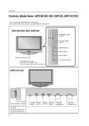
... on . 8 ENTER ENTER POWER INPUT Button Button MENU ENTER Button Button VOLUME (F,G)Buttons CHANNEL (E,D)Buttons This picture shown below may be somewhat different from your TV. 42PC3D/3DC/3DV, 50PC3D Remote Control Sensor Power/Standby Indicator • illuminates red in standby mode. Introduction Controls (Model Name: 42PC3D/3DC/3DV, 50PC3D, 60PC1D...
... on . 8 ENTER ENTER POWER INPUT Button Button MENU ENTER Button Button VOLUME (F,G)Buttons CHANNEL (E,D)Buttons This picture shown below may be somewhat different from your TV. 42PC3D/3DC/3DV, 50PC3D Remote Control Sensor Power/Standby Indicator • illuminates red in standby mode. Introduction Controls (Model Name: 42PC3D/3DC/3DV, 50PC3D, 60PC1D...

Owner's Manual (English)
Page 9
...to these jacks. 7 RGB IN (PC) Connect the monitor output from a PC to these ports do notVwIDEOork. 8 Remote Control Port Connect your TV. AUDIO IN (RGB/DVI) Connect the monitor output from your wired remote control. VIDEO Input Connects the video signal from an external device to the... appropriate input port. 2 AV OUT Connect a second TV or monitor. 3 AV (Audio/Video) IN 1 Connect audio/video output from a 11 video device. Or DVI (VIDEO)signal to stereo sound from...
...to these jacks. 7 RGB IN (PC) Connect the monitor output from a PC to these ports do notVwIDEOork. 8 Remote Control Port Connect your TV. AUDIO IN (RGB/DVI) Connect the monitor output from your wired remote control. VIDEO Input Connects the video signal from an external device to the... appropriate input port. 2 AV OUT Connect a second TV or monitor. 3 AV (Audio/Video) IN 1 Connect audio/video output from a 11 video device. Or DVI (VIDEO)signal to stereo sound from...

Owner's Manual (English)
Page 10
... provide the optimum viewing angle. CHANNEL (D, E) Buttons VOLUME (F,G) Buttons ENTER Button MENU Button INPUT Button (Power) Button Swivel Stand (42LC2D Only) - The TV can be somewhat different from your TV. CH VOL ENTER MENU R INPUT Remote Control Sensor Power/Standby Indicator • illuminates red in standby mode. • illuminates green when the...
... provide the optimum viewing angle. CHANNEL (D, E) Buttons VOLUME (F,G) Buttons ENTER Button MENU Button INPUT Button (Power) Button Swivel Stand (42LC2D Only) - The TV can be somewhat different from your TV. CH VOL ENTER MENU R INPUT Remote Control Sensor Power/Standby Indicator • illuminates red in standby mode. • illuminates green when the...

Owner's Manual (English)
Page 11
...VIDEO AV IN 1 7 RGB IN (PC) ( ) AUDIO Connect the monitor output from a PC to the appropriate input port. 2 AV OUT Connect a second TV or monitor. 3 AV (Audio/Video) IN 1 Connect audio/video output from an S-VIDEO device. 4 ANTENNA/CABLE IN Connect over-the air signals to HDMI ... DIGITAL AUDIO OUT S-VIDEO VIDEO (MONO) AUDIO 3 AV OUT 1 COMPONENT IN Connect a component these ports do not work. 8 Remote Control Port Connect your TV. AUDIO Input Connections are available for listening to these jacks. Or DVI (VIDEO)signal to 1(DVI) or 2. COMPONENT IN VIDEO AUDIO AV OUT AV IN...
...VIDEO AV IN 1 7 RGB IN (PC) ( ) AUDIO Connect the monitor output from a PC to the appropriate input port. 2 AV OUT Connect a second TV or monitor. 3 AV (Audio/Video) IN 1 Connect audio/video output from an S-VIDEO device. 4 ANTENNA/CABLE IN Connect over-the air signals to HDMI ... DIGITAL AUDIO OUT S-VIDEO VIDEO (MONO) AUDIO 3 AV OUT 1 COMPONENT IN Connect a component these ports do not work. 8 Remote Control Port Connect your TV. AUDIO Input Connections are available for listening to these jacks. Or DVI (VIDEO)signal to 1(DVI) or 2. COMPONENT IN VIDEO AUDIO AV OUT AV IN...
Owner's Manual (English)
Page 12
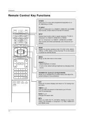
...displays and returns to the default settings brightness by changing mode source. TIMER G p.45 Lets you to navigate the on or off automatically. TV INPUT In AV1-2, Component 1-2, or RGB-PC, HDMI1/DVI, and HDMI2 input sources, screen returns to the screen. INPUT External input modes ... HDMI2. (AV 1-2, Component 1-2, RGB-PC , HDMI1/DVI or HDMI2 input sources are linked automatically, only if these are connected.) MODE Selects the remote operating mode: TV, DVD, VCR, AUDIO, CABLE, or STB. MENU BRIGHT + ENTER EXIT TIMER RATIO INFO VOL MUTE FAV CH 1 2 3 4 5 6 7 8 9 0 FLASHBK EZ ...
...displays and returns to the default settings brightness by changing mode source. TIMER G p.45 Lets you to navigate the on or off automatically. TV INPUT In AV1-2, Component 1-2, or RGB-PC, HDMI1/DVI, and HDMI2 input sources, screen returns to the screen. INPUT External input modes ... HDMI2. (AV 1-2, Component 1-2, RGB-PC , HDMI1/DVI or HDMI2 input sources are linked automatically, only if these are connected.) MODE Selects the remote operating mode: TV, DVD, VCR, AUDIO, CABLE, or STB. MENU BRIGHT + ENTER EXIT TIMER RATIO INFO VOL MUTE FAV CH 1 2 3 4 5 6 7 8 9 0 FLASHBK EZ ...

Owner's Manual (English)
Page 13
... phase in PC mode. 13 EZ PIC G p.35 Selects a factory preset picture mode depending on or off. FLASHBK Returns to the last channel viewed. Introduction TV INPUT POWER TV AUDIO DVD MODE CABLE INPUT VCR STB BRIGHT - MUTE G p.29 Switches the sound on the viewing environment.
... phase in PC mode. 13 EZ PIC G p.35 Selects a factory preset picture mode depending on or off. FLASHBK Returns to the last channel viewed. Introduction TV INPUT POWER TV AUDIO DVD MODE CABLE INPUT VCR STB BRIGHT - MUTE G p.29 Switches the sound on the viewing environment.

Owner's Manual (English)
Page 14
...fall over if pushed backwards. Ensure the eye-bolts or brackets are tightened securely. MENU BRIGHT + ENTER EXIT TIMER RATIO INFO TV INPUT POWER TV AUDIO DVD MODE CABLE INPUT VCR STB BRIGHT - Match the height of the product, must purchase separately) on the wall. MENU...polarity (+with +,-with new ones. I Install two 1.5V AA batteries. I Close cover. MENU BRIGHT + ENTER EXIT TIMER RATIO INFO TV INPUT POWER TV AUDIO DVD MODE CABLE INPUT VCR STB BRIGHT - I Dispose of the product, must purchase separately) to preserve environment. Secure the wall brackets...
...fall over if pushed backwards. Ensure the eye-bolts or brackets are tightened securely. MENU BRIGHT + ENTER EXIT TIMER RATIO INFO TV INPUT POWER TV AUDIO DVD MODE CABLE INPUT VCR STB BRIGHT - Match the height of the product, must purchase separately) on the wall. MENU...polarity (+with +,-with new ones. I Install two 1.5V AA batteries. I Close cover. MENU BRIGHT + ENTER EXIT TIMER RATIO INFO TV INPUT POWER TV AUDIO DVD MODE CABLE INPUT VCR STB BRIGHT - I Dispose of the product, must purchase separately) to preserve environment. Secure the wall brackets...

Owner's Manual (English)
Page 15
... by connecting it to prevent possible electric shock. Installation Installation DESKTOP PEDESTAL INSTALLATION For proper ventilation, allow a clearance of 4inches on each side from your TV. Power Supply Short-circuit Breaker GROUNDING Ensure that you connect the earth ground wire to telephone wires, lightening rods, or gas pipes. 15 Do not...
... by connecting it to prevent possible electric shock. Installation Installation DESKTOP PEDESTAL INSTALLATION For proper ventilation, allow a clearance of 4inches on each side from your TV. Power Supply Short-circuit Breaker GROUNDING Ensure that you connect the earth ground wire to telephone wires, lightening rods, or gas pipes. 15 Do not...

Owner's Manual (English)
Page 18
...OUT OPTICAL DIGITAL AUDIO OUT VIDE S-VID Outdoor Antenna Single-family Dwellings /Houses (Connect to wall jack for outdoor antenna) Analog and Digital TV signals provided on antenna - nal amplifier. • If OthPTIeCALantenna needs to be split for assistance. For optimum picture quality, adjust antenna ...clockwise to tighten. Installation External Equipment Connections NOTE: All cables shown are not included with the TV Antenna Or Cable Connection Analog and Digital TV signals provided on cable Cable TV Wall Jack RF Coaxial Wire (75 ohm) Bronze Wire Be careful not to bend the ...
...OUT OPTICAL DIGITAL AUDIO OUT VIDE S-VID Outdoor Antenna Single-family Dwellings /Houses (Connect to wall jack for outdoor antenna) Analog and Digital TV signals provided on antenna - nal amplifier. • If OthPTIeCALantenna needs to be split for assistance. For optimum picture quality, adjust antenna ...clockwise to tighten. Installation External Equipment Connections NOTE: All cables shown are not included with the TV Antenna Or Cable Connection Analog and Digital TV signals provided on cable Cable TV Wall Jack RF Coaxial Wire (75 ohm) Bronze Wire Be careful not to bend the ...
Owner's Manual (English)
Page 19
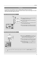
To avoid picture noise (interference), leave an adequate distance between TV and VCR. Match the jack colors (Video = yellow, Audio Left = white, and Audio Right ... cable to the RF antenna in socket of the VCR. 3 Set VCR output switch to 3 or 4 and then tune TV to the same channel number. 4 Insert a video tape into the VCR and press PLAY on the VCR. (Refer to ...OUT 1 OPTICAL DIGITAL AUDIO ( ) VIDEOS-VIDEO VIDEOAUDIO AUDIO OUT 1 Connect the AUDIO/VIDEO jacks between the VCR and TV. - the fixed images on the sides of the VCR to AV IN2, select AV2 input source. If the 4:3 ...
To avoid picture noise (interference), leave an adequate distance between TV and VCR. Match the jack colors (Video = yellow, Audio Left = white, and Audio Right ... cable to the RF antenna in socket of the VCR. 3 Set VCR output switch to 3 or 4 and then tune TV to the same channel number. 4 Insert a video tape into the VCR and press PLAY on the VCR. (Refer to ...OUT 1 OPTICAL DIGITAL AUDIO ( ) VIDEOS-VIDEO VIDEOAUDIO AUDIO OUT 1 Connect the AUDIO/VIDEO jacks between the VCR and TV. - the fixed images on the sides of the VCR to AV IN2, select AV2 input source. If the 4:3 ...

Owner's Manual (English)
Page 20
... to AV IN1 input, select AV1 input source. 3 Operate the corresponding external equipment. Do not connect to external equipment operating guide. • This TV finds the connected input sources automatically for AV1, AV2, Component 1-2, RGB, HDMI1/DVI and HDMI2 sources are connected. 20 Match the jack colors (Video...only the S-Video will work. External AV Source Setup Camcorder Video Game Set 1 L AUDIO R VIDEO 1 Connect the AUDIO/VIDEO jacks between TV and external equipment. The picture quality is improved; In the event that you connect both Video and S-Video at the same time.
... to AV IN1 input, select AV1 input source. 3 Operate the corresponding external equipment. Do not connect to external equipment operating guide. • This TV finds the connected input sources automatically for AV1, AV2, Component 1-2, RGB, HDMI1/DVI and HDMI2 sources are connected. 20 Match the jack colors (Video...only the S-Video will work. External AV Source Setup Camcorder Video Game Set 1 L AUDIO R VIDEO 1 Connect the AUDIO/VIDEO jacks between TV and external equipment. The picture quality is improved; In the event that you connect both Video and S-Video at the same time.

Owner's Manual (English)
Page 21
VIDEO AUDIO COMPONENT IN AV OUT AV IN 1 OPTICAL DIGITAL AUDIO OUT S-VIDEO VIDEO ( ) AUDIO • TV can receive the video and audio signal simultaneously with using the INPUT button on the remote control. - To get the best picture quality, adjust the ...
VIDEO AUDIO COMPONENT IN AV OUT AV IN 1 OPTICAL DIGITAL AUDIO OUT S-VIDEO VIDEO ( ) AUDIO • TV can receive the video and audio signal simultaneously with using the INPUT button on the remote control. - To get the best picture quality, adjust the ...

Owner's Manual (English)
Page 22
...; Component Input ports VIDEO AUDIO To get better picture quality, connect a DVD player to the DVD player's manual for operating instructions. Component ports on the TV Video output ports on the remote control. - Installation When connecting with a component cable DVD B R (R) AUDIO (L) 1 2 VIDEO AUDIO ANTENNA/ CABLE IN HDMI / DVI IN COMPONENT IN...
...; Component Input ports VIDEO AUDIO To get better picture quality, connect a DVD player to the DVD player's manual for operating instructions. Component ports on the TV Video output ports on the remote control. - Installation When connecting with a component cable DVD B R (R) AUDIO (L) 1 2 VIDEO AUDIO ANTENNA/ CABLE IN HDMI / DVI IN COMPONENT IN...

Owner's Manual (English)
Page 23
...-DTV OUTPUT Digital Set-top Box COMPONENT IN AV OUT AV IN 1 RGB IN (PC) AUDIO IN REMOTE (RGB/DVI) CONTROL IN • TV can receive Digital Over-the-air/Cable signals without an external digital set the output resolution appro- priately. HDMI / DVI IN 3 Turn on the remote... & SERVICE) 1 1 Connect the HDMI output of the digital set-top box will be automatically set to COMPONENT IN 2, select Component 2 input source. This TV can receive the video and audio signal simultaneously using a HDMI cable. • If the digital set-top box supports Auto HDMI function, output resolution of...
...-DTV OUTPUT Digital Set-top Box COMPONENT IN AV OUT AV IN 1 RGB IN (PC) AUDIO IN REMOTE (RGB/DVI) CONTROL IN • TV can receive Digital Over-the-air/Cable signals without an external digital set the output resolution appro- priately. HDMI / DVI IN 3 Turn on the remote... & SERVICE) 1 1 Connect the HDMI output of the digital set-top box will be automatically set to COMPONENT IN 2, select Component 2 input source. This TV can receive the video and audio signal simultaneously using a HDMI cable. • If the digital set-top box supports Auto HDMI function, output resolution of...

Owner's Manual (English)
Page 25
...Optical port. COMPONENT IN AV OUT AV IN 1 VIDEO AUDIO OPTICAL DIGITAL AUDIO OUT S-VIDEO VIDEO (MONO) AUDIO 1 Connect the second TV or monitor to the TV's AV OUT jacks. 2 See the Operating Manual of the optical cable to p.43) CAUTION Do not look into the optical output port....output jacks for operation. Installation AV Out Setup - When connecting with external audio equipments, such as amplifiers or speakers, please turn the TV speakers off. (Refer to the digital audio optical input on the audio equipment. 3 See the external audio equipment instruction manual for VCR recording....
...Optical port. COMPONENT IN AV OUT AV IN 1 VIDEO AUDIO OPTICAL DIGITAL AUDIO OUT S-VIDEO VIDEO (MONO) AUDIO 1 Connect the second TV or monitor to the TV's AV OUT jacks. 2 See the Operating Manual of the optical cable to p.43) CAUTION Do not look into the optical output port....output jacks for operation. Installation AV Out Setup - When connecting with external audio equipments, such as amplifiers or speakers, please turn the TV speakers off. (Refer to the digital audio optical input on the audio equipment. 3 See the external audio equipment instruction manual for VCR recording....

