Specification (English)
Page 2
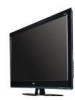
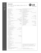
... (WxHxD) 57.3" x 40.2" x 21.3" TV without stand weight 71.7 lbs TV with Deep Color) RGB In (D-Sub 15pin) - LCD TV 55LH40 55" Class Full HD 1080p 120Hz LCD TV (54.6" diagonal) LGusa.com LCD SPECIFICATION Screen Size (Class) 55" Class (54.6" diagonal) Native Display Resolution 1920...Labeling • Quick View (Previous Channel) • Quick Setup Guide • e-Manual • Parental Control w/V-Chip • Key Lock • Closed Caption • LG SIMPLINK (HDMI CEC) • CONVENIENCE FEATURES Language English/Spanish/French/Korean Auto Tuning...
... (WxHxD) 57.3" x 40.2" x 21.3" TV without stand weight 71.7 lbs TV with Deep Color) RGB In (D-Sub 15pin) - LCD TV 55LH40 55" Class Full HD 1080p 120Hz LCD TV (54.6" diagonal) LGusa.com LCD SPECIFICATION Screen Size (Class) 55" Class (54.6" diagonal) Native Display Resolution 1920...Labeling • Quick View (Previous Channel) • Quick Setup Guide • e-Manual • Parental Control w/V-Chip • Key Lock • Closed Caption • LG SIMPLINK (HDMI CEC) • CONVENIENCE FEATURES Language English/Spanish/French/Korean Auto Tuning...

Owner's Manual (English)
Page 1
...User 1-888-865-3026 USA, Commercial User 1-888-542-2623 CANADA LG Customer Information Center P/NO : SAC33601903 (0910-REV04) www.lgusa.com / www.lg.ca LCD TV OWNER'S MANUAL 32LH40 37LH40 42LH40 47LH40 55LH40 32LH41 37LH41 42LH41 47LH41 55LH41 37LH55 42LH55 47LH55 55LH55 32CL40 42CL40 47CL40... 55LH400C Please read this manual carefully before operating your set and retain it below should ...
...User 1-888-865-3026 USA, Commercial User 1-888-542-2623 CANADA LG Customer Information Center P/NO : SAC33601903 (0910-REV04) www.lgusa.com / www.lg.ca LCD TV OWNER'S MANUAL 32LH40 37LH40 42LH40 47LH40 55LH40 32LH41 37LH41 42LH41 47LH41 55LH41 37LH55 42LH55 47LH55 55LH55 32CL40 42CL40 47CL40... 55LH400C Please read this manual carefully before operating your set and retain it below should ...
Owner's Manual (English)
Page 4
... Check the specification page of this apparatus or antenna during a thunder or lighting storm. on the power cord to unplug the TV. 4 15 WARNING - a TV with an exact replacement part by the hanging power and signal cables on or over the apparatus (e.g. Do not connect too many ... methods are dangerous. Do not use of these conditions could result in electric shock or fire. SAFETY INSTRUCTIONS 11 Never touch this owner's manual to be certain. Any of the appliance, and have a qualified electrician install a separate circuit breaker. Do not pull on shelves above ...
... Check the specification page of this apparatus or antenna during a thunder or lighting storm. on the power cord to unplug the TV. 4 15 WARNING - a TV with an exact replacement part by the hanging power and signal cables on or over the apparatus (e.g. Do not connect too many ... methods are dangerous. Do not use of these conditions could result in electric shock or fire. SAFETY INSTRUCTIONS 11 Never touch this owner's manual to be certain. Any of the appliance, and have a qualified electrician install a separate circuit breaker. Do not pull on shelves above ...
Owner's Manual (English)
Page 6
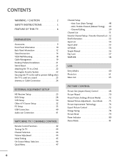
... 50 Channel List 51 Favorite Channel Setup / Favorite Channel List . . 52 Brief Information 53 Input List 54 Input Label 55 AV Mode 56 Simple Manual 56 Key Lock 57 SIMPLINK 58 USB Entry Modes 60 Photo List 61 Music List 65 PICTURE CONTROL Picture Size (Aspect Ratio... 75 Energy Saving 78 Picture Reset 79 Power Indicator 80 Demo Mode 81 CONTENTS WARNING / CAUTION 2 SAFETY INSTRUCTIONS 3 FEATURE OF THIS TV 8 PREPARATION Accessories 9 Front Panel Information 10 Back Panel Information 12 Stand Instruction 14 VESA Wall Mounting 18 Cable Management 19 Desktop Pedestal ...
... 50 Channel List 51 Favorite Channel Setup / Favorite Channel List . . 52 Brief Information 53 Input List 54 Input Label 55 AV Mode 56 Simple Manual 56 Key Lock 57 SIMPLINK 58 USB Entry Modes 60 Photo List 61 Music List 65 PICTURE CONTROL Picture Size (Aspect Ratio... 75 Energy Saving 78 Picture Reset 79 Power Indicator 80 Demo Mode 81 CONTENTS WARNING / CAUTION 2 SAFETY INSTRUCTIONS 3 FEATURE OF THIS TV 8 PREPARATION Accessories 9 Front Panel Information 10 Back Panel Information 12 Stand Instruction 14 VESA Wall Mounting 18 Cable Management 19 Desktop Pedestal ...

Owner's Manual (English)
Page 7
...- Digital Broadcasting System Captions 93 - Auto Clock Setup 95 Manual Clock Setup 96 Auto On/Off Time Setting 97 Sleep Timer Setting 98 PARENTAL CONTROL / RATINGS Set Password & Lock System 99 Channel Blocking 102 Movie & TV Rating 103 Downloadable Rating 108 External Input Blocking 109 APPENDIX Troubleshooting...Auto Volume 82 Clear Voice II 83 Preset Sound Setting (Sound Mode 84 Sound Setting Adjustment - User Mode 85 Balance 86 TV Speakers On/Off Setup 87 Audio Reset 88 Stereo/SAP Broadcasts Setup 89 Audio Language 90 On-Screen Menus Language Selection 91 Caption Mode ...
...- Digital Broadcasting System Captions 93 - Auto Clock Setup 95 Manual Clock Setup 96 Auto On/Off Time Setting 97 Sleep Timer Setting 98 PARENTAL CONTROL / RATINGS Set Password & Lock System 99 Channel Blocking 102 Movie & TV Rating 103 Downloadable Rating 108 External Input Blocking 109 APPENDIX Troubleshooting...Auto Volume 82 Clear Voice II 83 Preset Sound Setting (Sound Mode 84 Sound Setting Adjustment - User Mode 85 Balance 86 TV Speakers On/Off Setup 87 Audio Reset 88 Stereo/SAP Broadcasts Setup 89 Audio Language 90 On-Screen Menus Language Selection 91 Caption Mode ...
Owner's Manual (English)
Page 9
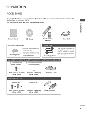
Excessive pressure may differ from the images below. For 32/37/42/47/55LH40, 32/37/42/47/55LH41, 37/42/47/55LH55, 55LH400C (Except 55LH40, 55LH41, 55LH55, 55LH400C) (Except 47/55LH40, 47/55LH41, 47/55LH55, 55LH400C) x 4 Bolts for stand assembly Screw for stand ... is missing, please contact the dealer where you purchased the TV. MESNLUEEPRATIO MENU POWER ENERGYINSAVPINUG T RETURN INFO ENTER VOL FAMVARK AV MODE 1 4 MUTE 2 CH P A G E 7 5 3 8 6 LIST 0 9 FLASHBK 1.5V 1.5V Owner's Manual CD Manual Remote Control, Batteries Power Cord Not included with all models ...
Excessive pressure may differ from the images below. For 32/37/42/47/55LH40, 32/37/42/47/55LH41, 37/42/47/55LH55, 55LH400C (Except 55LH40, 55LH41, 55LH55, 55LH400C) (Except 47/55LH40, 47/55LH41, 47/55LH55, 55LH400C) x 4 Bolts for stand assembly Screw for stand ... is missing, please contact the dealer where you purchased the TV. MESNLUEEPRATIO MENU POWER ENERGYINSAVPINUG T RETURN INFO ENTER VOL FAMVARK AV MODE 1 4 MUTE 2 CH P A G E 7 5 3 8 6 LIST 0 9 FLASHBK 1.5V 1.5V Owner's Manual CD Manual Remote Control, Batteries Power Cord Not included with all models ...
Owner's Manual (English)
Page 18
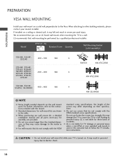
...cause damage to the inside to a wall. G Do not use an LG brand wall mount when mounting the TV to the TV. We recommend that you use screws that do not comply with the ...VESA standard screw specifications, the length of accidents. NOTE G Screw length needed depends on their specifications. G When purchasing our wall mount kit, a detailed installation manual... 42LH55, 42CL40, 47LH40, 200 * 200 M6 4 47LH41, 47LH55, 47CL40 AW-47LG30M 55LH40, 55LH41, 55LH55, 55LH400C 400 * 400 M6 4 AW-55LH40M !
...cause damage to the inside to a wall. G Do not use an LG brand wall mount when mounting the TV to the TV. We recommend that you use screws that do not comply with the ...VESA standard screw specifications, the length of accidents. NOTE G Screw length needed depends on their specifications. G When purchasing our wall mount kit, a detailed installation manual... 42LH55, 42CL40, 47LH40, 200 * 200 M6 4 47LH41, 47LH55, 47CL40 AW-47LG30M 55LH40, 55LH41, 55LH55, 55LH400C 400 * 400 M6 4 AW-55LH40M !
Owner's Manual (English)
Page 21
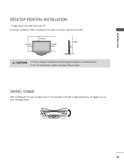
G Do not mount near or above any type of 4 inches on all four sides from your viewing position. 21 SWIVEL STAND After installing the TV, you can adjust the TV set manually to the left or right direction by following the clearance recommendations. For proper ventilation, allow a clearance of heat source. PREPARATION DESKTOP PEDESTAL INSTALLATION I Image shown may differ from the wall. 4 inches 4 inches 4 inches 4 inches CAUTION G Ensure adequate ventilation by 20 degrees to suit your TV.
G Do not mount near or above any type of 4 inches on all four sides from your viewing position. 21 SWIVEL STAND After installing the TV, you can adjust the TV set manually to the left or right direction by following the clearance recommendations. For proper ventilation, allow a clearance of heat source. PREPARATION DESKTOP PEDESTAL INSTALLATION I Image shown may differ from the wall. 4 inches 4 inches 4 inches 4 inches CAUTION G Ensure adequate ventilation by 20 degrees to suit your TV.

Owner's Manual (English)
Page 25
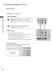
... PB, PR) of the digital set -top box operation.) I Select the Component1 input source on the TV using the INPUT button on the TV. How to use I Turn on the digital set-top box. (Refer to the owner's manual for the digital set -top box to 2 the COMPONENT IN AUDIO 1 jacks on the... TV. 1 2 AV IN 1 VIDEO L(MONO) AUDIO R 3 2 2 L R 1 1 VIDEO AUDIO COMPONENT IN /DVI IN Supported Resolutions Signal 480i 480p 720p 1080i 1080p Component Yes Yes...
... PB, PR) of the digital set -top box operation.) I Select the Component1 input source on the TV using the INPUT button on the TV. How to use I Turn on the digital set-top box. (Refer to the owner's manual for the digital set -top box to 2 the COMPONENT IN AUDIO 1 jacks on the... TV. 1 2 AV IN 1 VIDEO L(MONO) AUDIO R 3 2 2 L R 1 1 VIDEO AUDIO COMPONENT IN /DVI IN Supported Resolutions Signal 480i 480p 720p 1080i 1080p Component Yes Yes...

Owner's Manual (English)
Page 26
... 60.00 26 EXTERNAL EQUIPMENT SETUP ( ) HDMI Connection 1. In this case use I Turn on the digital set-top box. (Refer to the owner's manual for the digital set -top box to use the latest cables that support HDMI version 1.3. HDMI supports both audio and video. 2. AV IN 1 VIDEO L(...connect EXTERNAL EQUIPMENT SETUP 1 Connect the digital set -top box.) I Select the HDMI1, HDMI2, HDMI3, or HDMI4 input source on the TV using the INPUT button on the TV. 2 No separate audio connection is necessary. If the HDMI cables don't support HDMI version 1.3, it can cause flickers or no screen ...
... 60.00 26 EXTERNAL EQUIPMENT SETUP ( ) HDMI Connection 1. In this case use I Turn on the digital set-top box. (Refer to the owner's manual for the digital set -top box to use the latest cables that support HDMI version 1.3. HDMI supports both audio and video. 2. AV IN 1 VIDEO L(...connect EXTERNAL EQUIPMENT SETUP 1 Connect the digital set -top box.) I Select the HDMI1, HDMI2, HDMI3, or HDMI4 input source on the TV using the INPUT button on the TV. 2 No separate audio connection is necessary. If the HDMI cables don't support HDMI version 1.3, it can cause flickers or no screen ...

Owner's Manual (English)
Page 27
... HDMI1, HDMI2, or HDMI3 input source on the TV using the INPUT button on the TV. 2. NOTE G A DVI to the HDMI/DVI IN 1, 2, or 3 jack on the TV. 2 Connect the digital set -top box.) I Turn on the digital set-top box. (Refer to the owner's manual for this connection. AV IN 1 L(MONO) AUDIO R 3 2 L R 1 AUDIO...
... HDMI1, HDMI2, or HDMI3 input source on the TV using the INPUT button on the TV. 2. NOTE G A DVI to the HDMI/DVI IN 1, 2, or 3 jack on the TV. 2 Connect the digital set -top box.) I Turn on the digital set-top box. (Refer to the owner's manual for this connection. AV IN 1 L(MONO) AUDIO R 3 2 L R 1 AUDIO...
Owner's Manual (English)
Page 28
How to use I Refer to the DVD player's manual for operating instructions. I Turn on the TV. Component ports on the TV Y PB PR Video output ports on the remote control. Match the jack colors (Y = green, PB = blue, and PR = red). 2 Connect the audio outputs ... connect 1 Connect the video outputs (Y, PB, PR) of the DVD to the component input ports as shown below. I Select the Component1 input source on the TV using the INPUT button on DVD player Y PB PR Y B-Y R-Y Y Cb Cr Y Pb Pr Y PB PR L R 1 2 AV IN 1 /DVI VIDEO L(MONO) AUDIO R 3 2 2 L R 1 1 VIDEO ...
How to use I Refer to the DVD player's manual for operating instructions. I Turn on the TV. Component ports on the TV Y PB PR Video output ports on the remote control. Match the jack colors (Y = green, PB = blue, and PR = red). 2 Connect the audio outputs ... connect 1 Connect the video outputs (Y, PB, PR) of the DVD to the component input ports as shown below. I Select the Component1 input source on the TV using the INPUT button on DVD player Y PB PR Y B-Y R-Y Y Cb Cr Y Pb Pr Y PB PR L R 1 2 AV IN 1 /DVI VIDEO L(MONO) AUDIO R 3 2 2 L R 1 1 VIDEO ...

Owner's Manual (English)
Page 29
...Left = white, and Audio Right = red) 2. I Turn on the remote control. How to connect 1 Connect the AUDIO/VIDEO jacks between TV and DVD. HDMI Connection 1. How to the HDMI/DVI IN 1, 2, 3 or 4 jack on the remote control. How to connect 1 ... both audio and video. 2. If the HDMI cables don't support HDMI version 1.3, it can cause flickers or no screen display. I Refer to the DVD player's manual for operating instructions. ! AV IN 1 VIDEO L(MONO) AUDIO R 3 2 1 ( ) 2 L R 1 VIDEO AUDIO COMPONENT IN /DVI IN 1 VIDEO L R AUDIO ( ) AV IN 1 VIDEO L(MONO)...
...Left = white, and Audio Right = red) 2. I Turn on the remote control. How to connect 1 Connect the AUDIO/VIDEO jacks between TV and DVD. HDMI Connection 1. How to the HDMI/DVI IN 1, 2, 3 or 4 jack on the remote control. How to connect 1 ... both audio and video. 2. If the HDMI cables don't support HDMI version 1.3, it can cause flickers or no screen display. I Refer to the DVD player's manual for operating instructions. ! AV IN 1 VIDEO L(MONO) AUDIO R 3 2 1 ( ) 2 L R 1 VIDEO AUDIO COMPONENT IN /DVI IN 1 VIDEO L R AUDIO ( ) AV IN 1 VIDEO L(MONO)...

Owner's Manual (English)
Page 30
... 1 ANTENNA/ RS-232C IN CABLE IN (CONTROL&SERVICE) 2 Connect the antenna cable to the RF antenna in socket of the VCR to the VCR owner's manual.) ANT OUT S-VIDEO VIDEO L R AUDIO ANT IN OUTPUT SWITCH Wall Jack 2 Antenna 30 How to use I Insert a video tape into the VCR and ... IN OPTICAL DIGITAL AUDIO OUT et on the VCR. (Refer to the ANTENNA/CABLE IN sock- I Set VCR output switch to 3 or 4 and then tune TV to connect ( ) RGB IN (PC) 1 Connect the RF antenna out socket of the VCR. 2. EXTERNAL EQUIPMENT SETUP EXTERNAL EQUIPMENT SETUP VCR SETUP Antenna Connection...
... 1 ANTENNA/ RS-232C IN CABLE IN (CONTROL&SERVICE) 2 Connect the antenna cable to the RF antenna in socket of the VCR to the VCR owner's manual.) ANT OUT S-VIDEO VIDEO L R AUDIO ANT IN OUTPUT SWITCH Wall Jack 2 Antenna 30 How to use I Insert a video tape into the VCR and ... IN OPTICAL DIGITAL AUDIO OUT et on the VCR. (Refer to the ANTENNA/CABLE IN sock- I Set VCR output switch to 3 or 4 and then tune TV to connect ( ) RGB IN (PC) 1 Connect the RF antenna out socket of the VCR. 2. EXTERNAL EQUIPMENT SETUP EXTERNAL EQUIPMENT SETUP VCR SETUP Antenna Connection...
Owner's Manual (English)
Page 31
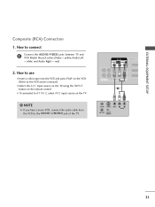
NOTE G If you have a mono VCR, connect the audio cable from the VCR to the VCR owner's manual.) I Select the A V 1 input source on the TV using the INPUT button on the remote control. Match the jack colors (Video = yellow, Audio Left = white, and Audio Right = ...) 2. EXTERNAL EQUIPMENT SETUP Composite (RCA) Connection 1. How to use I If connected to connect 1 Connect the AUDIO/VIDEO jacks between TV and VCR. I Insert a video tape into the VCR and press PLAY on the TV. ! AV IN 1 /DVI VIDEO L(MONO) AUDIO R 3 2 2 L R 1 1 VIDEO AUDIO COMPONENT IN 1 ANT IN S-VIDEO...
NOTE G If you have a mono VCR, connect the audio cable from the VCR to the VCR owner's manual.) I Select the A V 1 input source on the TV using the INPUT button on the remote control. Match the jack colors (Video = yellow, Audio Left = white, and Audio Right = ...) 2. EXTERNAL EQUIPMENT SETUP Composite (RCA) Connection 1. How to use I If connected to connect 1 Connect the AUDIO/VIDEO jacks between TV and VCR. I Insert a video tape into the VCR and press PLAY on the TV. ! AV IN 1 /DVI VIDEO L(MONO) AUDIO R 3 2 2 L R 1 1 VIDEO AUDIO COMPONENT IN 1 ANT IN S-VIDEO...

Owner's Manual (English)
Page 37
...; Advanced Control • Picture Reset Screen (RGB-PC) 1 MENU 2 ENTER 3 ENTER Select PICTURE. After adjustment, if the image is still not correct, try using the manual settings or a different resolution or refresh rate on the PC. Select Screen (RGB-PC). I If the position of the image is still not correct, try...
...; Advanced Control • Picture Reset Screen (RGB-PC) 1 MENU 2 ENTER 3 ENTER Select PICTURE. After adjustment, if the image is still not correct, try using the manual settings or a different resolution or refresh rate on the PC. Select Screen (RGB-PC). I If the position of the image is still not correct, try...

Owner's Manual (English)
Page 38
... 2 ENTER 3 ENTER 4 ENTER 5 ENTER Select PICTURE. I S i z e: This function is not clear after auto adjustment and especially if characters are still trembling, adjust the picture phase manually. Select Screen (RGB-PC).
... 2 ENTER 3 ENTER 4 ENTER 5 ENTER Select PICTURE. I S i z e: This function is not clear after auto adjustment and especially if characters are still trembling, adjust the picture phase manually. Select Screen (RGB-PC).

Owner's Manual (English)
Page 41
...Do not look into the optical output port. How to connect 1 Connect one end of the optical cable to the TV port of OPTICAL DIGITAL AUDIO OUT. 2 Connect the other end of TV to the digital audio input on the back of the optical cable to a Home Theater (or amp). 1. G...OUT CONNECTION Send the TV's audio to external audio equipment via the Audio Output port. Looking at the laser beam may block digital audio output. 41 NOTE G When connecting with ACP (Audio Copy Protection) function may damage your vision. See the external audio equipment instruction manual for operation. /DVI...
...Do not look into the optical output port. How to connect 1 Connect one end of the optical cable to the TV port of OPTICAL DIGITAL AUDIO OUT. 2 Connect the other end of TV to the digital audio input on the back of the optical cable to a Home Theater (or amp). 1. G...OUT CONNECTION Send the TV's audio to external audio equipment via the Audio Output port. Looking at the laser beam may block digital audio output. 41 NOTE G When connecting with ACP (Audio Copy Protection) function may damage your vision. See the external audio equipment instruction manual for operation. /DVI...

Owner's Manual (English)
Page 45
... displaying at Store, select [Store Demo]. "Store Demo" mode initializes the TV to easily set the image quality. To use this TV at stores. I Default selection is connected. 1 ENTER Previous INFO i Simple Manual Next Check your home environment. I You can also adjust Initial Setting in ... 10 AM 10 Eastern Auto Previous Next 1 Select Auto or Manual. 2 ENTER Select desired time option. Picture mode" manually while inspecting the TV, but the TV will be displayed on the screen when turning the TV on for the best picture in your antenna connection and start Auto...
... displaying at Store, select [Store Demo]. "Store Demo" mode initializes the TV to easily set the image quality. To use this TV at stores. I Default selection is connected. 1 ENTER Previous INFO i Simple Manual Next Check your home environment. I You can also adjust Initial Setting in ... 10 AM 10 Eastern Auto Previous Next 1 Select Auto or Manual. 2 ENTER Select desired time option. Picture mode" manually while inspecting the TV, but the TV will be displayed on the screen when turning the TV on for the best picture in your antenna connection and start Auto...

Owner's Manual (English)
Page 46
... CONTROL ON-SCREEN MENUS SELECTION Your TV's OSD (On Screen Display) may differ slightly from that shown in this manual. CHANNEL Auto Tuning Manual Tuning Channel Edit Move Enter PICTURE Move Enter Aspect Ratio : 16:9 Picture Wizard Energy Saving : Off Picture Mode : ...0L R Sound Mode : Standard • SRS TruSurround XT: Off • Treble 50 • Bass 50 E WATCHING TV / CHANNEL CONTROL OPTION Menu Language Audio Language Input Label SIMPLINK Key Lock Simple Manual Caption Set ID E Move Enter : English : English : On : Off : Off : 1 CHANNEL PICTURE AUDIO TIME OPTION...
... CONTROL ON-SCREEN MENUS SELECTION Your TV's OSD (On Screen Display) may differ slightly from that shown in this manual. CHANNEL Auto Tuning Manual Tuning Channel Edit Move Enter PICTURE Move Enter Aspect Ratio : 16:9 Picture Wizard Energy Saving : Off Picture Mode : ...0L R Sound Mode : Standard • SRS TruSurround XT: Off • Treble 50 • Bass 50 E WATCHING TV / CHANNEL CONTROL OPTION Menu Language Audio Language Input Label SIMPLINK Key Lock Simple Manual Caption Set ID E Move Enter : English : English : On : Off : Off : 1 CHANNEL PICTURE AUDIO TIME OPTION...


