
Owners Manual
Page 1
LCD TV MODELS 32LB9D* 42LB9DF* 47LB9DF* 52LB9DF* PLASMA TV MODELS 50PY3DF* 60PY3DF* 42PB4D* 50PB4D* DVB is a registered trademark of the DVB Project ID Number: 4757: 32LB9D 4756: 42LB9DF 4755: 47LB9DF 4754: 52LB9DF 4709: 50PY3DF 4708: 60PY3DF 4836: 42PB4D 4837: 50PB4D O N L Y :42LB9DF 47LB9DF 52LB9DF 50PY3DF 60PY3DF
LCD TV MODELS 32LB9D* 42LB9DF* 47LB9DF* 52LB9DF* PLASMA TV MODELS 50PY3DF* 60PY3DF* 42PB4D* 50PB4D* DVB is a registered trademark of the DVB Project ID Number: 4757: 32LB9D 4756: 42LB9DF 4755: 47LB9DF 4754: 52LB9DF 4709: 50PY3DF 4708: 60PY3DF 4836: 42PB4D 4837: 50PB4D O N L Y :42LB9DF 47LB9DF 52LB9DF 50PY3DF 60PY3DF
Owners Manual
Page 3
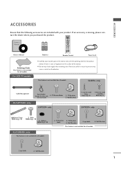
...p. 9 50PY3DF* only Additional Cover Refer to p. 10 4-bolts for the product exterior if there is not available for all models. 2- TV Brackets, Bolts 2- tact the dealer where you purchased the product. Wall Brackets 60PY3DF* only 1-screw for stand fixing Refer to p. 16 3...MUTE 1 2 3 4 5 6 7 8 9 LIST 0 FAV SIZE ? ACCESSORIES ACCESSORIES Ensure that the following accessories are included with 2- For LCD TV models I Carefully wipe stained spot on the surface of the exterior. REVEAL INDEX I Do not wipe hard roughly when removing stain. I /II TIME USB...
...p. 9 50PY3DF* only Additional Cover Refer to p. 10 4-bolts for the product exterior if there is not available for all models. 2- TV Brackets, Bolts 2- tact the dealer where you purchased the product. Wall Brackets 60PY3DF* only 1-screw for stand fixing Refer to p. 16 3...MUTE 1 2 3 4 5 6 7 8 9 LIST 0 FAV SIZE ? ACCESSORIES ACCESSORIES Ensure that the following accessories are included with 2- For LCD TV models I Carefully wipe stained spot on the surface of the exterior. REVEAL INDEX I Do not wipe hard roughly when removing stain. I /II TIME USB...
Owners Manual
Page 4
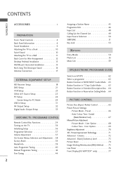
... 71 Advanced - CONTENTS CONTENTS ACCESSORIES 1 PREPARATION i Front Panel Controls 4 Back Panel Information 6 Stand Installation 9 Attaching the TV to a Desk 10 Swivel Stand 10 Attaching the TV to a Wall 11 Back Cover for PC Mode 29 USB In Setup 31 AV Output Setup 32 Digital Audio Output Setup... 33 WATCHING TV / PROGRAMME CONTROL Remote Control Key Functions 34 Turning on the TV 36 Initializing Setup 36 Programme Selection 37 Volume Adjustment 37 On-Screen Menus Selection and Adjustment . ...
... 71 Advanced - CONTENTS CONTENTS ACCESSORIES 1 PREPARATION i Front Panel Controls 4 Back Panel Information 6 Stand Installation 9 Attaching the TV to a Desk 10 Swivel Stand 10 Attaching the TV to a Wall 11 Back Cover for PC Mode 29 USB In Setup 31 AV Output Setup 32 Digital Audio Output Setup... 33 WATCHING TV / PROGRAMME CONTROL Remote Control Key Functions 34 Turning on the TV 36 Initializing Setup 36 Programme Selection 37 Volume Adjustment 37 On-Screen Menus Selection and Adjustment . ...

Owners Manual
Page 5
... Special Teletext Functions 97 After reading this manual, keep it handy for future reference. 3 Sound Mode 79 Sound Setting Adjustment - User Mode 80 Balance 82 TV Speakers On/ Off Setup 83 I/II -
... Special Teletext Functions 97 After reading this manual, keep it handy for future reference. 3 Sound Mode 79 Sound Setting Adjustment - User Mode 80 Balance 82 TV Speakers On/ Off Setup 83 I/II -

Owners Manual
Page 6
... the front panel. I This is switched on. INPUT Button POWER Button OK Button VOLUME MENU Button (F,G) Buttons PROGRAMME (E,D) Buttons 4 PREPARATION FRONT PANEL CONTROLS I If your TV.
... the front panel. I This is switched on. INPUT Button POWER Button OK Button VOLUME MENU Button (F,G) Buttons PROGRAMME (E,D) Buttons 4 PREPARATION FRONT PANEL CONTROLS I If your TV.
Owners Manual
Page 9
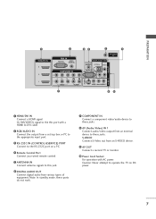
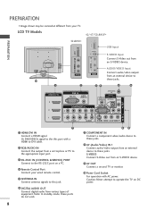
... attempt to these ports do not work. 7 AUDIO S-VIDEO VIDEO ( ) AUDIO 6 DIGITAL AUDIO OUT Connect digital audio from an S-VIDEO device. device to operate the TV on a PC. PREPARATION 1 HDMI/DVI IN 3 2 1 2 RGB IN RGB (PC) AUDIO (RGB/DVI) COMPONENT IN 34 5 6 ANTENNA IN DIGITAL AUDIO OUT...this port with AC power. AUDIO OUT REMOTE CONTROL IN OPTICAL VIDEO 9 AV OUT AV OUT 4 Remote Control Port COMPONENT IN ConRnS-2e32cCtINa second TV or monitor. (CONTROL & SERVICE) Connect your wired remote control. 10 Power Cord Socket 5 ANTENNA IN Connect antenna signals to the RS-232C...
... attempt to these ports do not work. 7 AUDIO S-VIDEO VIDEO ( ) AUDIO 6 DIGITAL AUDIO OUT Connect digital audio from an S-VIDEO device. device to operate the TV on a PC. PREPARATION 1 HDMI/DVI IN 3 2 1 2 RGB IN RGB (PC) AUDIO (RGB/DVI) COMPONENT IN 34 5 6 ANTENNA IN DIGITAL AUDIO OUT...this port with AC power. AUDIO OUT REMOTE CONTROL IN OPTICAL VIDEO 9 AV OUT AV OUT 4 Remote Control Port COMPONENT IN ConRnS-2e32cCtINa second TV or monitor. (CONTROL & SERVICE) Connect your wired remote control. 10 Power Cord Socket 5 ANTENNA IN Connect antenna signals to the RS-232C...
Owners Manual
Page 10
...-232C IN (CONTROL &SERVICE) PORT Connect S-Video out from an S-VIDEO device. Never attemDIGpITtALto AUDIO OUT operate the TV on a PC. 9 AV OUT 4 Remote Control Port Connect a second TV or monitor. Or DVI(VIDEO) signal to the this jack. Connect a component video/audio device to these jacks. ...equipment. For operation with a HDMI to this port with AACNTEpNoNwAer. RGB IN RGB (PC) IN Caution: (RAGUBD/DIOVIp) ower. LCD TV Models 42/47/52LB9DF* USB IN S-VIDEO USB IN 32LB9D* USB IN S-VIDEO USB Input S-VIDEO Input Connect S-Video out from an S-VIDEO device. VIDEO...
...-232C IN (CONTROL &SERVICE) PORT Connect S-Video out from an S-VIDEO device. Never attemDIGpITtALto AUDIO OUT operate the TV on a PC. 9 AV OUT 4 Remote Control Port Connect a second TV or monitor. Or DVI(VIDEO) signal to the this jack. Connect a component video/audio device to these jacks. ...equipment. For operation with a HDMI to this port with AACNTEpNoNwAer. RGB IN RGB (PC) IN Caution: (RAGUBD/DIOVIp) ower. LCD TV Models 42/47/52LB9DF* USB IN S-VIDEO USB IN 32LB9D* USB IN S-VIDEO USB Input S-VIDEO Input Connect S-Video out from an S-VIDEO device. VIDEO...
Owners Manual
Page 12
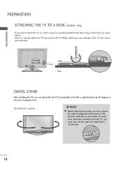
... serious personal injury. 1-screw Stand Desk SWIVEL STAND After installing the TV, you can adjust the the TV set the hole. 10 PREPARATION PREPARATION ATTACHING THE TV TO A DESK (32LB9D* Only) If you must remove the cable management and loosen (to the left or right direction by 20 degrees to suit your ...viewing position. 50/60PY3DF* models NOTE G Before adjusting the angle, you wish to attach the TV to a desk, it must close (to the right) the shaft bolt to set manually to the left ) the shaft bolt on the middle of stand...
... serious personal injury. 1-screw Stand Desk SWIVEL STAND After installing the TV, you can adjust the the TV set the hole. 10 PREPARATION PREPARATION ATTACHING THE TV TO A DESK (32LB9D* Only) If you must remove the cable management and loosen (to the left or right direction by 20 degrees to suit your ...viewing position. 50/60PY3DF* models NOTE G Before adjusting the angle, you wish to attach the TV to a desk, it must close (to the right) the shaft bolt to set manually to the left ) the shaft bolt on the middle of stand...

Owners Manual
Page 13
... picture. (If your product has the bolts in the eye-bolts position before inserting the eye-bolts, loosen the bolts.) * Insert the eye-bolts or TV brackets/bolts and tighten them securely in the forward direction. It is not available for all models. PREPARATION ATTACHING THE... wall as parts of the bracket that children don't climb on or hang from the product. 60PY3DF* 1 50PY3DF* 1 2 42/50PB4D* 1 2 42/47/52LB9DF*, 32LB9D* 1 2 2 1 Use the eye-bolts or TV brackets/bolts to fix the product to tie the product. Please make sure that is pushed backwards. Match the height of the...
... picture. (If your product has the bolts in the eye-bolts position before inserting the eye-bolts, loosen the bolts.) * Insert the eye-bolts or TV brackets/bolts and tighten them securely in the forward direction. It is not available for all models. PREPARATION ATTACHING THE... wall as parts of the bracket that children don't climb on or hang from the product. 60PY3DF* 1 50PY3DF* 1 2 42/50PB4D* 1 2 42/47/52LB9DF*, 32LB9D* 1 2 2 1 Use the eye-bolts or TV brackets/bolts to fix the product to tie the product. Please make sure that is pushed backwards. Match the height of the...
Owners Manual
Page 14
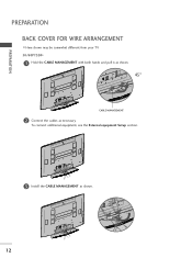
To connect additional equipment, see the External equipment Setup section. 3 Install the CABLE MANAGEMENT as necessary. PREPARATION PREPARATION BACK COVER FOR WIRE ARRANGEMENT I Here shown may be somewhat different from your TV. 50/60PY3DF* 1 Hold the CABLE MANAGEMENT with both hands and pull it as shown. 45° CABLE MANAGEMENT 2 Connect the cables as shown. 12
To connect additional equipment, see the External equipment Setup section. 3 Install the CABLE MANAGEMENT as necessary. PREPARATION PREPARATION BACK COVER FOR WIRE ARRANGEMENT I Here shown may be somewhat different from your TV. 50/60PY3DF* 1 Hold the CABLE MANAGEMENT with both hands and pull it as shown. 45° CABLE MANAGEMENT 2 Connect the cables as shown. 12
Owners Manual
Page 19
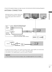
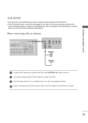
... you know when the analogue, cable, and digital programme scans are complete. 17 I If the antenna is not installed properly, contact your dealer for two TV's, install a 2-Way Signal Splitter. VIDEO L/MONO AUDIO R USB AV IN 2 S-VIDEO AV IN 2 S-VIDEO VIDEO L/MONO AUDIO R USB IN AV IN 2 Wall Antenna Socket Outdoor..., please purchase a signal amplifier and install properly. ANTENNA CONNECTION VIDEO L/MONO AUDIO R USB Wall Antenna Socket or Outdoor Antenna without a Cable Box Connections. NOTE G The TV will let you have finished connecting all equipment.
... you know when the analogue, cable, and digital programme scans are complete. 17 I If the antenna is not installed properly, contact your dealer for two TV's, install a 2-Way Signal Splitter. VIDEO L/MONO AUDIO R USB AV IN 2 S-VIDEO AV IN 2 S-VIDEO VIDEO L/MONO AUDIO R USB IN AV IN 2 Wall Antenna Socket Outdoor..., please purchase a signal amplifier and install properly. ANTENNA CONNECTION VIDEO L/MONO AUDIO R USB Wall Antenna Socket or Outdoor Antenna without a Cable Box Connections. NOTE G The TV will let you have finished connecting all equipment.

Owners Manual
Page 20
...-top box to the COMPONENT IN AUDIO 1 jacks on the set. 3 Turn on the set -top box. (Refer to the owner's manual for the LCD TV models. Match the jack colours. (Y = green, PB = blue, and PR = red) 2 Connect the audio output of the digital set top box to COMPONENT IN 2 input...
...-top box to the COMPONENT IN AUDIO 1 jacks on the set. 3 Turn on the set -top box. (Refer to the owner's manual for the LCD TV models. Match the jack colours. (Y = green, PB = blue, and PR = red) 2 Connect the audio output of the digital set top box to COMPONENT IN 2 input...
Owners Manual
Page 23
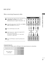
... S 1 2 Y PB PR L R Component Input ports To get better picture quality, connect a DVD player to the DVD player's manual for operating instruc- Component ports on the TV Y PB PR Video output ports on the remote control. NENT IN AUDIO1 jacks on the set . Match the jack colours (Y = green, PB = blue, and PR...
... S 1 2 Y PB PR L R Component Input ports To get better picture quality, connect a DVD player to the DVD player's manual for operating instruc- Component ports on the TV Y PB PR Video output ports on the remote control. NENT IN AUDIO1 jacks on the set . Match the jack colours (Y = green, PB = blue, and PR...
Owners Manual
Page 25
...I If the 4:3 picture format is common to all manufacturers and in socket of the VCR. 3 Set VCR output switch to 3 or 4 and then tune TV to the same programme number. 4 Insert a video tape into the VCR and press PLAY on the VCR. (Refer to the RF antenna in consequence the... does not cover the product bearing this phenomenon. This phenomenon is used; I To avoid picture noise (interference), leave an adequate distance between the VCR and TV. R HDMI/DVI IN RGB When connecting with an antenna C 2 EXTERNAL EQUIPMENT SETUP HDMI/DVI IN 2 1 (DVI) RGB IN RGB (PC) AUDIO (RGB/DVI) ...
...I If the 4:3 picture format is common to all manufacturers and in socket of the VCR. 3 Set VCR output switch to 3 or 4 and then tune TV to the same programme number. 4 Insert a video tape into the VCR and press PLAY on the VCR. (Refer to the RF antenna in consequence the... does not cover the product bearing this phenomenon. This phenomenon is used; I To avoid picture noise (interference), leave an adequate distance between the VCR and TV. R HDMI/DVI IN RGB When connecting with an antenna C 2 EXTERNAL EQUIPMENT SETUP HDMI/DVI IN 2 1 (DVI) RGB IN RGB (PC) AUDIO (RGB/DVI) ...
Owners Manual
Page 26
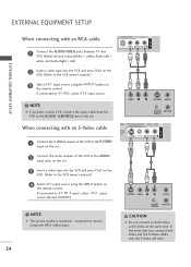
....) 4 SeleCctOAMVPO1NinEpNuTtINsource using the INPUT button on the set . COMPONENT IN 2 When connecting with an RCA cable 1 (DVI) VIDEO AUDIO 1 Connect the AUDIO/VIDEO jacks between TV and VCR. HDMI/DVI IN RGB IN RGB (PC) EXTERNAL EQUIPMENT SETUP COMPONENT IN 2 When connecting with an S-Video cable 1 (DVI) VIDEO AUDIO 1 Connect the...
....) 4 SeleCctOAMVPO1NinEpNuTtINsource using the INPUT button on the set . COMPONENT IN 2 When connecting with an RCA cable 1 (DVI) VIDEO AUDIO 1 Connect the AUDIO/VIDEO jacks between TV and VCR. HDMI/DVI IN RGB IN RGB (PC) EXTERNAL EQUIPMENT SETUP COMPONENT IN 2 When connecting with an S-Video cable 1 (DVI) VIDEO AUDIO 1 Connect the...
Owners Manual
Page 27
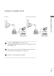
If connected to AV IN1 input, select AV1 input source. 3 Operate the corresponding external equipment. 25 EXTERNAL EQUIPMENT SETUP OTHER A/V SOURCE SETUP 32 inches 42/47/50/52/60 inches USB IN USB IN VIDEO L/MONO AUDIO R 1 AV IN 2 VIDEO L/MONO AUDIO R S-VIDEO 1 AV IN 2 VIDEO L R Camcorder Video Game Set VIDEO L R Camcorder Video Game Set 1 Connect the AUDIO/VIDEO jacks between TV and external equipment. Match the jack colours.(Video = yellow, Audio Left = white, and Audio Right = red) 2 Select AV2 input source using the INPUT button on the remote control.
If connected to AV IN1 input, select AV1 input source. 3 Operate the corresponding external equipment. 25 EXTERNAL EQUIPMENT SETUP OTHER A/V SOURCE SETUP 32 inches 42/47/50/52/60 inches USB IN USB IN VIDEO L/MONO AUDIO R 1 AV IN 2 VIDEO L/MONO AUDIO R S-VIDEO 1 AV IN 2 VIDEO L R Camcorder Video Game Set VIDEO L R Camcorder Video Game Set 1 Connect the AUDIO/VIDEO jacks between TV and external equipment. Match the jack colours.(Video = yellow, Audio Left = white, and Audio Right = red) 2 Select AV2 input source using the INPUT button on the remote control.
Owners Manual
Page 28
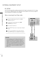
... the screen scanning rate for this purpose. NOTE G Check the image on the PC and the set . RGB OUTPUT AUDIO 26 VIDEO 3AUDIOTurn on your TV. If noise is present, change the PC output to another rate or adjust the brightness and contrast on the VIDEO menu until the picture is... PC graphic card can not be noise associated with the resolution, vertical pattern, contrast or brightness in input option of the PC graphic card. The TV perceives 1024x768, 60Hz as DTV 720p based on the PC graphic card. RGB IN RGB (PC) AUDIO (RGB/DVI) COMPONENT IN ANTEN IN REMOTE CONTROL...
... the screen scanning rate for this purpose. NOTE G Check the image on the PC and the set . RGB OUTPUT AUDIO 26 VIDEO 3AUDIOTurn on your TV. If noise is present, change the PC output to another rate or adjust the brightness and contrast on the VIDEO menu until the picture is... PC graphic card can not be noise associated with the resolution, vertical pattern, contrast or brightness in input option of the PC graphic card. The TV perceives 1024x768, 60Hz as DTV 720p based on the PC graphic card. RGB IN RGB (PC) AUDIO (RGB/DVI) COMPONENT IN ANTEN IN REMOTE CONTROL...
Owners Manual
Page 33
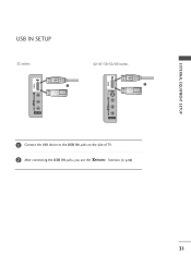
EXTERNAL EQUIPMENT SETUP USB IN SETUP 32 inches 42/47/50/52/60 inches USB IN USB IN 1 S-VIDEO 1 S-VIDEO VIDEO LV/IMDOENOO LA/UMDOINOO RAUDIO R VIDEO LV/IMDOENOO LA/UMDOINOO RAUDIO RUSB IN USB IN AV IN 2 AV IN 2 AV IN 2 AV IN 2 i 1 Connect the USB device to the USB IN jacks on the side of TV. 2 After connecting the USB IN jacks, you use the function. (G p.54) 31
EXTERNAL EQUIPMENT SETUP USB IN SETUP 32 inches 42/47/50/52/60 inches USB IN USB IN 1 S-VIDEO 1 S-VIDEO VIDEO LV/IMDOENOO LA/UMDOINOO RAUDIO R VIDEO LV/IMDOENOO LA/UMDOINOO RAUDIO RUSB IN USB IN AV IN 2 AV IN 2 AV IN 2 AV IN 2 i 1 Connect the USB device to the USB IN jacks on the side of TV. 2 After connecting the USB IN jacks, you use the function. (G p.54) 31

Owners Manual
Page 34
... Operating Manual of the second TV or monitor for AV out. VIDEO AUDIO REMOTE ONTROL IN DIGITAL AUDIO OUT OPTICAL VIDEO RS-232C IN TROL & SERVICE) AUDIO IDEO VIDEO (MONO) AUDIO ! AV IN 1 AV OUT HDMI/DVI IN RGB IN RGB (PC) 1 Connect the second TV or monitor to hook up... a second TV or monitor. EXTERNAL EQUIPMENT SETUP EXTERNAL EQUIPMENT SETUP AV OUTPUT SETUP The TV has a special signal output capability which allows you to the TV's AV OUT jacks. NOTE G Only Digital, Analogue mode can be used...
... Operating Manual of the second TV or monitor for AV out. VIDEO AUDIO REMOTE ONTROL IN DIGITAL AUDIO OUT OPTICAL VIDEO RS-232C IN TROL & SERVICE) AUDIO IDEO VIDEO (MONO) AUDIO ! AV IN 1 AV OUT HDMI/DVI IN RGB IN RGB (PC) 1 Connect the second TV or monitor to hook up... a second TV or monitor. EXTERNAL EQUIPMENT SETUP EXTERNAL EQUIPMENT SETUP AV OUTPUT SETUP The TV has a special signal output capability which allows you to the TV's AV OUT jacks. NOTE G Only Digital, Analogue mode can be used...
Owners Manual
Page 35
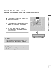
...) 1 AUDIO S-VIDEO VIDEO (MONO) AUDIO 2 ! tal audio (optical) input on the audio equipment. 1 (DVI) VIDEO AUDIO 3 Set the "TV Speaker option - NOTE G When connecting with external audio equipments, such as amplifiers or speakers, please turn the TV speakers off. AV OUT EXTERNAL EQUIPMENT SETUP AV IN 1 DIGITAL AUDIO OUTPUT SETUP Send the...
...) 1 AUDIO S-VIDEO VIDEO (MONO) AUDIO 2 ! tal audio (optical) input on the audio equipment. 1 (DVI) VIDEO AUDIO 3 Set the "TV Speaker option - NOTE G When connecting with external audio equipments, such as amplifiers or speakers, please turn the TV speakers off. AV OUT EXTERNAL EQUIPMENT SETUP AV IN 1 DIGITAL AUDIO OUTPUT SETUP Send the...


