Owners Manual
Page 3
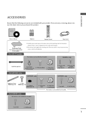
... Cord Polishing Cloth This feature is not available for stand assembly Refer to p. 9 50PY3DF* only Additional Cover Refer to p. 16 2 - TV Brackets, Bolts 2- Wall Brackets 1 INPUT D/A INPUT POWER SIMPLINK BRIGHT MODE TV VCR DVD RATIO TEXT INFO i GUIDE Owner's Manual 1.5V 1.5V Batteries MENU EXIT SUBTITLE MARK OK VOL Q.VIEW PR PAGE...
... Cord Polishing Cloth This feature is not available for stand assembly Refer to p. 9 50PY3DF* only Additional Cover Refer to p. 16 2 - TV Brackets, Bolts 2- Wall Brackets 1 INPUT D/A INPUT POWER SIMPLINK BRIGHT MODE TV VCR DVD RATIO TEXT INFO i GUIDE Owner's Manual 1.5V 1.5V Batteries MENU EXIT SUBTITLE MARK OK VOL Q.VIEW PR PAGE...
Owners Manual
Page 4
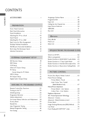
... Model Info 39 Auto Programme Tuning 40 Manual Programme Tuning 42 Fine Tuning 44 Assigning a Station Name 45 Programme Edit 46 Input List 48 Calling Up the Channel List 49 Input Source Selection 50 SIMPLINK 51 Key Lock 53 Entry Modes 54 Photo List 55 Music List 59 EPG(ELECTRONIC PROGRAMME GUIDE...
... Model Info 39 Auto Programme Tuning 40 Manual Programme Tuning 42 Fine Tuning 44 Assigning a Station Name 45 Programme Edit 46 Input List 48 Calling Up the Channel List 49 Input Source Selection 50 SIMPLINK 51 Key Lock 53 Entry Modes 54 Photo List 55 Music List 59 EPG(ELECTRONIC PROGRAMME GUIDE...

Owners Manual
Page 5
... 88 Sleep Timer Setting 89 Auto Shut-off Setting 90 PARENTAL CONTROL / RATINGS Set Password & Lock System 91 Programme Blocking 93 Parental Guidance 94 External Input Blocking 95 APPENDIX Troubleshooting 98 Maintenance 100 Product Specifications 101 Programming the Remote Control 104 IR Codes 107 External Control through RS-232C 109 Open...
... 88 Sleep Timer Setting 89 Auto Shut-off Setting 90 PARENTAL CONTROL / RATINGS Set Password & Lock System 91 Programme Blocking 93 Parental Guidance 94 External Input Blocking 95 APPENDIX Troubleshooting 98 Maintenance 100 Product Specifications 101 Programming the Remote Control 104 IR Codes 107 External Control through RS-232C 109 Open...

Owners Manual
Page 6
INPUT Button POWER Button OK Button VOLUME MENU Button (F,G) Buttons PROGRAMME (E,D) Buttons 4 PREPARATION FRONT PANEL CONTROLS I If your TV. I This is switched on. Image shown may ... your product has a protection film attached, remove the film and then wipe the product with a polishing cloth. 50/60PY3DF* PREPARATION Remote Control Sensor Program Display INPUT MENU OK Touch Pad VOL OK PR PR Power Standby Indicator • illuminates red in standby mode. • illuminates white when the set is a simplified...
INPUT Button POWER Button OK Button VOLUME MENU Button (F,G) Buttons PROGRAMME (E,D) Buttons 4 PREPARATION FRONT PANEL CONTROLS I If your TV. I This is switched on. Image shown may ... your product has a protection film attached, remove the film and then wipe the product with a polishing cloth. 50/60PY3DF* PREPARATION Remote Control Sensor Program Display INPUT MENU OK Touch Pad VOL OK PR PR Power Standby Indicator • illuminates red in standby mode. • illuminates white when the set is a simplified...

Owners Manual
Page 7
...; illuminates red in standby mode. • illuminates green when the set is switched on . INPUT MENU OK VOL PR INPUT MENU OK VOL PR POWER Button INPUT Button MENU Button OK Button VOLUME Buttons PROGRAMME Buttons 42/47/52LB9DF*, 32LB9D* VOL PR CH PROGRAMME (E,D) ButtonsCH VOL VOLUME (F,G) Buttons VOL OK Button MENU Button OK...
...; illuminates red in standby mode. • illuminates green when the set is switched on . INPUT MENU OK VOL PR INPUT MENU OK VOL PR POWER Button INPUT Button MENU Button OK Button VOLUME Buttons PROGRAMME Buttons 42/47/52LB9DF*, 32LB9D* VOL PR CH PROGRAMME (E,D) ButtonsCH VOL VOLUME (F,G) Buttons VOL OK Button MENU Button OK...
Owners Manual
Page 9
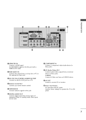
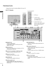
... ConRnS-2e32cCtINa second TV or monitor. (CONTROL & SERVICE) Connect your wired remote control. 10 Power Cord Socket 5 ANTENNA IN Connect antenna signals to the appropriate input port. Connect a component video/audio device to these jacks. 8 AV (Audio/Video) IN 1 2 RGB/AUDIO IN Connect audio/video output from an external Connect the...
... ConRnS-2e32cCtINa second TV or monitor. (CONTROL & SERVICE) Connect your wired remote control. 10 Power Cord Socket 5 ANTENNA IN Connect antenna signals to the appropriate input port. Connect a component video/audio device to these jacks. 8 AV (Audio/Video) IN 1 2 RGB/AUDIO IN Connect audio/video output from an external Connect the...
Owners Manual
Page 10
... Control Port Connect a second TV or monitor. VIDEO L/MONO AUDIO R VIDEO L/MONO AUDIO R USB IN VIDEO L/MONO AUDIO R VIDEO L/MONO AUDIO R AUDIO/VIDEO Input Connect audio/video output AV IN 2 AV INAV2IN 2 AV IN 2 from an external device to these jacks. 8 AV (Audio/Video) IN 1 2 RGB/AUDIO ...Connect your TV. RGB IN RGB (PC) IN Caution: (RAGUBD/DIOVIp) ower. LCD TV Models 42/47/52LB9DF* USB IN S-VIDEO USB IN 32LB9D* USB IN S-VIDEO USB Input S-VIDEO Input Connect S-Video out from your wired remote control. 10 Power Cord Socket 5 ANTENNA IN HDMI/DVI IN Connect ...
... Control Port Connect a second TV or monitor. VIDEO L/MONO AUDIO R VIDEO L/MONO AUDIO R USB IN VIDEO L/MONO AUDIO R VIDEO L/MONO AUDIO R AUDIO/VIDEO Input Connect audio/video output AV IN 2 AV INAV2IN 2 AV IN 2 from an external device to these jacks. 8 AV (Audio/Video) IN 1 2 RGB/AUDIO ...Connect your TV. RGB IN RGB (PC) IN Caution: (RAGUBD/DIOVIp) ower. LCD TV Models 42/47/52LB9DF* USB IN S-VIDEO USB IN 32LB9D* USB IN S-VIDEO USB Input S-VIDEO Input Connect S-Video out from your wired remote control. 10 Power Cord Socket 5 ANTENNA IN HDMI/DVI IN Connect ...

Owners Manual
Page 20
...EXTERNAL EQUIPMENT SETUP I This part of EXTERNAL EQUIPMENT SETUP mainly use pictures for the digital set-top box.) 4 Select Component 1 input source using the INPUT button on the set. I To prevent the equipment damage, never plug in any power cords until you have finished connecting all ...a Component cables RGB IN RGB (PC) 1 Connect the video outputs (Y, PB, PR) of the digital set top box to COMPONENT IN 2 input, select Component 2 input source. COMPONENT IN VIDEO AUDIO 1 2 Signal 480i 480p 576i 576p 720p 1080i 1080p Component 1/2 Yes Yes Yes Yes Yes Yes Yes HDMI/DVI 1,...
...EXTERNAL EQUIPMENT SETUP I This part of EXTERNAL EQUIPMENT SETUP mainly use pictures for the digital set-top box.) 4 Select Component 1 input source using the INPUT button on the set. I To prevent the equipment damage, never plug in any power cords until you have finished connecting all ...a Component cables RGB IN RGB (PC) 1 Connect the video outputs (Y, PB, PR) of the digital set top box to COMPONENT IN 2 input, select Component 2 input source. COMPONENT IN VIDEO AUDIO 1 2 Signal 480i 480p 576i 576p 720p 1080i 1080p Component 1/2 Yes Yes Yes Yes Yes Yes Yes HDMI/DVI 1,...

Owners Manual
Page 21
... of the source device to the owner's manual for the digital set-top box.) 1 COMPONENT IN VIDEO AUDIO 4 Select HDMI1, HDMI2 or HDMI3 input source using the INPUT button on the set. G If the digital set-top box player does not support Auto HDMI, you need to 1280x720p. EXTERNAL EQUIPMENT SETUP AUDIO...
... of the source device to the owner's manual for the digital set-top box.) 1 COMPONENT IN VIDEO AUDIO 4 Select HDMI1, HDMI2 or HDMI3 input source using the INPUT button on the set. G If the digital set-top box player does not support Auto HDMI, you need to 1280x720p. EXTERNAL EQUIPMENT SETUP AUDIO...
Owners Manual
Page 22
... the set. 3 Turn on the digital set-top box. (Refer to the owner's manual for the digital set-top box.) 4 Select HDMI1, HDMI2 or HDMI3 input source with using the INPUT button on the remote control. 20
... the set. 3 Turn on the digital set-top box. (Refer to the owner's manual for the digital set-top box.) 4 Select HDMI1, HDMI2 or HDMI3 input source with using the INPUT button on the remote control. 20
Owners Manual
Page 23
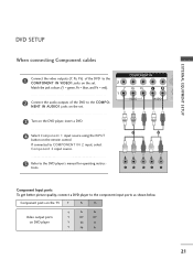
...shown below. EXTERNAL EQUIPMENT SETUP RGB IN RGB (PC) COMPONENT IN DIGI AUDIO (C VIDEO AUDIO S 1 2 Y PB PR L R Component Input ports To get better picture quality, connect a DVD player to the COMPO- Component ports on the TV Y PB PR Video output ports on the...IN VIDEO1 jacks on the set . 3 Turn on the DVD player, insert a DVD. 4 Select Component 1 input source using the INPUT button on the remote control. If connected to COMPONENT IN 2 input, select Component 2 input source. 5 Refer to the DVD player's manual for operating instruc- NENT IN AUDIO1 jacks on DVD player Y...
...shown below. EXTERNAL EQUIPMENT SETUP RGB IN RGB (PC) COMPONENT IN DIGI AUDIO (C VIDEO AUDIO S 1 2 Y PB PR L R Component Input ports To get better picture quality, connect a DVD player to the COMPO- Component ports on the TV Y PB PR Video output ports on the...IN VIDEO1 jacks on the set . 3 Turn on the DVD player, insert a DVD. 4 Select Component 1 input source using the INPUT button on the remote control. If connected to COMPONENT IN 2 input, select Component 2 input source. 5 Refer to the DVD player's manual for operating instruc- NENT IN AUDIO1 jacks on DVD player Y...

Owners Manual
Page 24
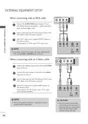
... or 3 jack on the set. 2 No separate audio connection is necessary. 3 Select HDMI1, HDMI2 or HDMI3 input source using the INPUT button on the set . If connected to AV IN 2 input, select A V 2 input source.(Except 32LB9D*) 5 Refer to 1280x720p. UO S-VIDEO VIDEO (MONO) AUDIO 1 2 When connecting HDMI cable...Connect the HDMI output of the DVD to the S-VIDEO input on the set . 3 Turn on the DVD player, insert a DVD. 4 Select A V 1 input source using the INPUT button on the remote control. 4 Refer to the AUDIO input jacks on the remote control. VIDEO AUDIO 2 Connect the ...
... or 3 jack on the set. 2 No separate audio connection is necessary. 3 Select HDMI1, HDMI2 or HDMI3 input source using the INPUT button on the set . If connected to AV IN 2 input, select A V 2 input source.(Except 32LB9D*) 5 Refer to 1280x720p. UO S-VIDEO VIDEO (MONO) AUDIO 1 2 When connecting HDMI cable...Connect the HDMI output of the DVD to the S-VIDEO input on the set . 3 Turn on the DVD player, insert a DVD. 4 Select A V 1 input source using the INPUT button on the remote control. 4 Refer to the AUDIO input jacks on the remote control. VIDEO AUDIO 2 Connect the ...
Owners Manual
Page 26
... G The picture quality is improved: ; S-VIDEO VIDEO L R ANT IN OUTPUT ANT OUT SWITCH CAUTION G Do not connect to AV IN 2 input, select A V 2 input source.(Except 32LB9D*) 1 (DVI) VIDEO AUDIO ! If connected to both Video and the S-Video cables, only the S-Video will work. 24 If...) AUDIO AV IN 1 EXTERNAL EQUIPMENT SETUP 2 Insert a video tape into the VCR and preAsUDsDIGIPOITLAOALUYTon the VCR. (Refer to AV IN2, select A V 2 input source. ! VIDEO L R S-VIDEO DIGITAL AUDIO OUT ANT IN OUTPUT ANT OUT SWITCH AV IN 1 AUDIO S-VIDEO VIDEO (MONO) AUDIO 2 Connect the audio...
... G The picture quality is improved: ; S-VIDEO VIDEO L R ANT IN OUTPUT ANT OUT SWITCH CAUTION G Do not connect to AV IN 2 input, select A V 2 input source.(Except 32LB9D*) 1 (DVI) VIDEO AUDIO ! If connected to both Video and the S-Video cables, only the S-Video will work. 24 If...) AUDIO AV IN 1 EXTERNAL EQUIPMENT SETUP 2 Insert a video tape into the VCR and preAsUDsDIGIPOITLAOALUYTon the VCR. (Refer to AV IN2, select A V 2 input source. ! VIDEO L R S-VIDEO DIGITAL AUDIO OUT ANT IN OUTPUT ANT OUT SWITCH AV IN 1 AUDIO S-VIDEO VIDEO (MONO) AUDIO 2 Connect the audio...
Owners Manual
Page 27
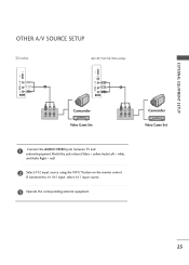
If connected to AV IN1 input, select AV1 input source. 3 Operate the corresponding external equipment. 25 Match the jack colours.(Video = yellow, Audio Left = white, and Audio Right = red) 2 Select AV2 input source using the INPUT button on the remote control. EXTERNAL EQUIPMENT SETUP OTHER A/V SOURCE SETUP 32 inches 42/47/50/52/60 inches USB IN USB IN VIDEO L/MONO AUDIO R 1 AV IN 2 VIDEO L/MONO AUDIO R S-VIDEO 1 AV IN 2 VIDEO L R Camcorder Video Game Set VIDEO L R Camcorder Video Game Set 1 Connect the AUDIO/VIDEO jacks between TV and external equipment.
If connected to AV IN1 input, select AV1 input source. 3 Operate the corresponding external equipment. 25 Match the jack colours.(Video = yellow, Audio Left = white, and Audio Right = red) 2 Select AV2 input source using the INPUT button on the remote control. EXTERNAL EQUIPMENT SETUP OTHER A/V SOURCE SETUP 32 inches 42/47/50/52/60 inches USB IN USB IN VIDEO L/MONO AUDIO R 1 AV IN 2 VIDEO L/MONO AUDIO R S-VIDEO 1 AV IN 2 VIDEO L R Camcorder Video Game Set VIDEO L R Camcorder Video Game Set 1 Connect the AUDIO/VIDEO jacks between TV and external equipment.
Owners Manual
Page 28
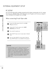
...232C IN (CONTROL & SERVICE) VIDEO AUDIO S-VIDEO VIDEO (MON 1 2 ! There may be changed, change the PC graphic card or consult the manufacturer of Special menu, INPUT button is clear. If necessary, change the screen scanning rate for this purpose. RGB OUTPUT AUDIO 26 If noise is present, change the PC output... on the PC graphic card. If the refresh rate of the PC to the AUDIO (RGB/DVI) jack on the set . 4 Select RGB-PC input source in input option of Special menu. 5 Once you select RGB-PC in PC mode. When connecting D-sub 15pin cable RGB IN 1 AUDIO (RGB/DVI) Connect ...
...232C IN (CONTROL & SERVICE) VIDEO AUDIO S-VIDEO VIDEO (MON 1 2 ! There may be changed, change the PC graphic card or consult the manufacturer of Special menu, INPUT button is clear. If necessary, change the screen scanning rate for this purpose. RGB OUTPUT AUDIO 26 If noise is present, change the PC output... on the PC graphic card. If the refresh rate of the PC to the AUDIO (RGB/DVI) jack on the set . 4 Select RGB-PC input source in input option of Special menu. 5 Once you select RGB-PC in PC mode. When connecting D-sub 15pin cable RGB IN 1 AUDIO (RGB/DVI) Connect ...
Owners Manual
Page 29
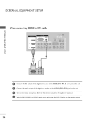
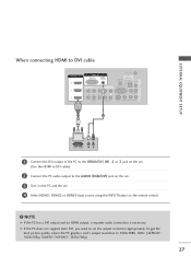
.... (42PB4D* : 1024x768p, 32LB9D*/50PB4D*: 1360x768p) 27 G If the PC does not support Auto DVI, you need to set . 4 Select HDMI1, HDMI2 or HDMI3 input source using the INPUT button on the PC and the set the output resolution appropriately. AV OUT EXTERNAL EQUIPMENT SETUP When connecting HDMI to DVI cable HDMI/DVI...
.... (42PB4D* : 1024x768p, 32LB9D*/50PB4D*: 1360x768p) 27 G If the PC does not support Auto DVI, you need to set . 4 Select HDMI1, HDMI2 or HDMI3 input source using the INPUT button on the PC and the set the output resolution appropriately. AV OUT EXTERNAL EQUIPMENT SETUP When connecting HDMI to DVI cable HDMI/DVI...

Owners Manual
Page 30
The fixed image may not work if a HDMI to DVI Cable is separate. G The synchronization input form for a long period of time. G Avoid keeping a fixed image on the screen. NOTES G Depending on the graphics card, DOS mode may become permanently imprinted ...
The fixed image may not work if a HDMI to DVI Cable is separate. G The synchronization input form for a long period of time. G Avoid keeping a fixed image on the screen. NOTES G Depending on the graphics card, DOS mode may become permanently imprinted ...

Owners Manual
Page 31
EXTERNAL EQUIPMENT SETUP Screen Setup for PC mode Overview When the RGB input, of the set is connected to enter the screen adjustment menu. When you to the screen adjustment menu. 29 Picture Mode Colour Temperature XD Advanced ... : 16:9 Picture Mode Colour Temperature XD Advanced Aspect Ratio Picture Reset Screen G Selection ( G or ) leads you change the resolution, select the proper resolution in present input to see the best picture appearance. 1 Press the MENU button and then use D or E button to select the PICTURE menu. 2 Press the G button and then...
EXTERNAL EQUIPMENT SETUP Screen Setup for PC mode Overview When the RGB input, of the set is connected to enter the screen adjustment menu. When you to the screen adjustment menu. 29 Picture Mode Colour Temperature XD Advanced ... : 16:9 Picture Mode Colour Temperature XD Advanced Aspect Ratio Picture Reset Screen G Selection ( G or ) leads you change the resolution, select the proper resolution in present input to see the best picture appearance. 1 Press the MENU button and then use D or E button to select the PICTURE menu. 2 Press the G button and then...

Owners Manual
Page 34
... for VCR recording. 1 VIDEO L R S-VIDEO 32 COMPONENT IN 2 2 See the Operating Manual of the second TV or monitor for fur1th(DeVrI) details regarding that device's input settings. EXTERNAL EQUIPMENT SETUP EXTERNAL EQUIPMENT SETUP AV OUTPUT SETUP The TV has a special signal output capability which allows you to the TV's AV OUT...
... for VCR recording. 1 VIDEO L R S-VIDEO 32 COMPONENT IN 2 2 See the Operating Manual of the second TV or monitor for fur1th(DeVrI) details regarding that device's input settings. EXTERNAL EQUIPMENT SETUP EXTERNAL EQUIPMENT SETUP AV OUTPUT SETUP The TV has a special signal output capability which allows you to the TV's AV OUT...
Owners Manual
Page 35
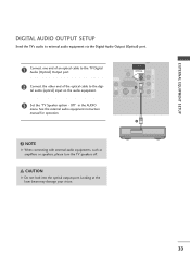
... TRGVB (DPCi)gital Audio (Optical) Output port. RGB IN HDMI/DVI IN 1 Connect one end of the optical cable to the digi- tal audio (optical) input on the audio equipment. 1 (DVI) VIDEO AUDIO 3 Set the "TV Speaker option - NOTE G When connecting with external audio equipments, such as amplifiers or speakers, please...
... TRGVB (DPCi)gital Audio (Optical) Output port. RGB IN HDMI/DVI IN 1 Connect one end of the optical cable to the digi- tal audio (optical) input on the audio equipment. 1 (DVI) VIDEO AUDIO 3 Set the "TV Speaker option - NOTE G When connecting with external audio equipments, such as amplifiers or speakers, please...


