
Owners Manual
Page 1
LCD TV MODELS 32LB9D* 42LB9DF* 47LB9DF* 52LB9DF* PLASMA TV MODELS 50PY3DF* 60PY3DF* 42PB4D* 50PB4D* DVB is a registered trademark of the DVB Project ID Number: 4757: 32LB9D 4756: 42LB9DF 4755: 47LB9DF 4754: 52LB9DF 4709: 50PY3DF 4708: 60PY3DF 4836: 42PB4D 4837: 50PB4D O N L Y :42LB9DF 47LB9DF 52LB9DF 50PY3DF 60PY3DF
LCD TV MODELS 32LB9D* 42LB9DF* 47LB9DF* 52LB9DF* PLASMA TV MODELS 50PY3DF* 60PY3DF* 42PB4D* 50PB4D* DVB is a registered trademark of the DVB Project ID Number: 4757: 32LB9D 4756: 42LB9DF 4755: 47LB9DF 4754: 52LB9DF 4709: 50PY3DF 4708: 60PY3DF 4836: 42PB4D 4837: 50PB4D O N L Y :42LB9DF 47LB9DF 52LB9DF 50PY3DF 60PY3DF
Owners Manual
Page 3
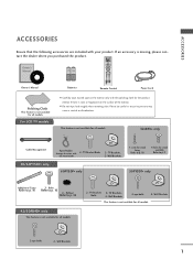
... or discoloration. Wall Brackets This feature is not available for all models. 2-eye-bolts 2- INPUT D/A INPUT POWER SIMPLINK BRIGHT MODE TV VCR DVD RATIO TEXT INFO i GUIDE Owner's Manual 1.5V 1.5V Batteries MENU EXIT SUBTITLE MARK OK VOL Q.VIEW PR PAGE MUTE 1... 2 3 4 5 6 7 8 9 LIST 0 FAV SIZE ? TV Bracket Bolts the twist holder. 2- Rubber Refer to p. 16 3 - TV Brackets, Bolts 2- TV Brackets, 2- TV Bracket 2- Wall Brackets 1 If an accessory is not available for all models. 32LB9D* only Cable Management...
... or discoloration. Wall Brackets This feature is not available for all models. 2-eye-bolts 2- INPUT D/A INPUT POWER SIMPLINK BRIGHT MODE TV VCR DVD RATIO TEXT INFO i GUIDE Owner's Manual 1.5V 1.5V Batteries MENU EXIT SUBTITLE MARK OK VOL Q.VIEW PR PAGE MUTE 1... 2 3 4 5 6 7 8 9 LIST 0 FAV SIZE ? TV Bracket Bolts the twist holder. 2- Rubber Refer to p. 16 3 - TV Brackets, Bolts 2- TV Brackets, 2- TV Bracket 2- Wall Brackets 1 If an accessory is not available for all models. 32LB9D* only Cable Management...
Owners Manual
Page 4
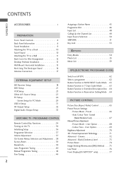
... 71 Advanced - CONTENTS CONTENTS ACCESSORIES 1 PREPARATION i Front Panel Controls 4 Back Panel Information 6 Stand Installation 9 Attaching the TV to a Desk 10 Swivel Stand 10 Attaching the TV to a Wall 11 Back Cover for PC Mode 29 USB In Setup 31 AV Output Setup 32 Digital Audio Output Setup... 33 WATCHING TV / PROGRAMME CONTROL Remote Control Key Functions 34 Turning on the TV 36 Initializing Setup 36 Programme Selection 37 Volume Adjustment 37 On-Screen Menus Selection and Adjustment . ...
... 71 Advanced - CONTENTS CONTENTS ACCESSORIES 1 PREPARATION i Front Panel Controls 4 Back Panel Information 6 Stand Installation 9 Attaching the TV to a Desk 10 Swivel Stand 10 Attaching the TV to a Wall 11 Back Cover for PC Mode 29 USB In Setup 31 AV Output Setup 32 Digital Audio Output Setup... 33 WATCHING TV / PROGRAMME CONTROL Remote Control Key Functions 34 Turning on the TV 36 Initializing Setup 36 Programme Selection 37 Volume Adjustment 37 On-Screen Menus Selection and Adjustment . ...

Owners Manual
Page 5
CONTENTS SOUND & LANGUAGE CONTROL Auto Volume Leveler ( Auto Volume 78 Preset Sound Settings- Sound Mode 79 Sound Setting Adjustment - User Mode 80 Balance 82 TV Speakers On/ Off Setup 83 I/II - Stereo/Dual Reception 84 - Speaker Sound Output Selection 84 Subtitle 85 TIME SETTING Clock Setting 86 Auto On/ Off ...
CONTENTS SOUND & LANGUAGE CONTROL Auto Volume Leveler ( Auto Volume 78 Preset Sound Settings- Sound Mode 79 Sound Setting Adjustment - User Mode 80 Balance 82 TV Speakers On/ Off Setup 83 I/II - Stereo/Dual Reception 84 - Speaker Sound Output Selection 84 Subtitle 85 TIME SETTING Clock Setting 86 Auto On/ Off ...

Owners Manual
Page 6
... the front panel. I This is switched on. INPUT Button POWER Button OK Button VOLUME MENU Button (F,G) Buttons PROGRAMME (E,D) Buttons 4 PREPARATION FRONT PANEL CONTROLS I If your TV.
... the front panel. I This is switched on. INPUT Button POWER Button OK Button VOLUME MENU Button (F,G) Buttons PROGRAMME (E,D) Buttons 4 PREPARATION FRONT PANEL CONTROLS I If your TV.
Owners Manual
Page 9
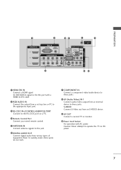
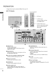
... signal to the this jack. RGB IN HDMI/DVI IN 3 RS-232C IN (CONTROL &SERVICE)RPGBO(PRC)T AUDIO (RGB/DVI) Connect to operate the TV on a PC. AUDIO S-VIDEO VIDEO ( ) AUDIO 6 DIGITAL AUDIO OUT Connect digital audio from an S-VIDEO device. device to the appropriate input port. ...-232C port on DC power. AUDIO OUT REMOTE CONTROL IN OPTICAL VIDEO 9 AV OUT AV OUT 4 Remote Control Port COMPONENT IN ConRnS-2e32cCtINa second TV or monitor. (CONTROL & SERVICE) Connect your wired remote control. 10 Power Cord Socket 5 ANTENNA IN Connect antenna signals to DVI cable. S-VIDEO...
... signal to the this jack. RGB IN HDMI/DVI IN 3 RS-232C IN (CONTROL &SERVICE)RPGBO(PRC)T AUDIO (RGB/DVI) Connect to operate the TV on a PC. AUDIO S-VIDEO VIDEO ( ) AUDIO 6 DIGITAL AUDIO OUT Connect digital audio from an S-VIDEO device. device to the appropriate input port. ...-232C port on DC power. AUDIO OUT REMOTE CONTROL IN OPTICAL VIDEO 9 AV OUT AV OUT 4 Remote Control Port COMPONENT IN ConRnS-2e32cCtINa second TV or monitor. (CONTROL & SERVICE) Connect your wired remote control. 10 Power Cord Socket 5 ANTENNA IN Connect antenna signals to DVI cable. S-VIDEO...
Owners Manual
Page 10
...of COMPONENT IN equipment. Never attemDIGpITtALto AUDIO OUT operate the TV on a PC. 9 AV OUT 4 Remote Control Port Connect a second TV or monitor. RS-232C IN (CONTROL & SERVICE) AV IN 1 8 VIDEO AUDIO S-VIDEO VIDEO ( ) AUDIO LCD TV Models 42/47/52LB9DF* USB IN S-VIDEO USB IN 32LB9D* USB IN ... SERVICE) AUDIO VIDEO AUDIO S-VIDEO VIDEO (MONO) AUDIO AV IN 1 7 89 1 HDMI/DVI IN 7 COMPONENT IN Connect a HDMI signal. Connect your TV. RGB IN RGB (PC) IN Caution: (RAGUBD/DIOVIp) ower. Connect to the RS-232C port on DC REMOTE CONTROL IN OPTICAL VIDEO AV OUT 6 ...
...of COMPONENT IN equipment. Never attemDIGpITtALto AUDIO OUT operate the TV on a PC. 9 AV OUT 4 Remote Control Port Connect a second TV or monitor. RS-232C IN (CONTROL & SERVICE) AV IN 1 8 VIDEO AUDIO S-VIDEO VIDEO ( ) AUDIO LCD TV Models 42/47/52LB9DF* USB IN S-VIDEO USB IN 32LB9D* USB IN ... SERVICE) AUDIO VIDEO AUDIO S-VIDEO VIDEO (MONO) AUDIO AV IN 1 7 89 1 HDMI/DVI IN 7 COMPONENT IN Connect a HDMI signal. Connect your TV. RGB IN RGB (PC) IN Caution: (RAGUBD/DIOVIp) ower. Connect to the RS-232C port on DC REMOTE CONTROL IN OPTICAL VIDEO AV OUT 6 ...
Owners Manual
Page 12
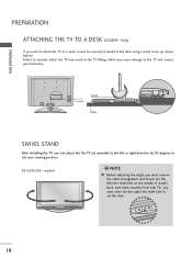
... securely fastened to the desk using a metal screw (as shown below). PREPARATION PREPARATION ATTACHING THE TV TO A DESK (32LB9D* Only) If you wish to attach the TV to a desk, it must be level with TV, you must remove the cable management and loosen (to the left or right direction by 20...your viewing position. 50/60PY3DF* models NOTE G Before adjusting the angle, you can adjust the the TV set the hole. 10 Failure to securely attach the TV may result in the TV falling: which may cause damage to the TV and serious personal injury. 1-screw Stand Desk SWIVEL STAND After installing the...
... securely fastened to the desk using a metal screw (as shown below). PREPARATION PREPARATION ATTACHING THE TV TO A DESK (32LB9D* Only) If you wish to attach the TV to a desk, it must be level with TV, you must remove the cable management and loosen (to the left or right direction by 20...your viewing position. 50/60PY3DF* models NOTE G Before adjusting the angle, you can adjust the the TV set the hole. 10 Failure to securely attach the TV may result in the TV falling: which may cause damage to the TV and serious personal injury. 1-screw Stand Desk SWIVEL STAND After installing the...

Owners Manual
Page 13
... so the product doesn't fall . It will prevent the product from the product. 60PY3DF* 1 50PY3DF* 1 2 42/50PB4D* 1 2 42/47/52LB9DF*, 32LB9D* 1 2 2 1 Use the eye-bolts or TV brackets/bolts to fix the product to the wall as parts of the bracket that children don't climb on the wall. 3 3 Use...If your product has the bolts in the eye-bolts position before inserting the eye-bolts, loosen the bolts.) * Insert the eye-bolts or TV brackets/bolts and tighten them securely in the forward direction. Please make sure that is pushed backwards. It is not available for all models....
... so the product doesn't fall . It will prevent the product from the product. 60PY3DF* 1 50PY3DF* 1 2 42/50PB4D* 1 2 42/47/52LB9DF*, 32LB9D* 1 2 2 1 Use the eye-bolts or TV brackets/bolts to fix the product to the wall as parts of the bracket that children don't climb on the wall. 3 3 Use...If your product has the bolts in the eye-bolts position before inserting the eye-bolts, loosen the bolts.) * Insert the eye-bolts or TV brackets/bolts and tighten them securely in the forward direction. Please make sure that is pushed backwards. It is not available for all models....
Owners Manual
Page 14
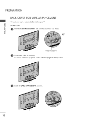
To connect additional equipment, see the External equipment Setup section. 3 Install the CABLE MANAGEMENT as necessary. PREPARATION PREPARATION BACK COVER FOR WIRE ARRANGEMENT I Here shown may be somewhat different from your TV. 50/60PY3DF* 1 Hold the CABLE MANAGEMENT with both hands and pull it as shown. 45° CABLE MANAGEMENT 2 Connect the cables as shown. 12
To connect additional equipment, see the External equipment Setup section. 3 Install the CABLE MANAGEMENT as necessary. PREPARATION PREPARATION BACK COVER FOR WIRE ARRANGEMENT I Here shown may be somewhat different from your TV. 50/60PY3DF* 1 Hold the CABLE MANAGEMENT with both hands and pull it as shown. 45° CABLE MANAGEMENT 2 Connect the cables as shown. 12
Owners Manual
Page 19
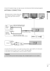
... plug in a poor signal area, please purchase a signal amplifier and install properly. For optimum picture quality, adjust antenna direction if needed. NOTE G The TV will let you have finished connecting all equipment. VIDEO L/MONO AUDIO R USB AV IN 2 S-VIDEO AV IN 2 S-VIDEO VIDEO L/MONO AUDIO R USB...) R AUDIO L/MONO VIDEO AV IN 1 AV OUT RF Coaxial Wire (75 ohm) Single-family Dwellings /Houses (Connect to be split for two TV's, install a 2-Way Signal Splitter. I If the antenna is not installed properly, contact your dealer for outdoor antenna) ANTENNA IN Antenna UHF Signal VHF...
... plug in a poor signal area, please purchase a signal amplifier and install properly. For optimum picture quality, adjust antenna direction if needed. NOTE G The TV will let you have finished connecting all equipment. VIDEO L/MONO AUDIO R USB AV IN 2 S-VIDEO AV IN 2 S-VIDEO VIDEO L/MONO AUDIO R USB...) R AUDIO L/MONO VIDEO AV IN 1 AV OUT RF Coaxial Wire (75 ohm) Single-family Dwellings /Houses (Connect to be split for two TV's, install a 2-Way Signal Splitter. I If the antenna is not installed properly, contact your dealer for outdoor antenna) ANTENNA IN Antenna UHF Signal VHF...

Owners Manual
Page 20
... set -top box.) 4 Select Component 1 input source using the INPUT button on the digital set-top box. (Refer to the owner's manual for the LCD TV models.
... set -top box.) 4 Select Component 1 input source using the INPUT button on the digital set-top box. (Refer to the owner's manual for the LCD TV models.
Owners Manual
Page 23
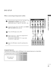
... Input ports To get better picture quality, connect a DVD player to the COMPO- tions. NENT IN AUDIO1 jacks on the set . Component ports on the TV Y PB PR Video output ports on the remote control. Match the jack colours (Y = green, PB = blue, and PR = red). 2 Connect the audio outputs of the...
... Input ports To get better picture quality, connect a DVD player to the COMPO- tions. NENT IN AUDIO1 jacks on the set . Component ports on the TV Y PB PR Video output ports on the remote control. Match the jack colours (Y = green, PB = blue, and PR = red). 2 Connect the audio outputs of the...
Owners Manual
Page 25
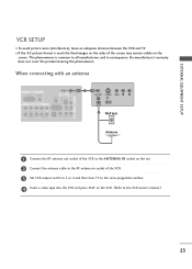
... OUTPUT SWITCH 2 Wall Jack 1 (DVI) VI Antenna 1 Connect the RF antenna out socket of the VCR. 3 Set VCR output switch to 3 or 4 and then tune TV to the same programme number. 4 Insert a video tape into the VCR and press PLAY on the screen. 2 1 (DVI) COMPONENT IN VIDEO AUDIO VIDEO ( ) AUDIO AV... I If the 4:3 picture format is common to the VCR owner's manual.) 23 I To avoid picture noise (interference), leave an adequate distance between the VCR and TV. This phenomenon is used;
... OUTPUT SWITCH 2 Wall Jack 1 (DVI) VI Antenna 1 Connect the RF antenna out socket of the VCR. 3 Set VCR output switch to 3 or 4 and then tune TV to the same programme number. 4 Insert a video tape into the VCR and press PLAY on the screen. 2 1 (DVI) COMPONENT IN VIDEO AUDIO VIDEO ( ) AUDIO AV... I If the 4:3 picture format is common to the VCR owner's manual.) 23 I To avoid picture noise (interference), leave an adequate distance between the VCR and TV. This phenomenon is used;
Owners Manual
Page 26
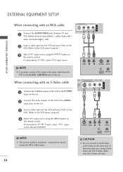
... using the INPUT button on 2 the remote control. COMPONENT IN 2 When connecting with an RCA cable 1 (DVI) VIDEO AUDIO 1 Connect the AUDIO/VIDEO jacks between TV and VCR. S-VIDEO VIDEO L R ANT IN OUTPUT ANT OUT SWITCH CAUTION G Do not connect to the AUDIO input jacks on the set . Match the jack...
... using the INPUT button on 2 the remote control. COMPONENT IN 2 When connecting with an RCA cable 1 (DVI) VIDEO AUDIO 1 Connect the AUDIO/VIDEO jacks between TV and VCR. S-VIDEO VIDEO L R ANT IN OUTPUT ANT OUT SWITCH CAUTION G Do not connect to the AUDIO input jacks on the set . Match the jack...
Owners Manual
Page 27
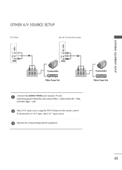
If connected to AV IN1 input, select AV1 input source. 3 Operate the corresponding external equipment. 25 EXTERNAL EQUIPMENT SETUP OTHER A/V SOURCE SETUP 32 inches 42/47/50/52/60 inches USB IN USB IN VIDEO L/MONO AUDIO R 1 AV IN 2 VIDEO L/MONO AUDIO R S-VIDEO 1 AV IN 2 VIDEO L R Camcorder Video Game Set VIDEO L R Camcorder Video Game Set 1 Connect the AUDIO/VIDEO jacks between TV and external equipment. Match the jack colours.(Video = yellow, Audio Left = white, and Audio Right = red) 2 Select AV2 input source using the INPUT button on the remote control.
If connected to AV IN1 input, select AV1 input source. 3 Operate the corresponding external equipment. 25 EXTERNAL EQUIPMENT SETUP OTHER A/V SOURCE SETUP 32 inches 42/47/50/52/60 inches USB IN USB IN VIDEO L/MONO AUDIO R 1 AV IN 2 VIDEO L/MONO AUDIO R S-VIDEO 1 AV IN 2 VIDEO L R Camcorder Video Game Set VIDEO L R Camcorder Video Game Set 1 Connect the AUDIO/VIDEO jacks between TV and external equipment. Match the jack colours.(Video = yellow, Audio Left = white, and Audio Right = red) 2 Select AV2 input source using the INPUT button on the remote control.
Owners Manual
Page 28
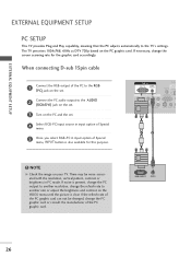
...for the graphic card accordingly. RGB OUTPUT AUDIO 26 There may be changed, change the refresh rate to the TV's settings. EXTERNAL EQUIPMENT SETUP EXTERNAL EQUIPMENT SETUP PC SETUP This TV provides Plug and Play capability, meaning that the PC adjusts automatically to another rate or adjust the brightness and...set . COMPONENT IN 2 Connect the PC audio output to the RGB AUDIO OUT (PC) jack on the set. The TV perceives 1024x768, 60Hz as DTV 720p based on your TV. NOTE G Check the image on the PC graphic card. If noise is present, change the PC output to another resolution...
...for the graphic card accordingly. RGB OUTPUT AUDIO 26 There may be changed, change the refresh rate to the TV's settings. EXTERNAL EQUIPMENT SETUP EXTERNAL EQUIPMENT SETUP PC SETUP This TV provides Plug and Play capability, meaning that the PC adjusts automatically to another rate or adjust the brightness and...set . COMPONENT IN 2 Connect the PC audio output to the RGB AUDIO OUT (PC) jack on the set. The TV perceives 1024x768, 60Hz as DTV 720p based on your TV. NOTE G Check the image on the PC graphic card. If noise is present, change the PC output to another resolution...
Owners Manual
Page 33
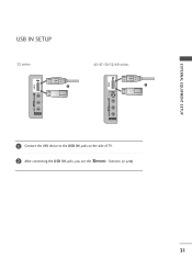
EXTERNAL EQUIPMENT SETUP USB IN SETUP 32 inches 42/47/50/52/60 inches USB IN USB IN 1 S-VIDEO 1 S-VIDEO VIDEO LV/IMDOENOO LA/UMDOINOO RAUDIO R VIDEO LV/IMDOENOO LA/UMDOINOO RAUDIO RUSB IN USB IN AV IN 2 AV IN 2 AV IN 2 AV IN 2 i 1 Connect the USB device to the USB IN jacks on the side of TV. 2 After connecting the USB IN jacks, you use the function. (G p.54) 31
EXTERNAL EQUIPMENT SETUP USB IN SETUP 32 inches 42/47/50/52/60 inches USB IN USB IN 1 S-VIDEO 1 S-VIDEO VIDEO LV/IMDOENOO LA/UMDOINOO RAUDIO R VIDEO LV/IMDOENOO LA/UMDOINOO RAUDIO RUSB IN USB IN AV IN 2 AV IN 2 AV IN 2 AV IN 2 i 1 Connect the USB device to the USB IN jacks on the side of TV. 2 After connecting the USB IN jacks, you use the function. (G p.54) 31

Owners Manual
Page 34
... Analogue mode can be used for fur1th(DeVrI) details regarding that device's input settings. COMPONENT IN 2 2 See the Operating Manual of the second TV or monitor for AV out. VIDEO AUDIO REMOTE ONTROL IN DIGITAL AUDIO OUT OPTICAL VIDEO RS-232C IN TROL & SERVICE) AUDIO IDEO VIDEO (MONO...) AUDIO ! G We recommend to the TV's AV OUT jacks. EXTERNAL EQUIPMENT SETUP EXTERNAL EQUIPMENT SETUP AV OUTPUT SETUP The TV has a special signal output capability which allows you to hook up a second...
... Analogue mode can be used for fur1th(DeVrI) details regarding that device's input settings. COMPONENT IN 2 2 See the Operating Manual of the second TV or monitor for AV out. VIDEO AUDIO REMOTE ONTROL IN DIGITAL AUDIO OUT OPTICAL VIDEO RS-232C IN TROL & SERVICE) AUDIO IDEO VIDEO (MONO...) AUDIO ! G We recommend to the TV's AV OUT jacks. EXTERNAL EQUIPMENT SETUP EXTERNAL EQUIPMENT SETUP AV OUTPUT SETUP The TV has a special signal output capability which allows you to hook up a second...
Owners Manual
Page 35
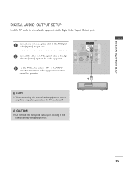
... & SERVICE) 1 AUDIO S-VIDEO VIDEO (MONO) AUDIO 2 ! NOTE G When connecting with external audio equipments, such as amplifiers or speakers, please turn the TV speakers off. CAUTION G Do not look into the optical output port. AV OUT EXTERNAL EQUIPMENT SETUP AV IN 1 DIGITAL AUDIO OUTPUT SETUP Send the... Looking at the laser beam may damage your vision. 33 tal audio (optical) input on the audio equipment. 1 (DVI) VIDEO AUDIO 3 Set the "TV Speaker option - Off" in the AUDIO menu. COMPONENT IN 2 2 Connect the other end of an optical cable to the TRGVB (DPCi)gital Audio (Optical...
... & SERVICE) 1 AUDIO S-VIDEO VIDEO (MONO) AUDIO 2 ! NOTE G When connecting with external audio equipments, such as amplifiers or speakers, please turn the TV speakers off. CAUTION G Do not look into the optical output port. AV OUT EXTERNAL EQUIPMENT SETUP AV IN 1 DIGITAL AUDIO OUTPUT SETUP Send the... Looking at the laser beam may damage your vision. 33 tal audio (optical) input on the audio equipment. 1 (DVI) VIDEO AUDIO 3 Set the "TV Speaker option - Off" in the AUDIO menu. COMPONENT IN 2 2 Connect the other end of an optical cable to the TRGVB (DPCi)gital Audio (Optical...


