

Owners Manual
Page 1
See the label attached on the back cover and relate this information to your TV. Retain this manual for future reference. Record model number and serial number of the TV in the spaces provided below. Model Number : Serial Number : Internet Home Page : http://www.lg.ca PLASMA TV OWNER'S MANUAL MODELS: 50PX4D/50PX5D 50PX4D-UB/50PX5D-UB R TruSurround XT TM Please read this manual carefully and completely before operating your dealer if you require service.
See the label attached on the back cover and relate this information to your TV. Retain this manual for future reference. Record model number and serial number of the TV in the spaces provided below. Model Number : Serial Number : Internet Home Page : http://www.lg.ca PLASMA TV OWNER'S MANUAL MODELS: 50PX4D/50PX5D 50PX4D-UB/50PX5D-UB R TruSurround XT TM Please read this manual carefully and completely before operating your dealer if you require service.
Owners Manual
Page 3
... is manufactured under license by direct connection to view encrypted digital programming. Digital Cable Compatibility This digital television is a trademark of the CableCARDTM TradeMark. Owner's Manual 3
... is manufactured under license by direct connection to view encrypted digital programming. Digital Cable Compatibility This digital television is a trademark of the CableCARDTM TradeMark. Owner's Manual 3
Owners Manual
Page 5
... wall outlets, loose or damaged wall outlets, extension cords, frayed power cords, or damaged or cracked wire insulation are dangerous. Unplug this owner's manual to be placed upon . Do not overload wall outlets. To Reduce The Risk Of Fire Or Electric Shock, Do Not Expose This Appliance To Rain... Or Moisture. 17. Owner's Manual 5 Servicing is damaged, liquid has been spilled or objects have the cord replaced with liquids, such as vases, shall be exposed to rain or ...
... wall outlets, loose or damaged wall outlets, extension cords, frayed power cords, or damaged or cracked wire insulation are dangerous. Unplug this owner's manual to be placed upon . Do not overload wall outlets. To Reduce The Risk Of Fire Or Electric Shock, Do Not Expose This Appliance To Rain... Or Moisture. 17. Owner's Manual 5 Servicing is damaged, liquid has been spilled or objects have the cord replaced with liquids, such as vases, shall be exposed to rain or ...
Owners Manual
Page 6
...60 TV Setup On-screen Menus Language Selection 61 Setup Menu Options EZ Scan (Channel Search 62 Manual Scan 62 Channel Edit 63 DTV Signal Strength 63 Channel Label Setup 64 Main Picture Source Selection 64...Control 65 Video Reset 65 Audio Menu Options Audio Language 66 EZ SoundRite / EZ Sound 66 Manual Sound Control (Custom Option 66 Front Surround 67 TV Speakers On/Off Setup 67 BBE 68 ...Stereo/SAP Broadcasts Setup 68 Time Menu Options Auto Clock Setup 69 Manual Clock Setup 69 On/Off Timer Setup 69 Sleep Timer / Auto Off 70 Option Menu Features Aspect...
...60 TV Setup On-screen Menus Language Selection 61 Setup Menu Options EZ Scan (Channel Search 62 Manual Scan 62 Channel Edit 63 DTV Signal Strength 63 Channel Label Setup 64 Main Picture Source Selection 64...Control 65 Video Reset 65 Audio Menu Options Audio Language 66 EZ SoundRite / EZ Sound 66 Manual Sound Control (Custom Option 66 Front Surround 67 TV Speakers On/Off Setup 67 BBE 68 ...Stereo/SAP Broadcasts Setup 68 Time Menu Options Auto Clock Setup 69 Manual Clock Setup 69 On/Off Timer Setup 69 Sleep Timer / Auto Off 70 Option Menu Features Aspect...

Owners Manual
Page 7
... PDP to viewers anywhere in -Picture feature allows you get the rich, dynamic colors that this product. Thus a few cell defects will not fit. Owner's Manual 7 This means that is as a descendant of fluorescent lamps. The Picture-in the room who can see the screen. A few cell defects are comprised of...
... PDP to viewers anywhere in -Picture feature allows you get the rich, dynamic colors that this product. Thus a few cell defects will not fit. Owner's Manual 7 This means that is as a descendant of fluorescent lamps. The Picture-in the room who can see the screen. A few cell defects are comprised of...
Owners Manual
Page 9
...™ Interface/Component2) received from an S-VIDEO device to HDMI1/DVI. Connect a HDMI sig- The voltage is available to these ports will not work. Owner's Manual 9 DVD/DTV Input G-LINKTM Connect an IR controller to this RS-232C INPUT (CONTROL/SERVICE) PORT Connect to the RS-232C port on a PC. (Component...
...™ Interface/Component2) received from an S-VIDEO device to HDMI1/DVI. Connect a HDMI sig- The voltage is available to these ports will not work. Owner's Manual 9 DVD/DTV Input G-LINKTM Connect an IR controller to this RS-232C INPUT (CONTROL/SERVICE) PORT Connect to the RS-232C port on a PC. (Component...
Owners Manual
Page 11
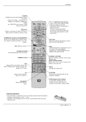
...VCR • mode button. But not available in Component 1-2, RGB, HDMI1/DVI and HDMI2 mode.(Refer to the last TV. with new ones. Owner's Manual 11 ࠘ POWER POWER ࠘ ࠘࠘ Installation POWER POWER ࠘ ࠘ POWER POWER TV INPUT •...-PC), HDMI1/DVI, HDMI2 and IEEE1394 input sources, screen returns to p.89) VOL CH FLASHBK CHANNEL UP/DOWN Selects available channels found during Manual scan. Brings up the menu to p.83, 85) • Controls the DVHS or Camcorder in Analog mode. VOL NUMBER buttons SAP Selects ...
...VCR • mode button. But not available in Component 1-2, RGB, HDMI1/DVI and HDMI2 mode.(Refer to the last TV. with new ones. Owner's Manual 11 ࠘ POWER POWER ࠘ ࠘࠘ Installation POWER POWER ࠘ ࠘ POWER POWER TV INPUT •...-PC), HDMI1/DVI, HDMI2 and IEEE1394 input sources, screen returns to p.89) VOL CH FLASHBK CHANNEL UP/DOWN Selects available channels found during Manual scan. Brings up the menu to p.83, 85) • Controls the DVHS or Camcorder in Analog mode. VOL NUMBER buttons SAP Selects ...
Owners Manual
Page 12
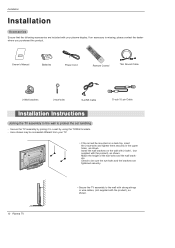
... them securely in the upper holes as shown. Check to be mounted on the wall with 2 bolts*, (not supplied with the product), as shown. Owner's Manual 1.5V 1.5V Batteries Power Cord FLASHBK APM M/C EJECT AUTO DEMO CC Remote Control 75Ω Round Cable 2-Wall brackets 2-eye-bolts G-LINK Cable D-sub 15...
... them securely in the upper holes as shown. Check to be mounted on the wall with 2 bolts*, (not supplied with the product), as shown. Owner's Manual 1.5V 1.5V Batteries Power Cord FLASHBK APM M/C EJECT AUTO DEMO CC Remote Control 75Ω Round Cable 2-Wall brackets 2-eye-bolts G-LINK Cable D-sub 15...
Owners Manual
Page 13
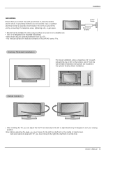
Owner's Manual 13 Do not try to ground the unit by 20 degrees to suit your TV. - Detailed installation ... you connect the earth ground wire to prevent possible electric shock. Here shown may be mounted horizontally. - This manual explains the features available on the 50PX4D series TVs. GROUNDING Ensure that you must close (to the right) the shaft bolt to... set manually to the left ) the shaft bolt on the middle of 4" on each side and the top, 2.36" on a...
Owner's Manual 13 Do not try to ground the unit by 20 degrees to suit your TV. - Detailed installation ... you connect the earth ground wire to prevent possible electric shock. Here shown may be mounted horizontally. - This manual explains the features available on the 50PX4D series TVs. GROUNDING Ensure that you must close (to the right) the shaft bolt to... set manually to the left ) the shaft bolt on the middle of 4" on each side and the top, 2.36" on a...
Owners Manual
Page 15
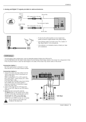
...remain on cable and antenna Antenna Bronze Wire RF Coaxial Wire (75 ohm) Installation Cable TV Wall Jack Turn clockwise to the VCR owner's manual.) 3. the fixed images on the sides of time. Connect the audio and video cables from VCR to the S-VIDEO input, the picture ...(MONO) A/V INPUT REMOTE CONTROL CABLE ANTENNA S-VIDEO AC INPUT 1 2 ANT OUT ANT IN S-VIDEO OUT OUTPUT SWITCH (R) AUDIO (L) 3 4 IN VIDEO VCR Rear Owner's Manual 15 Connection Option 1 Set VCR output switch to channel 3 or 4 and then tune the TV to VCR, match the PTICAL) RGB INPUT AUDIO INPUT jack...
...remain on cable and antenna Antenna Bronze Wire RF Coaxial Wire (75 ohm) Installation Cable TV Wall Jack Turn clockwise to the VCR owner's manual.) 3. the fixed images on the sides of time. Connect the audio and video cables from VCR to the S-VIDEO input, the picture ...(MONO) A/V INPUT REMOTE CONTROL CABLE ANTENNA S-VIDEO AC INPUT 1 2 ANT OUT ANT IN S-VIDEO OUT OUTPUT SWITCH (R) AUDIO (L) 3 4 IN VIDEO VCR Rear Owner's Manual 15 Connection Option 1 Set VCR output switch to channel 3 or 4 and then tune the TV to VCR, match the PTICAL) RGB INPUT AUDIO INPUT jack...
Owners Manual
Page 16
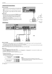
..., match the HDMI/DVI jack colors (Video = yellow, Audio Left = white, and Audio Right = red). Operate the corresponding external equipment. Refer to the DVD player's manual for Component 1 input source. • Digital Audio operation has priority if Digital Audio and AUDIO L/R are connected. 2. How to the AUDIO INPUT jacks on the...
..., match the HDMI/DVI jack colors (Video = yellow, Audio Left = white, and Audio Right = red). Operate the corresponding external equipment. Refer to the DVD player's manual for Component 1 input source. • Digital Audio operation has priority if Digital Audio and AUDIO L/R are connected. 2. How to the AUDIO INPUT jacks on the...
Owners Manual
Page 17
... the TV's COMPONENT (Y, PB, PR) INPUT, RGB, HDMI1/DVI or HDMI2 jack for video connections, depending on the remote control to the owner's manual for the digital set -top box. (Refer to select Component 1, Component 2, RGB-DTV, or HDMI1/DVI, HDMI2 source. This TV can be used...digital set -top box connector. Signal 480i 480p 720p 1080i Component 1/2 Yes Yes Yes Yes RGB-DTV,HDMI1/DVI,HDMI2 No Yes Yes Yes Owner's Manual 17 Installation IEEE-1394 HDMI 2 HDMI1 /DVI RS-232C INPUT (CONTROL/SERVICE) OUTPUT COMPONENT2 INPUT DVI INPUT DIGITAL AUDIO (OPTICAL) RGB IN HDSTB ...
... the TV's COMPONENT (Y, PB, PR) INPUT, RGB, HDMI1/DVI or HDMI2 jack for video connections, depending on the remote control to the owner's manual for the digital set -top box. (Refer to select Component 1, Component 2, RGB-DTV, or HDMI1/DVI, HDMI2 source. This TV can be used...digital set -top box connector. Signal 480i 480p 720p 1080i Component 1/2 Yes Yes Yes Yes RGB-DTV,HDMI1/DVI,HDMI2 No Yes Yes Yes Owner's Manual 17 Installation IEEE-1394 HDMI 2 HDMI1 /DVI RS-232C INPUT (CONTROL/SERVICE) OUTPUT COMPONENT2 INPUT DVI INPUT DIGITAL AUDIO (OPTICAL) RGB IN HDSTB ...
Owners Manual
Page 19
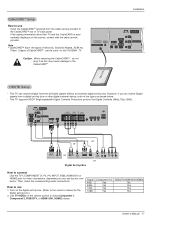
...(L) AUDIO (R) Digital Audio Output Send the TV's audio to hook up the second TV or monitor. See the external audio equipment instruction manual for Monitor out. • When connecting with external audio equipments, such as amplif- Installation Monitor Display Specifications (HDMI/DVI Mode) Resolution ...DVI RS-232C INPUT (CONTROL/SERVICE) OUTPUT COMPONENT2 DIGITAL AUDIO (OPTICAL) INPUT DVD /DTV RGB INPUT AUDIO INPUT INPU DVI INPUT Owner's Manual 19 Connect one end of the optical cable to p.67) Caution: Do not look into the optical output port. cal) input on the...
...(L) AUDIO (R) Digital Audio Output Send the TV's audio to hook up the second TV or monitor. See the external audio equipment instruction manual for Monitor out. • When connecting with external audio equipments, such as amplif- Installation Monitor Display Specifications (HDMI/DVI Mode) Resolution ...DVI RS-232C INPUT (CONTROL/SERVICE) OUTPUT COMPONENT2 DIGITAL AUDIO (OPTICAL) INPUT DVD /DTV RGB INPUT AUDIO INPUT INPU DVI INPUT Owner's Manual 19 Connect one end of the optical cable to p.67) Caution: Do not look into the optical output port. cal) input on the...
Owners Manual
Page 21
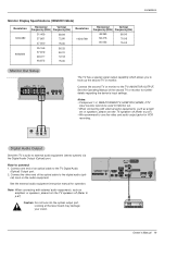
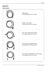
Reference Cable sample Installation HDMI Cable (not supplied with the product) HDMI to DVI Cable (not supplied with the product) Fiber Optic Digital Audio Cable (not supplied with the product) Analog Audio Cable(RCA type) (not supplied with the product) Analog Audio Cable(Stereo to RCA type) (not supplied with the product) Owner's Manual 21
Reference Cable sample Installation HDMI Cable (not supplied with the product) HDMI to DVI Cable (not supplied with the product) Fiber Optic Digital Audio Cable (not supplied with the product) Analog Audio Cable(RCA type) (not supplied with the product) Analog Audio Cable(Stereo to RCA type) (not supplied with the product) Owner's Manual 21
Owners Manual
Page 22
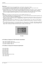
...1. Notes: - In case HDMI1/DVI Source Devices is not supported TV SET output in Main Input option on the SETUP menu.(Refer to the Manual of HDMI1/DVI Source Devices or contact your service center. - Select HDMI1/DVI Input source in HDMI1/DVI Source Devices, "INVALID FORMAT" OSD display...and contact an PC graphics card service center. - As shown the picture below, press the ADJUST button to Screen. Installation How to the Manual of HDMI1/DVI Source Devices or contact your service center. Use the Orbiter feature on the TV SET and HDMI1/DVI Source Devices remote ...
...1. Notes: - In case HDMI1/DVI Source Devices is not supported TV SET output in Main Input option on the SETUP menu.(Refer to the Manual of HDMI1/DVI Source Devices or contact your service center. - Select HDMI1/DVI Input source in HDMI1/DVI Source Devices, "INVALID FORMAT" OSD display...and contact an PC graphics card service center. - As shown the picture below, press the ADJUST button to Screen. Installation How to the Manual of HDMI1/DVI Source Devices or contact your service center. Use the Orbiter feature on the TV SET and HDMI1/DVI Source Devices remote ...
Owners Manual
Page 23
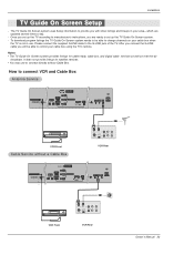
... AUDIO INPUT REMOTE CABLE CONTROL ANTENNA S-VIDEO AC INPUT VCR Front ANT OUT ANT IN OUT OUTPUT (R) AUDIO (L) SWITCH 3 4 IN S-VIDEO VIDEO VCR Rear Owner's Manual 23 After you connect the G-LINK cable you set up the TV according to set up the TV Guide On Screen system. - To download program...
... AUDIO INPUT REMOTE CABLE CONTROL ANTENNA S-VIDEO AC INPUT VCR Front ANT OUT ANT IN OUT OUTPUT (R) AUDIO (L) SWITCH 3 4 IN S-VIDEO VIDEO VCR Rear Owner's Manual 23 After you connect the G-LINK cable you set up the TV according to set up the TV Guide On Screen system. - To download program...
Owners Manual
Page 25
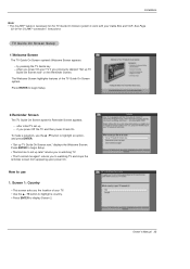
... the reminder screen from appearing upon power On. Press ENTER to begin Setup. 2.Reminder Screen The TV Guide On Screen system's Reminder Screen appears: -- Owner's Manual 25 by pressing the TV Guide key -- if you previously skipped "Set up -- How to highlight an option, and press ENTER. • "Set up later...
... the reminder screen from appearing upon power On. Press ENTER to begin Setup. 2.Reminder Screen The TV Guide On Screen system's Reminder Screen appears: -- Owner's Manual 25 by pressing the TV Guide key -- if you previously skipped "Set up -- How to highlight an option, and press ENTER. • "Set up later...

Owners Manual
Page 27
Make sure the G-LINKTM Cable is the cable box plugged into? • If you select Cable, you see Screen 6. • If you make any other choice, you see Screen 7 . 6. 5. Screen 5: Which TV input is properly installed. • Press ENTER to display Screen 8. Screen 6: Cable Box Tuning Channel • Select the channel used for the cable box. • Press ENTER to the cable box. Installation Owner's Manual 27 Screen 7: Cable Box Configuration Diagram • The diagram shows the correct way to install the G-LINK Cable from the back of the device to display Screen 7. 7.
Make sure the G-LINKTM Cable is the cable box plugged into? • If you select Cable, you see Screen 6. • If you make any other choice, you see Screen 7 . 6. 5. Screen 5: Which TV input is properly installed. • Press ENTER to display Screen 8. Screen 6: Cable Box Tuning Channel • Select the channel used for the cable box. • Press ENTER to the cable box. Installation Owner's Manual 27 Screen 7: Cable Box Configuration Diagram • The diagram shows the correct way to install the G-LINK Cable from the back of the device to display Screen 7. 7.
Owners Manual
Page 29
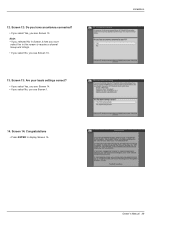
Screen 13: Are your basic settings correct? • If you select Yes, you see Screen 14. • If you select No, you see Screen 13. 13. Screen 14: Congratulations • Press ENTER to receive a channel lineup and listings. • If you select No, you see Screen 13. Installation Owner's Manual 29 12. Note: • If you selected No in this screen to display Screen 15. Screen 12: Do you have an antenna connected? • If you select Yes, you must select Yes in Screen 3 then you see Screen 1. 14.
Screen 13: Are your basic settings correct? • If you select Yes, you see Screen 14. • If you select No, you see Screen 13. 13. Screen 14: Congratulations • Press ENTER to receive a channel lineup and listings. • If you select No, you see Screen 13. Installation Owner's Manual 29 12. Note: • If you selected No in this screen to display Screen 15. Screen 12: Do you have an antenna connected? • If you select Yes, you must select Yes in Screen 3 then you see Screen 1. 14.
Owners Manual
Page 31
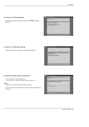
Notes : • Many VCRs require testing more than one code. • If you select No, a different code is tested again in Screen 19. Screen 20: VCR Tuned to display Screen 19. 19. Owner's Manual 31 Screen 19: VCR Code Testing • When testing is done, Screen 20 displays automatically. Screen 18: VCR Preparation • Follow the on-screen instructions, and press ENTER to Channel 9? • If you select Yes, you see Screen 21. • If you select Test this code again, the same code is tested in Screen 19. 18. Installation 20.
Notes : • Many VCRs require testing more than one code. • If you select No, a different code is tested again in Screen 19. Screen 20: VCR Tuned to display Screen 19. 19. Owner's Manual 31 Screen 19: VCR Code Testing • When testing is done, Screen 20 displays automatically. Screen 18: VCR Preparation • Follow the on-screen instructions, and press ENTER to Channel 9? • If you select Yes, you see Screen 21. • If you select Test this code again, the same code is tested in Screen 19. 18. Installation 20.


