

Owners Manual
Page 1
See the label attached on the back cover and relate this information to your TV. Model Number : Serial Number : Internet Home Page : http://www.lg.ca Record model number and serial number of the TV in the spaces provided below. PLASMA TV OWNER'S MANUAL MODELS: 50PX4D/50PX5D 50PX4D-UB/50PX5D-UB R TruSurround XT TM Please read this manual carefully and completely before operating your dealer if you require service. Retain this manual for future reference.
See the label attached on the back cover and relate this information to your TV. Model Number : Serial Number : Internet Home Page : http://www.lg.ca Record model number and serial number of the TV in the spaces provided below. PLASMA TV OWNER'S MANUAL MODELS: 50PX4D/50PX5D 50PX4D-UB/50PX5D-UB R TruSurround XT TM Please read this manual carefully and completely before operating your dealer if you require service. Retain this manual for future reference.
Owners Manual
Page 2
...to radio communications. WARNING/CAUTION TO REDUCE THE RISK OF FIRE AND ELECTRIC SHOCK, DO NOT EXPOSE THIS PRODUCT TO RAIN OR MOISTURE. 2 Plasma TV If this product. FCC NOTICE • A Class B digital device This equipment has been tested and found to comply with arrowhead symbol,...equipment generates, uses and can be of sufficient magnitude to correct the interference by turning the equipment off and on a circuit different from LG Electronics. Warning/Caution Warning/Caution WARNING/CAUTION RISK OF ELECTRIC SHOCK DO NOT OPEN WARNING/CAUTION: TO REDUCE THE RISK OF ELECTRIC SHOCK ...
...to radio communications. WARNING/CAUTION TO REDUCE THE RISK OF FIRE AND ELECTRIC SHOCK, DO NOT EXPOSE THIS PRODUCT TO RAIN OR MOISTURE. 2 Plasma TV If this product. FCC NOTICE • A Class B digital device This equipment has been tested and found to comply with arrowhead symbol,...equipment generates, uses and can be of sufficient magnitude to correct the interference by turning the equipment off and on a circuit different from LG Electronics. Warning/Caution Warning/Caution WARNING/CAUTION RISK OF ELECTRIC SHOCK DO NOT OPEN WARNING/CAUTION: TO REDUCE THE RISK OF ELECTRIC SHOCK ...
Owners Manual
Page 4
... follows. Protect the power cord from being walked on or pinched particularly at plugs, convenience receptacles, and the point where they exit from tip-over. 4 Plasma TV PORTABLE CART WARNING When a cart is intended to be verbatim as radiators, heat registers, stoves, or other . The following safety instruction list. This information...
... follows. Protect the power cord from being walked on or pinched particularly at plugs, convenience receptacles, and the point where they exit from tip-over. 4 Plasma TV PORTABLE CART WARNING When a cart is intended to be verbatim as radiators, heat registers, stoves, or other . The following safety instruction list. This information...
Owners Manual
Page 6
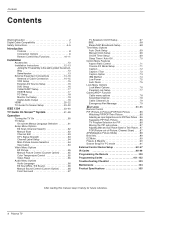
... the Remote 100 Programming Codes 101~102 Troubleshooting Checklist 103 Maintenance 104 Product Specifications 105 After reading this manual, keep it handy for future reference. 6 Plasma TV
... the Remote 100 Programming Codes 101~102 Troubleshooting Checklist 103 Maintenance 104 Product Specifications 105 After reading this manual, keep it handy for future reference. 6 Plasma TV

Owners Manual
Page 7
...-pixel is less than 5 inches thick. 160° - This means that you are in a display that are comprised of vision Your flat panel plasma screen offers an exceptionally broad viewing angle -- The PDP Manufacturing Process: a few minute colored dots may be viewed as a descendant of the neon lamp...the PDP manufacturing process. Thus a few cell defects will not fit. All of these cell defects during the manufacture and operation of the Plasma Display is so wide that you to install your PC and video images simultaneously. Wide Screen The screen of this PDP is clear and...
...-pixel is less than 5 inches thick. 160° - This means that you are in a display that are comprised of vision Your flat panel plasma screen offers an exceptionally broad viewing angle -- The PDP Manufacturing Process: a few minute colored dots may be viewed as a descendant of the neon lamp...the PDP manufacturing process. Thus a few cell defects will not fit. All of these cell defects during the manufacture and operation of the Plasma Display is so wide that you to install your PC and video images simultaneously. Wide Screen The screen of this PDP is clear and...
Owners Manual
Page 8
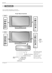
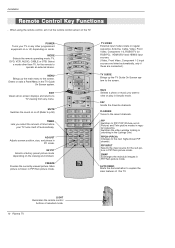
Introduction Controls - When the TV is turned on TV GUIDE or off. 8 Plasma TV TV GUIDE Remote Control Sensor CHANNEL (E, D) Buttons VOLUME (F,G) Buttons MENU Button TV/VIDEO Button Power Standby Indicator Illuminates orange in standby mode. This is seen. TV GUIDE Button POWER Button Here shown may be somewhat different from your TV. 50PX5D Front Panel Controls TV GUIDE 50PX4D INDEX Switches LED Display on , the indicator will blink green for 3-4 seconds before the picture is a simplified representation of a front panel. -
Introduction Controls - When the TV is turned on TV GUIDE or off. 8 Plasma TV TV GUIDE Remote Control Sensor CHANNEL (E, D) Buttons VOLUME (F,G) Buttons MENU Button TV/VIDEO Button Power Standby Indicator Illuminates orange in standby mode. This is seen. TV GUIDE Button POWER Button Here shown may be somewhat different from your TV. 50PX5D Front Panel Controls TV GUIDE 50PX4D INDEX Switches LED Display on , the indicator will blink green for 3-4 seconds before the picture is a simplified representation of a front panel. -
Owners Manual
Page 10
... equipment on or off .(Refer to p.90) TIMER Lets you want to the screen. PIP Switches to explain the main features of selected mode. 10 Plasma TV SWAP Exchanges the main/sub images in the TV Guide On Screen system. FREEZE Freezes the currently-viewed picture. PIP INPUT Selects the input...
... equipment on or off .(Refer to p.90) TIMER Lets you want to the screen. PIP Switches to explain the main features of selected mode. 10 Plasma TV SWAP Exchanges the main/sub images in the TV Guide On Screen system. FREEZE Freezes the currently-viewed picture. PIP INPUT Selects the input...
Owners Manual
Page 12
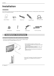
...*, (not supplied with your TV. • If the set tumbling - Here shown may be somewhat different from your plasma display. Installation Installation Accessories Ensure that the following accessories are tightened securely. 12 Plasma TV • Secure the TV assembly to the wall with strong strings or wire cables, (not supplied with the...
...*, (not supplied with your TV. • If the set tumbling - Here shown may be somewhat different from your plasma display. Installation Installation Accessories Ensure that the following accessories are tightened securely. 12 Plasma TV • Secure the TV assembly to the wall with strong strings or wire cables, (not supplied with the...
Owners Manual
Page 14
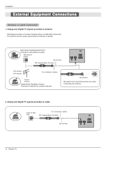
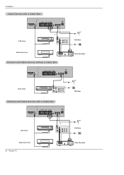
... connecting the antenna. 2. Wall Antenna Socket or Outdoor Antenna without a Cable Box Connection - RF Coaxial Wire (75 ohm) Bronze Wire CABLE ANTENNA AC INPUT 14 Plasma TV Installation External Equipment Connections Antenna or Cable Connection 1.
... connecting the antenna. 2. Wall Antenna Socket or Outdoor Antenna without a Cable Box Connection - RF Coaxial Wire (75 ohm) Bronze Wire CABLE ANTENNA AC INPUT 14 Plasma TV Installation External Equipment Connections Antenna or Cable Connection 1.
Owners Manual
Page 16
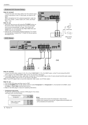
Note that RGB, HDMI1/DVI and HDMI2 sources are connected at the same time. 16 Plasma TV Connect the DVD video outputs (Y, PB, PR) to the COMPONENT (Y, PB, PR) INPUT jacks on the TV and connect the DVD audio outputs to ...
Note that RGB, HDMI1/DVI and HDMI2 sources are connected at the same time. 16 Plasma TV Connect the DVD video outputs (Y, PB, PR) to the COMPONENT (Y, PB, PR) INPUT jacks on the TV and connect the DVD audio outputs to ...
Owners Manual
Page 17
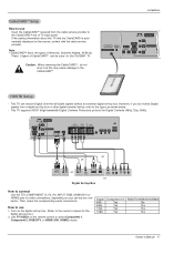
CableCARDTTMM Setup How to use 1. This TV can be used for this PLASMA TV. Cable IEEE-1394 HDMI 2 HDMI1 /DVI RS-232C INPUT (CONTROL/SERVICE) OUTPUT COMPONENT2 INPUT DVI INPUT DIGITAL AUDIO (OPTICAL) RGB INPUT AUDIO INPUT DVD /...
CableCARDTTMM Setup How to use 1. This TV can be used for this PLASMA TV. Cable IEEE-1394 HDMI 2 HDMI1 /DVI RS-232C INPUT (CONTROL/SERVICE) OUTPUT COMPONENT2 INPUT DVI INPUT DIGITAL AUDIO (OPTICAL) RGB INPUT AUDIO INPUT DVD /...
Owners Manual
Page 18
... 48.077 72.18 46.875 75.00 53.674 85.06 48.363 60.00 56.476 70.06 60.023 75.02 18 Plasma TV If the PC(or the sound card of RGB INPUT port. This TV provides Plug and Play capability, meaning that the PC adjusts automatically...
... 48.077 72.18 46.875 75.00 53.674 85.06 48.363 60.00 56.476 70.06 60.023 75.02 18 Plasma TV If the PC(or the sound card of RGB INPUT port. This TV provides Plug and Play capability, meaning that the PC adjusts automatically...
Owners Manual
Page 20
... - When you need to HDMI1/DVI or HDMI2 port of this TV with an HDMI cable(not supplied with this TV with this purpose. 20 Plasma TV How To Connect 1. Connect the source device to set the output resolution appropriately. Select HDMI1/DVI or HDMI2 input source in main input option...
... - When you need to HDMI1/DVI or HDMI2 port of this TV with an HDMI cable(not supplied with this TV with this purpose. 20 Plasma TV How To Connect 1. Connect the source device to set the output resolution appropriately. Select HDMI1/DVI or HDMI2 input source in main input option...
Owners Manual
Page 22
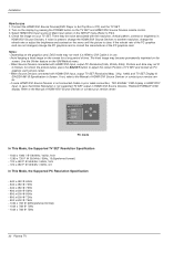
... @ 75Hz - 800 x 600 @ 56Hz - 800 x 600 @ 60Hz - 800 x 600 @ 72Hz - 800 x 600 @ 75Hz - 1024 x 768 @ 60Hz(preferred format) - 1024 x 768 @ 70Hz - 1024 x 768 @ 75Hz 22 Plasma TV In case HDMI1/DVI Source Devices is in use 1. Refer to P.64) 4. When Source Devices connected with the resolution, vertical pattern, contrast or brightness...
... @ 75Hz - 800 x 600 @ 56Hz - 800 x 600 @ 60Hz - 800 x 600 @ 72Hz - 800 x 600 @ 75Hz - 1024 x 768 @ 60Hz(preferred format) - 1024 x 768 @ 70Hz - 1024 x 768 @ 75Hz 22 Plasma TV In case HDMI1/DVI Source Devices is in use 1. Refer to P.64) 4. When Source Devices connected with the resolution, vertical pattern, contrast or brightness...
Owners Manual
Page 24
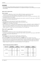
... CABLE ANTENNA S-VIDEO AC INPUT VCR Front or ANT OUT ANT IN OUT S-VIDEO OUTPUT (R) AUDIO (L) SWITCH 3 4 IN VIDEO VCR Rear Cable Box Front 24 Plasma TV RF Cable OUTPUT SWITCH 34 (R) AUDIO (L) VIDEO TV VCR Cable Box Rear
... CABLE ANTENNA S-VIDEO AC INPUT VCR Front or ANT OUT ANT IN OUT S-VIDEO OUTPUT (R) AUDIO (L) SWITCH 3 4 IN VIDEO VCR Rear Cable Box Front 24 Plasma TV RF Cable OUTPUT SWITCH 34 (R) AUDIO (L) VIDEO TV VCR Cable Box Rear
Owners Manual
Page 26
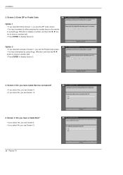
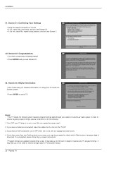
Screen 4: Do you have Cable Service connected? • If you select Yes, you see Screen 4. • If you select No, you see Screen 12. 26 Plasma TV Installation 2. Option 2 • If you selected Canada in Screen 1, you see the Postal Code screen. • You input characters by either pressing the number ...
Screen 4: Do you have Cable Service connected? • If you select Yes, you see Screen 4. • If you select No, you see Screen 12. 26 Plasma TV Installation 2. Option 2 • If you selected Canada in Screen 1, you see the Postal Code screen. • You input characters by either pressing the number ...
Owners Manual
Page 28
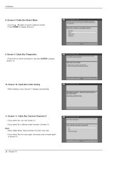
...; If you select Yes, you see Screen 12. • If you select Test this code again, the same code is tested in Screen 10. 28 Plasma TV Screen 10: Cable Box Code Testing • When testing is done, Screen 11 displays automatically. 11.
...; If you select Yes, you see Screen 12. • If you select Test this code again, the same code is tested in Screen 10. 28 Plasma TV Screen 10: Cable Box Code Testing • When testing is done, Screen 11 displays automatically. 11.
Owners Manual
Page 30
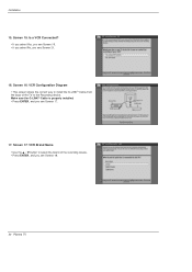
Screen 15: Is a VCR Connected? • If you select Yes, you see Screen 16. • If you select No, you see Screen 17. 17. Make sure the G-LINKTM Cable is properly installed. • Press ENTER, and you see Screen 18. 30 Plasma TV Screen 17: VCR Brand Name • Use the D / E button to select the brand of the TV to install the G-LINKTM Cable from the back of the recording device. • Press ENTER, and you see Screen 21. 16. Screen 16: VCR Configuration Diagram • This screen shows the correct way to the Recording device. Installation 15.
Screen 15: Is a VCR Connected? • If you select Yes, you see Screen 16. • If you select No, you see Screen 17. 17. Make sure the G-LINKTM Cable is properly installed. • Press ENTER, and you see Screen 18. 30 Plasma TV Screen 17: VCR Brand Name • Use the D / E button to select the brand of the TV to install the G-LINKTM Cable from the back of the recording device. • Press ENTER, and you see Screen 21. 16. Screen 16: VCR Configuration Diagram • This screen shows the correct way to the Recording device. Installation 15.
Owners Manual
Page 32
In order to receive regular program listings, please remember to receive all eight days of TV program listings. 32 Plasma TV If you have successfully completed Setup! • Press ENTER and you see Screen 23. 23. Notes: • The TV Guide On Screen system receives ...
In order to receive regular program listings, please remember to receive all eight days of TV program listings. 32 Plasma TV If you have successfully completed Setup! • Press ENTER and you see Screen 23. 23. Notes: • The TV Guide On Screen system receives ...
Owners Manual
Page 34
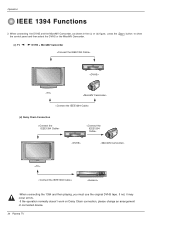
If not, it may occur errors. -If the operation normally doesn't work on Daisy Chain connection, please change an arrangement of connected device. 34 Plasma TV When connecting the DVHS and the MicroMV Camcorder, as shown in the (c) or (d) figure, press the 1394 button to show the control panel and then select the DVHS or the MicroMV Camcorder. (c) TV DVHS + MicroMV Camcorder (d) Daisy Chain Connection -When connecting the 1394 and then playing, you must use the original DVHS tape. Operation IEEE 1394 Functions 2.
If not, it may occur errors. -If the operation normally doesn't work on Daisy Chain connection, please change an arrangement of connected device. 34 Plasma TV When connecting the DVHS and the MicroMV Camcorder, as shown in the (c) or (d) figure, press the 1394 button to show the control panel and then select the DVHS or the MicroMV Camcorder. (c) TV DVHS + MicroMV Camcorder (d) Daisy Chain Connection -When connecting the 1394 and then playing, you must use the original DVHS tape. Operation IEEE 1394 Functions 2.


