
Owner's Manual
Page 6
Channel Editing 45 Channel List 46 Favorite Channel Setup 47 Favorite Channel List 47 Brief Information 48 Input List 49 Input Label 50 AV Mode 51 SIMPLINK 52 USB Entry Modes 54 Photo List 55 Music List 61 PICTURE CONTROL Picture Size (Aspect Ratio) Control 64 ...
Channel Editing 45 Channel List 46 Favorite Channel Setup 47 Favorite Channel List 47 Brief Information 48 Input List 49 Input Label 50 AV Mode 51 SIMPLINK 52 USB Entry Modes 54 Photo List 55 Music List 61 PICTURE CONTROL Picture Size (Aspect Ratio) Control 64 ...

Owner's Manual
Page 7
... Setting 92 Sleep Timer Setting 93 PARENTAL CONTROL / RATINGS Set Password & Lock System 94 Channel Blocking 97 Movie & TV Rating 98 Downloadable Rating 103 External Input Blocking 104 Key lock 105 APPENDIX Troubleshooting 106 Maintenance 108 Product Specifications 109 IR Codes 112 External Control Through RS-232C 114 7
... Setting 92 Sleep Timer Setting 93 PARENTAL CONTROL / RATINGS Set Password & Lock System 94 Channel Blocking 97 Movie & TV Rating 98 Downloadable Rating 103 External Input Blocking 104 Key lock 105 APPENDIX Troubleshooting 106 Maintenance 108 Product Specifications 109 IR Codes 112 External Control Through RS-232C 114 7
Owner's Manual
Page 9
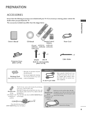
... ferrite core close to P.15) x 2 Cable Holder * Wipe spots on the display. ENERGY SAVING 1 AV MODE INPUT ON/OFF 42 TV 753 86 LIST 0 9 MENU VOL FAVMARK MUTERATIO CH INFO FLASHBK P A G E ENERGY SAVING 1 AV MODE INPUT 42 TV ENTER BACK EXIT FREEZE Q.MENU or 753 86 LIST 0 9 MENU VOL FAVMARK MUTERATIO CH...
... ferrite core close to P.15) x 2 Cable Holder * Wipe spots on the display. ENERGY SAVING 1 AV MODE INPUT ON/OFF 42 TV 753 86 LIST 0 9 MENU VOL FAVMARK MUTERATIO CH INFO FLASHBK P A G E ENERGY SAVING 1 AV MODE INPUT 42 TV ENTER BACK EXIT FREEZE Q.MENU or 753 86 LIST 0 9 MENU VOL FAVMARK MUTERATIO CH...
Owner's Manual
Page 10
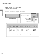
PREPARATION PREPARATION FRONT PANEL INFORMATION I Image shown may differ from your finger. 10 The LED is off while the TV remains on. Remote Control Sensor ENTER VOL CH POWER INPUT Button Button MENU Button ENTER Button VOLUME Buttons CHANNEL Buttons ENTER You can operate the button just by touching the button lightly with your TV. 50/60PK550, 50/60PK540, 42/50PJ550, 50/60PK550C Intelligent Sensor Adjusts picture according to the surrounding conditions. ENTER VOL CH Power/Standby Indicator Illuminates red in standby mode.
PREPARATION PREPARATION FRONT PANEL INFORMATION I Image shown may differ from your finger. 10 The LED is off while the TV remains on. Remote Control Sensor ENTER VOL CH POWER INPUT Button Button MENU Button ENTER Button VOLUME Buttons CHANNEL Buttons ENTER You can operate the button just by touching the button lightly with your TV. 50/60PK550, 50/60PK540, 42/50PJ550, 50/60PK550C Intelligent Sensor Adjusts picture according to the surrounding conditions. ENTER VOL CH Power/Standby Indicator Illuminates red in standby mode.

Owner's Manual
Page 11
The LED is off while the TV remains on. PREPARATION 50/60PK250, 42/50PJ250, 60PK280, 60PK290 Intelligent Sensor Adjusts picture according to the surrounding conditions. ENTER VOL CH Power/Standby Indicator Illuminates red in standby mode. Remote Control Sensor ENTER VOL CH POWER INPUT Button Button MENU Button ENTER Button VOLUME Buttons CHANNEL Buttons ENTER You can operate the button just by touching the button lightly with your finger. 11
The LED is off while the TV remains on. PREPARATION 50/60PK250, 42/50PJ250, 60PK280, 60PK290 Intelligent Sensor Adjusts picture according to the surrounding conditions. ENTER VOL CH Power/Standby Indicator Illuminates red in standby mode. Remote Control Sensor ENTER VOL CH POWER INPUT Button Button MENU Button ENTER Button VOLUME Buttons CHANNEL Buttons ENTER You can operate the button just by touching the button lightly with your finger. 11

Owner's Manual
Page 12
ENTER VOL CH Power/Standby Indicator Illuminates red in standby mode. G Do not step on . Remote Control Sensor ENTER VOL CH VOL POWER Button INPUT Button CH MENU Button ENTER Button VOLUME Buttons CHANNEL Buttons You can operate the button just by touching the button lightly with your finger. The ...
ENTER VOL CH Power/Standby Indicator Illuminates red in standby mode. G Do not step on . Remote Control Sensor ENTER VOL CH VOL POWER Button INPUT Button CH MENU Button ENTER Button VOLUME Buttons CHANNEL Buttons You can operate the button just by touching the button lightly with your finger. The ...
Owner's Manual
Page 13
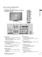
... IN PORT For a wired remote control. 6 COMPONENT IN Analog Connection. Uses a red, green, and blue cable for video & red and white for analog PC audio input. Doesn't support 480i. R VIDEO L/MONO AUDIO R HDMI IN 3 SERVICE ONLY R R PREPARATION BACK PANEL INFORMATION I Image shown may differ from your TV. 42/50PJ250, 50/60PK250...
... IN PORT For a wired remote control. 6 COMPONENT IN Analog Connection. Uses a red, green, and blue cable for video & red and white for analog PC audio input. Doesn't support 480i. R VIDEO L/MONO AUDIO R HDMI IN 3 SERVICE ONLY R R PREPARATION BACK PANEL INFORMATION I Image shown may differ from your TV. 42/50PJ250, 50/60PK250...

Owner's Manual
Page 14
.../DVI IN Digital Connection. Supports HD video and Digital audio. Uses a red, green, and blue cable for video & red and white for analog PC audio input.
.../DVI IN Digital Connection. Supports HD video and Digital audio. Uses a red, green, and blue cable for video & red and white for analog PC audio input.
Owner's Manual
Page 22
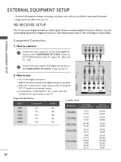
EXTERNAL EQUIPMENT SETUP Component Connection 1. How to use I If connected to COMPONENT IN 2 input, select the Component2 input source on the TV. 1 2 O IN /DVI) REMOTE CONTROL IN AV IN 1 VIDEO /MONO AUDIO 2 L R 1 VIDEO AUDIO COMPONENT IN ANT CA Supported Resolutions ..., refer to connect 1 Connect the video outputs (Y, PB, PR) of the digital set -top box. EXTERNAL EQUIPMENT SETUP I Select the Component1 input source on the TV using the INPUT button on the remote control. Match the jack colors (Y = green, PB = blue, and PR = red). However, if you have finished ...
EXTERNAL EQUIPMENT SETUP Component Connection 1. How to use I If connected to COMPONENT IN 2 input, select the Component2 input source on the TV. 1 2 O IN /DVI) REMOTE CONTROL IN AV IN 1 VIDEO /MONO AUDIO 2 L R 1 VIDEO AUDIO COMPONENT IN ANT CA Supported Resolutions ..., refer to connect 1 Connect the video outputs (Y, PB, PR) of the digital set -top box. EXTERNAL EQUIPMENT SETUP I Select the Component1 input source on the TV using the INPUT button on the remote control. Match the jack colors (Y = green, PB = blue, and PR = red). However, if you have finished ...
Owner's Manual
Page 23
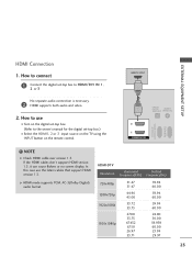
... HDMI cables don't support HDMI version 1.3, it can cause flickers or no screen display. In this case use I Select the HDMI1, 2 or 3 input source on the TV using the INPUT button on the digital set-top box. (Refer to the owner's manual for the digital set -top box to HDMI/DVI IN...
... HDMI cables don't support HDMI version 1.3, it can cause flickers or no screen display. In this case use I Select the HDMI1, 2 or 3 input source on the TV using the INPUT button on the digital set-top box. (Refer to the owner's manual for the digital set -top box to HDMI/DVI IN...
Owner's Manual
Page 24
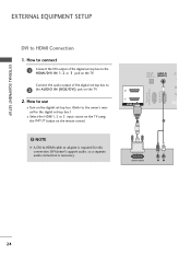
How to connect 1 Connect the DVI output of the digital set -top box.) I Select the HDMI1, 2 or 3 input source on the TV using the INPUT button on the remote control. ! NOTE G A DVI to HDMI cable or adapter is necessary. How to use I Turn on the digital set -top box to ...
How to connect 1 Connect the DVI output of the digital set -top box.) I Select the HDMI1, 2 or 3 input source on the TV using the INPUT button on the remote control. ! NOTE G A DVI to HDMI cable or adapter is necessary. How to use I Turn on the digital set -top box to ...
Owner's Manual
Page 25
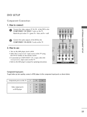
...ports Y on the remote control. Match the jack colors (Y = green, PB = blue, and PR = red). How to COMPONENT IN 2 input, select the Component2 input source on the DVD player, insert a DVD. EXTERNAL EQUIPMENT SETUP DVD SETUP Component Connection 1. Y PB PR L R 2 Connect the audio .../MONO AUDIO 2 L R 1 VIDEO AUDIO A COMPONENT IN Component Input ports To get better picture quality, connect a DVD player to the component input ports as shown below. I Select the Component1 input source on the TV using the INPUT button on DVD player Y Y PB PR PB PR B-Y R-Y Cb...
...ports Y on the remote control. Match the jack colors (Y = green, PB = blue, and PR = red). How to COMPONENT IN 2 input, select the Component2 input source on the DVD player, insert a DVD. EXTERNAL EQUIPMENT SETUP DVD SETUP Component Connection 1. Y PB PR L R 2 Connect the audio .../MONO AUDIO 2 L R 1 VIDEO AUDIO A COMPONENT IN Component Input ports To get better picture quality, connect a DVD player to the component input ports as shown below. I Select the Component1 input source on the TV using the INPUT button on DVD player Y Y PB PR PB PR B-Y R-Y Cb...

Owner's Manual
Page 26
EXTERNAL EQUIPMENT SETUP EXTERNAL EQUIPMENT SETUP HDMI Connection 1. HDMI-DVD OUTPUT 1 OPTICAL DIGITAL AUDIO OUT AUD (RGB/D 2 1 HDMI/DVI IN RS-232C IN (CONTROL & SERVICE) RGB IN (PC) 26 How to connect 1 Connect the HDMI output of the DVD to the DVD player's manual for operating instructions. HDMI supports both audio and video. 2. I Select the HDMI1, 2 or 3 input source on the TV using the INPUT button on the TV. 2 No separate audio connection is necessary. How to use I Refer to the HDMI/DVI IN 1, 2 or 3 jack on the remote control.
EXTERNAL EQUIPMENT SETUP EXTERNAL EQUIPMENT SETUP HDMI Connection 1. HDMI-DVD OUTPUT 1 OPTICAL DIGITAL AUDIO OUT AUD (RGB/D 2 1 HDMI/DVI IN RS-232C IN (CONTROL & SERVICE) RGB IN (PC) 26 How to connect 1 Connect the HDMI output of the DVD to the DVD player's manual for operating instructions. HDMI supports both audio and video. 2. I Select the HDMI1, 2 or 3 input source on the TV using the INPUT button on the TV. 2 No separate audio connection is necessary. How to use I Refer to the HDMI/DVI IN 1, 2 or 3 jack on the remote control.
Owner's Manual
Page 27
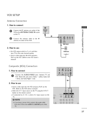
...jack colors (Video = yellow, Audio Left = white, and Audio Right = red) 2. ANTENNA/ CABLE IN 1 2 Connect the antenna cable to AV IN 2, select AV2 input source on the remote control. How to the VCR owner's manual.) ANT OUT S-VIDEO VIDEO L R ANT IN 2 OUTPUT SWITCH Wall Jack Antenna Composite (RCA) Connection... 1. How to use I Insert a video tape into the VCR and press PLAY on the VCR. (Refer to use I Select the A V 1 input source on the TV using the INPUT button on the TV. ! NOTE G If you have a mono VCR, connect the audio cable from the VCR to the same channel number...
...jack colors (Video = yellow, Audio Left = white, and Audio Right = red) 2. ANTENNA/ CABLE IN 1 2 Connect the antenna cable to AV IN 2, select AV2 input source on the remote control. How to the VCR owner's manual.) ANT OUT S-VIDEO VIDEO L R ANT IN 2 OUTPUT SWITCH Wall Jack Antenna Composite (RCA) Connection... 1. How to use I Insert a video tape into the VCR and press PLAY on the VCR. (Refer to use I Select the A V 1 input source on the TV using the INPUT button on the TV. ! NOTE G If you have a mono VCR, connect the audio cable from the VCR to the same channel number...

Owner's Manual
Page 28
...HDMI IN 3 USB IN USB CONNECTION - How to use the USB function. (G p.54) AV IN 2 28 How to AV IN 1 input, select the A V 1 input source on the side of TV. 2. EXTERNAL EQUIPMENT SETUP OTHER A/V SOURCE SETUP 1. I Operate the corresponding external equipment. I If connected to ...use I N jack, you use I After connecting the USB I Select the A V 2 input source on the TV using the INPUT button on the remote control. Match the jack colors. (Video = yellow, Audio Left = white, and Audio Right = red) 2. How ...
...HDMI IN 3 USB IN USB CONNECTION - How to use the USB function. (G p.54) AV IN 2 28 How to AV IN 1 input, select the A V 1 input source on the side of TV. 2. EXTERNAL EQUIPMENT SETUP OTHER A/V SOURCE SETUP 1. I Operate the corresponding external equipment. I If connected to ...use I N jack, you use I After connecting the USB I Select the A V 2 input source on the TV using the INPUT button on the remote control. Match the jack colors. (Video = yellow, Audio Left = white, and Audio Right = red) 2. How ...
Owner's Manual
Page 29
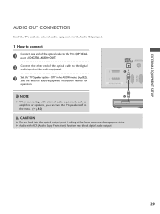
... ACP (Audio Copy Protection) function may damage your vision. EXTERNAL EQUIPMENT SETUP (CONTROL & SERVICE) AUDIO OUT CONNECTION Send the TV's audio to the digital audio input on the audio equipment. 3 Set the "TV Speaker option -
... ACP (Audio Copy Protection) function may damage your vision. EXTERNAL EQUIPMENT SETUP (CONTROL & SERVICE) AUDIO OUT CONNECTION Send the TV's audio to the digital audio input on the audio equipment. 3 Set the "TV Speaker option -
Owner's Manual
Page 30
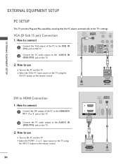
... PC to the HDMI/DVI IN 1, 2 or 3 jack on the TV. 2 Connect the PC audio output to use I Select the RGB-PC input source on the TV using the INPUT button on the PC and the TV. I Turn on the remote control. 30 OPTICAL AUDIO IN DIGITAL AUDIO OUT (RGB/DVI) 2 1 HDMI... output of the PC to the RGB IN (P C) jack on the TV. 2 1 VIDEO COMPONEN 1 2 Connect the PC audio output to use I Select the HDMI1, 2 or 3 input source on the TV using the INPUT button on the PC and the TV.
... PC to the HDMI/DVI IN 1, 2 or 3 jack on the TV. 2 Connect the PC audio output to use I Select the RGB-PC input source on the TV using the INPUT button on the PC and the TV. I Turn on the remote control. 30 OPTICAL AUDIO IN DIGITAL AUDIO OUT (RGB/DVI) 2 1 HDMI... output of the PC to the RGB IN (P C) jack on the TV. 2 1 VIDEO COMPONEN 1 2 Connect the PC audio output to use I Select the HDMI1, 2 or 3 input source on the TV using the INPUT button on the PC and the TV.
Owner's Manual
Page 31
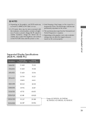
....020 1600x1200 74.537 59.869 1920x1080 66.587 59.934 Except 42/50PJ250, 42/50PJ340, 42/50PJ350, 42/50PJ550, 42/50PJ350C 31 G The synchronization input form for a long period of time. EXTERNAL EQUIPMENT SETUP !
....020 1600x1200 74.537 59.869 1920x1080 66.587 59.934 Except 42/50PJ250, 42/50PJ340, 42/50PJ350, 42/50PJ550, 42/50PJ350C 31 G The synchronization input form for a long period of time. EXTERNAL EQUIPMENT SETUP !
Owner's Manual
Page 36
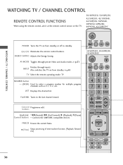
..., 42/50PJ340, 42/50PJ550, 50PK340, 50PK350, 60PK280, 60PK290, 42/50PJ350C POWER Turns the TV on from standby or off to standby. INPUT Also switches the TV on from standby. G p.49 TV Select the remote operating mode: TV NUMBER button - (DASH) Used to the...RATIO FLASHBK P CH A G E MUTE MENU INFO Q.MENU ENTER BACK EXIT FREEZE 36 ON/OFF Illuminates the remote control buttons. AV MODE Toggles through inputs. buttons SIMPLINK FF (Rewind), GG (Fast Forward), G (Playback), l l (Pause) Control buttons Controls the SIMPLINK compatible devices. Colored Programme edit. ...
..., 42/50PJ340, 42/50PJ550, 50PK340, 50PK350, 60PK280, 60PK290, 42/50PJ350C POWER Turns the TV on from standby or off to standby. INPUT Also switches the TV on from standby. G p.49 TV Select the remote operating mode: TV NUMBER button - (DASH) Used to the...RATIO FLASHBK P CH A G E MUTE MENU INFO Q.MENU ENTER BACK EXIT FREEZE 36 ON/OFF Illuminates the remote control buttons. AV MODE Toggles through inputs. buttons SIMPLINK FF (Rewind), GG (Fast Forward), G (Playback), l l (Pause) Control buttons Controls the SIMPLINK compatible devices. Colored Programme edit. ...

Owner's Manual
Page 38
... First, connect power cord correctly. CHANNEL SELECTION 1 Press the CH ( or ) or NUMBER buttons to turn TV on, press the , INPUT, CH ( or ) button on the TV or press the POWER, INPUT, CH( or ), Number (0~9) button on the remote control. 2 Select the viewing source by pressing the MUTE or VOL (+ or -) ... adjust the volume. 2 If you intend to switch the sound off, press the MUTE button. 3 You can cancel the Mute function by using the INPUT button on the remote control. 3 When finished using the TV, press the POWER button on vacation, disconnect the power plug from the wall power outlet...
... First, connect power cord correctly. CHANNEL SELECTION 1 Press the CH ( or ) or NUMBER buttons to turn TV on, press the , INPUT, CH ( or ) button on the TV or press the POWER, INPUT, CH( or ), Number (0~9) button on the remote control. 2 Select the viewing source by pressing the MUTE or VOL (+ or -) ... adjust the volume. 2 If you intend to switch the sound off, press the MUTE button. 3 You can cancel the Mute function by using the INPUT button on the remote control. 3 When finished using the TV, press the POWER button on vacation, disconnect the power plug from the wall power outlet...

