
Specification (English)
Page 2
.../30p/24p - LCD TV 47LH50 47" Full HD 1080p Broadband 120Hz LCD TV (47.0" diagonal) LGusa.com LCD SPECIFICATION Screen Size (Class) 47" Class (47.0" diagonal) Native ... 1 RS-232c In (Control/Service) 1 CABINET/ACCESSORIES Cabinet Color Glossy Black Swivel Stand (degrees) 20º / 20º VESA® Compliant (WxH) 200mm x 200mm Remote Control Type Unified POWER Voltage,... (When no video is a registered trademark of their respective owners. 09/11/09 LG Electronics U.S.A., Inc. 1000 Sylvan Avenue Englewood Cliffs, NJ 07632 Customer Service and Technical...
.../30p/24p - LCD TV 47LH50 47" Full HD 1080p Broadband 120Hz LCD TV (47.0" diagonal) LGusa.com LCD SPECIFICATION Screen Size (Class) 47" Class (47.0" diagonal) Native ... 1 RS-232c In (Control/Service) 1 CABINET/ACCESSORIES Cabinet Color Glossy Black Swivel Stand (degrees) 20º / 20º VESA® Compliant (WxH) 200mm x 200mm Remote Control Type Unified POWER Voltage,... (When no video is a registered trademark of their respective owners. 09/11/09 LG Electronics U.S.A., Inc. 1000 Sylvan Avenue Englewood Cliffs, NJ 07632 Customer Service and Technical...
Owner's Manual (English)
Page 6
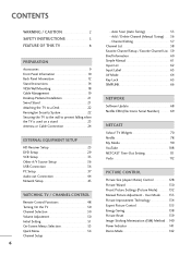
... 29 VCR Setup 33 Other A/V Source Setup 36 USB Connection 36 PC Setup 37 Audio out Connection 44 Network Setup 45 WATCHING TV / CHANNEL CONTROL Remote Control Functions 48 Turning On the TV 50 Channel Selection 50 Volume Adjustment 50 Initial Setting 51 On-Screen Menus Selection 53 Quick Menu 54 Channel Setup 6 - Channel Editing...
... 29 VCR Setup 33 Other A/V Source Setup 36 USB Connection 36 PC Setup 37 Audio out Connection 44 Network Setup 45 WATCHING TV / CHANNEL CONTROL Remote Control Functions 48 Turning On the TV 50 Channel Selection 50 Volume Adjustment 50 Initial Setting 51 On-Screen Menus Selection 53 Quick Menu 54 Channel Setup 6 - Channel Editing...
Owner's Manual (English)
Page 9
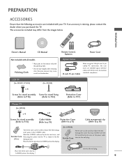
... models Polishing Cloth * Wipe spots on the display. (For 60PS80) Ferrite Core (Black) Ferrite core can be used to reduce the electromag- LCD TV (For 42LH50, 47LH50) (For 42LH50) x 4 Screws for stand assembly Screw for stand fixing (Refer to P.16) (Refer to P.22) Protection Cover (Refer to...ferrite core close to S-VIDEO jack on the display. Excessive pressure may differ from the images below. close to the wall plug. 9 Remote Control, Batteries Power Cord Option Extras D-sub 15 pin Cable When using the VGA (D-sub 15 pin cable) PC connection, the user must ...
... models Polishing Cloth * Wipe spots on the display. (For 60PS80) Ferrite Core (Black) Ferrite core can be used to reduce the electromag- LCD TV (For 42LH50, 47LH50) (For 42LH50) x 4 Screws for stand assembly Screw for stand fixing (Refer to P.16) (Refer to P.22) Protection Cover (Refer to...ferrite core close to S-VIDEO jack on the display. Excessive pressure may differ from the images below. close to the wall plug. 9 Remote Control, Batteries Power Cord Option Extras D-sub 15 pin Cable When using the VGA (D-sub 15 pin cable) PC connection, the user must ...
Owner's Manual (English)
Page 10
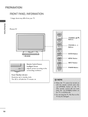
... Button POWER Button ! The floor or the TV may differ from your TV. The LED is switched off while the TV remains on the TV is off ). PREPARATION PREPARATION FRONT PANEL INFORMATION I Image shown may be turned on with the remote control, press the (POWER) button on the TV (The remote control will not work when the (POWER) button...
... Button POWER Button ! The floor or the TV may differ from your TV. The LED is switched off while the TV remains on the TV is off ). PREPARATION PREPARATION FRONT PANEL INFORMATION I Image shown may be turned on with the remote control, press the (POWER) button on the TV (The remote control will not work when the (POWER) button...
Owner's Manual (English)
Page 11
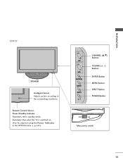
Illuminates blue when the TV is switched on. (Can be adjusted using the Power Indicator in standby mode. G p.141) CH VOL ENTER MENU INPUT CHANNEL (D,E) Buttons VOLUME (+, -) Buttons ENTER Button MENU Button INPUT Button POWER Button OFF ON Main power switch 11 PREPARATION LCD TV SPEAKER Intelligent Sensor Adjusts picture according to the surrounding conditions Remote Control Sensor, Power/Standby Indicator Illuminates red in the OPTION menu.
Illuminates blue when the TV is switched on. (Can be adjusted using the Power Indicator in standby mode. G p.141) CH VOL ENTER MENU INPUT CHANNEL (D,E) Buttons VOLUME (+, -) Buttons ENTER Button MENU Button INPUT Button POWER Button OFF ON Main power switch 11 PREPARATION LCD TV SPEAKER Intelligent Sensor Adjusts picture according to the surrounding conditions Remote Control Sensor, Power/Standby Indicator Illuminates red in the OPTION menu.

Owner's Manual (English)
Page 13
... Analog PC Connection. Uses a D-sub 15 pin cable (VGA cable). Also used for use with amps and home theater systems. 11 REMOTE CONTROL IN PORT For a wired remote control. 12 Power Cord Socket For operation with amps and home theater systems. Note: In standby mode, this port doesn't work. 6 ANTENNA/...CABLE IN Connect over-the air signals to this jack. Accepts DVI video using an adapter or HDMI to operate the TV on local network....
... Analog PC Connection. Uses a D-sub 15 pin cable (VGA cable). Also used for use with amps and home theater systems. 11 REMOTE CONTROL IN PORT For a wired remote control. 12 Power Cord Socket For operation with amps and home theater systems. Note: In standby mode, this port doesn't work. 6 ANTENNA/...CABLE IN Connect over-the air signals to this jack. Accepts DVI video using an adapter or HDMI to operate the TV on local network....
Owner's Manual (English)
Page 25
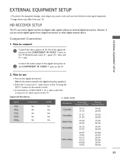
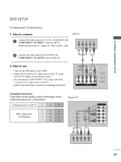
... digital set -top box to 2 the COMPONENT IN AUDIO 1 jacks on the TV. Component Connection 1. Connect the audio output of the digital settop box to COMPONENT IN 2 input, select the Component2 input source on the remote control. Supported Resolutions Y, CB/PB, CR/PR Signal 480i 480p 720p 1080i 1080p Component... Yes Yes Yes Yes Yes HDMI No Yes Yes Yes Yes Resolution Horizontal Frequency(KHz) 720x480i 720x480p 1280x720p 15.73 15.73 31.47 31.50 44.96 45.00...
... digital set -top box to 2 the COMPONENT IN AUDIO 1 jacks on the TV. Component Connection 1. Connect the audio output of the digital settop box to COMPONENT IN 2 input, select the Component2 input source on the remote control. Supported Resolutions Y, CB/PB, CR/PR Signal 480i 480p 720p 1080i 1080p Component... Yes Yes Yes Yes Yes HDMI No Yes Yes Yes Yes Resolution Horizontal Frequency(KHz) 720x480i 720x480p 1280x720p 15.73 15.73 31.47 31.50 44.96 45.00...
Owner's Manual (English)
Page 27
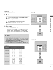
...44.1KHz,48KHz) HDMI-DTV Resolution Horizontal Vertical Frequency(KHz) Frequency(Hz) 720x480p 1280x720p 1920x1080i 1920x1080p 31.47 31.50 44.96 45.00 33.72 33.75 26.97 27.00 33.71 33.75 67...59.94 60.00 59.94 60.00 23.976 24.00 29.97 30.00 59.94 60.00 EXTERNAL EQUIPMENT SETUP LCD TV AV IN 1 VIDEO L(MONO) AUDIO R 3 2 L R 1 EO AUDIO OMPONENT IN /DVI IN RGB IN (PC)... on the TV using the INPUT button on the TV. How to connect 1 Connect the digital set-top box to the owner's manual for the digital set -top box. (Refer to HDMI/DVI IN 1, 2, 3, or 4 jack on the remote control. !
...44.1KHz,48KHz) HDMI-DTV Resolution Horizontal Vertical Frequency(KHz) Frequency(Hz) 720x480p 1280x720p 1920x1080i 1920x1080p 31.47 31.50 44.96 45.00 33.72 33.75 26.97 27.00 33.71 33.75 67...59.94 60.00 59.94 60.00 23.976 24.00 29.97 30.00 59.94 60.00 EXTERNAL EQUIPMENT SETUP LCD TV AV IN 1 VIDEO L(MONO) AUDIO R 3 2 L R 1 EO AUDIO OMPONENT IN /DVI IN RGB IN (PC)... on the TV using the INPUT button on the TV. How to connect 1 Connect the digital set-top box to the owner's manual for the digital set -top box. (Refer to HDMI/DVI IN 1, 2, 3, or 4 jack on the remote control. !
Owner's Manual (English)
Page 28
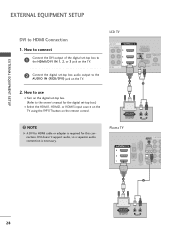
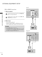
DVI doesn't support audio, so a separate audio connection is required for the digital set -top box. (Refer to the owner's manual for this connection. LCD TV AV IN 1 L(MONO) AUDIO R 3 2 L R 1 AUDIO NT IN () /DVI IN RGB IN (PC) AUDIO IN (RGB/DVI) OPTICAL DIGITA AUDIO OUT ANTENNA... 1 2 28 DVI OUTPUT L R AUDIO NOTE G A DVI to use I Select the HDMI1, HDMI2, or HDMI3 input source on the TV using the INPUT button on the remote control. ! EXTERNAL EQUIPMENT SETUP EXTERNAL EQUIPMENT SETUP DVI to the AUDIO IN (RGB/DVI) jack on the digital set -top box.) I Turn on...
DVI doesn't support audio, so a separate audio connection is required for the digital set -top box. (Refer to the owner's manual for this connection. LCD TV AV IN 1 L(MONO) AUDIO R 3 2 L R 1 AUDIO NT IN () /DVI IN RGB IN (PC) AUDIO IN (RGB/DVI) OPTICAL DIGITA AUDIO OUT ANTENNA... 1 2 28 DVI OUTPUT L R AUDIO NOTE G A DVI to use I Select the HDMI1, HDMI2, or HDMI3 input source on the TV using the INPUT button on the remote control. ! EXTERNAL EQUIPMENT SETUP EXTERNAL EQUIPMENT SETUP DVI to the AUDIO IN (RGB/DVI) jack on the digital set -top box.) I Turn on...
Owner's Manual (English)
Page 29
...DVD to the COMPONENT IN AUDIO 1 jacks on the remote control. Match the jack colors (Y = green, PB = blue, and PR = red). How to COMPONENT IN 2 input, select the Component2 input source on DVD player Y PB PR Y B-Y R-Y Y Cb Cr Y Pb Pr Plasma TV ( ) AUDIO IN COMPONENT IN (RGB/DVI) Y...VIDEO 1 jacks on the DVD player, insert a DVD. I If connected to use I Select the Component1 input source on the TV using the INPUT button on the TV. 2. LCD TV Y PB PR L R 2 Connect the audio outputs of the DVD to the component input ports as shown below. EXTERNAL EQUIPMENT ...
...DVD to the COMPONENT IN AUDIO 1 jacks on the remote control. Match the jack colors (Y = green, PB = blue, and PR = red). How to COMPONENT IN 2 input, select the Component2 input source on DVD player Y PB PR Y B-Y R-Y Y Cb Cr Y Pb Pr Plasma TV ( ) AUDIO IN COMPONENT IN (RGB/DVI) Y...VIDEO 1 jacks on the DVD player, insert a DVD. I If connected to use I Select the Component1 input source on the TV using the INPUT button on the TV. 2. LCD TV Y PB PR L R 2 Connect the audio outputs of the DVD to the component input ports as shown below. EXTERNAL EQUIPMENT ...
Owner's Manual (English)
Page 30
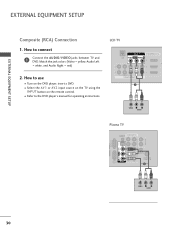
EXTERNAL EQUIPMENT SETUP ( ) EXTERNAL EQUIPMENT SETUP Composite (RCA) Connection 1. I Turn on the remote control. LCD TV AV IN 1 LAN VIDEO L(MONO) AUDIO R 3 2 2 L R 1 1 VIDEO AUDIO COMPONENT IN () 1 /DVI IN A ( VIDEO L R AUDIO Plasma TV AUDIO OUT ( ) AUDIO IN COMPONENT IN (RGB/DVI) L UT R Y VIDEO PB L PR RGB IN (PC) R AUDIO L(MONO) VIDEO S-VIDEO SERVICE AV IN 1 1 ONLY R L AUDIO...
EXTERNAL EQUIPMENT SETUP ( ) EXTERNAL EQUIPMENT SETUP Composite (RCA) Connection 1. I Turn on the remote control. LCD TV AV IN 1 LAN VIDEO L(MONO) AUDIO R 3 2 2 L R 1 1 VIDEO AUDIO COMPONENT IN () 1 /DVI IN A ( VIDEO L R AUDIO Plasma TV AUDIO OUT ( ) AUDIO IN COMPONENT IN (RGB/DVI) L UT R Y VIDEO PB L PR RGB IN (PC) R AUDIO L(MONO) VIDEO S-VIDEO SERVICE AV IN 1 1 ONLY R L AUDIO...
Owner's Manual (English)
Page 31
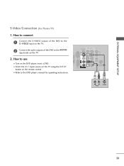
.../DVI) AL AL OUT VIDEO PB L PR RGB IN (PC) R AUDIO L(MONO) VIDEO S-VIDEO N SERVICE AV IN 1 1 ONLY R L AUDIO REMOTE CONTROL IN 1 ACNATBELNENIAN/2 2 L R AUDIO S-VIDEO () 31 () EXTERNAL EQUIPMENT SETUP S-Video Connection (For Plasma TV) 1. How to the AUDIO input jacks on the DVD player, insert a DVD. How to connect 1 Connect the S-VIDEO output...
.../DVI) AL AL OUT VIDEO PB L PR RGB IN (PC) R AUDIO L(MONO) VIDEO S-VIDEO N SERVICE AV IN 1 1 ONLY R L AUDIO REMOTE CONTROL IN 1 ACNATBELNENIAN/2 2 L R AUDIO S-VIDEO () 31 () EXTERNAL EQUIPMENT SETUP S-Video Connection (For Plasma TV) 1. How to the AUDIO input jacks on the DVD player, insert a DVD. How to connect 1 Connect the S-VIDEO output...
Owner's Manual (English)
Page 32
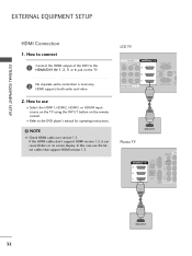
... to connect 1 Connect the HDMI output of the DVD to the HDMI/DVI IN 1, 2, 3 or 4 jack on the remote control. How to the DVD player's manual for operating instructions. ! NOTE G Check HDMI cable over version 1.3. LCD TV AV IN 1 VIDEO L(MONO) AUDIO R 3 2 L R 1 O AUDIO MPONENT IN /DVI IN RGB IN (PC) AUDIO IN (RGB/DVI...
... to connect 1 Connect the HDMI output of the DVD to the HDMI/DVI IN 1, 2, 3 or 4 jack on the remote control. How to the DVD player's manual for operating instructions. ! NOTE G Check HDMI cable over version 1.3. LCD TV AV IN 1 VIDEO L(MONO) AUDIO R 3 2 L R 1 O AUDIO MPONENT IN /DVI IN RGB IN (PC) AUDIO IN (RGB/DVI...
Owner's Manual (English)
Page 33
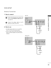
... I Insert a video tape into the VCR and press PLAY on the TV. I Set VCR output switch to 3 or 4 and then tune TV to the VCR owner's manual.) Plasma TV ANT OUT S-VIDEO VIDEO L R AUDIO ANT IN OUTPUT SWITCH Wall Jack 2 Antenna VIDEO L AUDIO O () REMOTE CONTROL IN 1 AUDIO ANTENNA/ CABLE IN ANT OUT S-VIDEO VIDEO L R AUDIO... CABLE IN 2. UDIO IN OPTICAL DIGITAL AUDIO OUT GB/DVI) 1 2 Connect the antenna cable to the RF antenna in socket of the ( ) VCR to connect LCD TV 1 Connect the RF antenna out socket of the VCR.
... I Insert a video tape into the VCR and press PLAY on the TV. I Set VCR output switch to 3 or 4 and then tune TV to the VCR owner's manual.) Plasma TV ANT OUT S-VIDEO VIDEO L R AUDIO ANT IN OUTPUT SWITCH Wall Jack 2 Antenna VIDEO L AUDIO O () REMOTE CONTROL IN 1 AUDIO ANTENNA/ CABLE IN ANT OUT S-VIDEO VIDEO L R AUDIO... CABLE IN 2. UDIO IN OPTICAL DIGITAL AUDIO OUT GB/DVI) 1 2 Connect the antenna cable to the RF antenna in socket of the ( ) VCR to connect LCD TV 1 Connect the RF antenna out socket of the VCR.
Owner's Manual (English)
Page 34
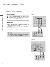
...Composite (RCA) Connection 1. How to AV IN 2, select AV2 input source on the TV. 2 2 L R 1 1 VIDEO AUDIO COMPONENT IN 1 ! How to use I Insert a video tape into the VCR and press PLAY on the remote control. Match the jack colors (Video = yellow, Audio Left = white, and Audio Right ...= red) AV IN 1 LAN VIDEO L(MONO) AUDIO R 3 /DVI I Select the A V 1 input source on the TV using the INPUT button on the VCR. (Refer to the AUDIO L/MONO jack of the TV. I If connected to connect LCD TV...
...Composite (RCA) Connection 1. How to AV IN 2, select AV2 input source on the TV. 2 2 L R 1 1 VIDEO AUDIO COMPONENT IN 1 ! How to use I Insert a video tape into the VCR and press PLAY on the remote control. Match the jack colors (Video = yellow, Audio Left = white, and Audio Right ...= red) AV IN 1 LAN VIDEO L(MONO) AUDIO R 3 /DVI I Select the A V 1 input source on the TV using the INPUT button on the VCR. (Refer to the AUDIO L/MONO jack of the TV. I If connected to connect LCD TV...

Owner's Manual (English)
Page 35
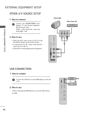
...Select the A V 1 input source on the TV using the INPUT button on the TV. () 2. AUDIO OUT R PTICAL IGITAL DIO OUT AUDIO IN COMPONENT IN (RGB/DVI) PB Y VIDEO L PR RGB IN (PC) R AUDIO L(MONO) VIDEO S-VIDEO LAN SERVICE AV IN 1 1 ONLY R L REMOTE CONTROL IN AUDIO ANTENNA/ CABLE IN 2 1 2 ...! Use it when available. ANT IN VIDEO L R AUDIO ANT OUT S-VIDEO OUTPUT SWITCH () 35 How to connect 1 Connect the S-VIDEO output of the VCR to the S -VIDEO input on the TV. 2 Connect the audio outputs of...
...Select the A V 1 input source on the TV using the INPUT button on the TV. () 2. AUDIO OUT R PTICAL IGITAL DIO OUT AUDIO IN COMPONENT IN (RGB/DVI) PB Y VIDEO L PR RGB IN (PC) R AUDIO L(MONO) VIDEO S-VIDEO LAN SERVICE AV IN 1 1 ONLY R L REMOTE CONTROL IN AUDIO ANTENNA/ CABLE IN 2 1 2 ...! Use it when available. ANT IN VIDEO L R AUDIO ANT OUT S-VIDEO OUTPUT SWITCH () 35 How to connect 1 Connect the S-VIDEO output of the VCR to the S -VIDEO input on the TV. 2 Connect the audio outputs of...
Owner's Manual (English)
Page 36
... jack, you use I After connecting the USB I Select the A V 2 input source on the TV using the INPUT button on the TV. How to connect 1 Connect the AUDIO/VIDEO jacks between TV and external equipment. Match the jack colors. (Video = yellow, Audio Left = white, and Audio ... AV IN 2 36 I Operate the corresponding external equipment. I If connected to AV IN 1 input, select the A V 1 input source on the remote control. USB IN IN 4 Camcorder Video Game Set VIDEO L R 1 EXTERNAL EQUIPMENT SETUP VIDEO L/MONO AUDIO R AV IN 2 USB CONNECTION 1. EXTERNAL EQUIPMENT SETUP OTHER ...
... jack, you use I After connecting the USB I Select the A V 2 input source on the TV using the INPUT button on the TV. How to connect 1 Connect the AUDIO/VIDEO jacks between TV and external equipment. Match the jack colors. (Video = yellow, Audio Left = white, and Audio ... AV IN 2 36 I Operate the corresponding external equipment. I If connected to AV IN 1 input, select the A V 1 input source on the remote control. USB IN IN 4 Camcorder Video Game Set VIDEO L R 1 EXTERNAL EQUIPMENT SETUP VIDEO L/MONO AUDIO R AV IN 2 USB CONNECTION 1. EXTERNAL EQUIPMENT SETUP OTHER ...
Owner's Manual (English)
Page 37
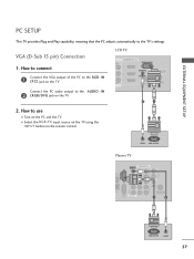
...AUDIO IN 2 (RGB/DVI) jack on the TV. 2 1 2. LCD TV 1 ( ) UDIO R 3 2 R 1 DIO /DVI IN RGB IN (PC) AUDIO IN (RGB/DVI) OPTICAL DIGITAL AUDIO OUT ANTENNA/ SERVICE ONLY CABLE IN Connect the PC audio output to the TV's settings. AUDIO RGB OUTPUT Plasma TV AUDIO OUT R ( ) PTICAL IGITAL DIO ... PR RGB IN (PC) R AUDIO L(MONO) VIDEO S-VIDEO LAN SERVICE AV IN 1 1 ONLY R L REMOTE CONTROL IN AUDIO ANTENNA/ CABLE IN 2 1 2 RGB OUTPUT AUDIO 37 How to the RGB IN (P C) jack on the TV. How to connect 1 Connect the VGA output of the PC to use I Select the RGB-PC input...
...AUDIO IN 2 (RGB/DVI) jack on the TV. 2 1 2. LCD TV 1 ( ) UDIO R 3 2 R 1 DIO /DVI IN RGB IN (PC) AUDIO IN (RGB/DVI) OPTICAL DIGITAL AUDIO OUT ANTENNA/ SERVICE ONLY CABLE IN Connect the PC audio output to the TV's settings. AUDIO RGB OUTPUT Plasma TV AUDIO OUT R ( ) PTICAL IGITAL DIO ... PR RGB IN (PC) R AUDIO L(MONO) VIDEO S-VIDEO LAN SERVICE AV IN 1 1 ONLY R L REMOTE CONTROL IN AUDIO ANTENNA/ CABLE IN 2 1 2 RGB OUTPUT AUDIO 37 How to the RGB IN (P C) jack on the TV. How to connect 1 Connect the VGA output of the PC to use I Select the RGB-PC input...
Owner's Manual (English)
Page 38
... HDMI1, HDMI2, or HDMI3 input source on the TV using the INPUT button on the remote control. ! LCD TV AV IN 1 VIDEO L(MONO) AUDIO R 3 2 L R 1 O AUDIO MPONENT IN () /DVI IN RGB IN (PC) AUDIO IN (RGB/DVI) OPTI AU ANT SERVICE ONLY CA 1 2 Plasma TV DVI OUTPUT AUDIO PR RGB IN (PC) R ...2 R 1 LAN SERVICE AV IN 1 1 2 ONLY 1 2 38 DVI OUTPUT AUDIO How to the HDMI/DVI IN 1, 2, or 3 jack on the TV. NOTE G Check HDMI cable over version 1.3. I Turn on the PC and the TV. EXTERNAL EQUIPMENT SETUP EXTERNAL EQUIPMENT SETUP DVI to the AUDIO IN 2 (RGB/DVI) jack on the...
... HDMI1, HDMI2, or HDMI3 input source on the TV using the INPUT button on the remote control. ! LCD TV AV IN 1 VIDEO L(MONO) AUDIO R 3 2 L R 1 O AUDIO MPONENT IN () /DVI IN RGB IN (PC) AUDIO IN (RGB/DVI) OPTI AU ANT SERVICE ONLY CA 1 2 Plasma TV DVI OUTPUT AUDIO PR RGB IN (PC) R ...2 R 1 LAN SERVICE AV IN 1 1 2 ONLY 1 2 38 DVI OUTPUT AUDIO How to the HDMI/DVI IN 1, 2, or 3 jack on the TV. NOTE G Check HDMI cable over version 1.3. I Turn on the PC and the TV. EXTERNAL EQUIPMENT SETUP EXTERNAL EQUIPMENT SETUP DVI to the AUDIO IN 2 (RGB/DVI) jack on the...
Owner's Manual (English)
Page 44
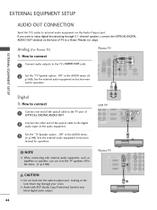
...L 1 R LAN SERVICE AV IN 1 1 2 ONLY Y 2 44 L R AUDIO LCD TV ( ) 3 2 L R 1 AUDIO T IN AUDIO IN (RGB/DVI) OPTICAL DIGITAL AUDIO OUT AN1TENNA/ SERVICE ONLY CABLE IN 2 () ! If you can turn the TV speakers off in the menu. (G p.149) CAUTION G Do not look into the optical ..." in the AUDIO menu. (G p.149). Plasma TV AUDIO OUT R OPTICAL DIGITAL VI IN AUDIO OUT AUDIO IN COMPONENT IN (RGB/DVI) PB Y VIDEO L PR RGB IN (PC) R AUDIO L(MONO) VIDEO S-VIDEO 1 LAN SERVICE AV IN 1 1 ONLY R L AUDIO REMOTE CONTROL IN ANTENNA/ CABLE IN 2 EXTERNAL EQUIPMENT SETUP ()...
...L 1 R LAN SERVICE AV IN 1 1 2 ONLY Y 2 44 L R AUDIO LCD TV ( ) 3 2 L R 1 AUDIO T IN AUDIO IN (RGB/DVI) OPTICAL DIGITAL AUDIO OUT AN1TENNA/ SERVICE ONLY CABLE IN 2 () ! If you can turn the TV speakers off in the menu. (G p.149) CAUTION G Do not look into the optical ..." in the AUDIO menu. (G p.149). Plasma TV AUDIO OUT R OPTICAL DIGITAL VI IN AUDIO OUT AUDIO IN COMPONENT IN (RGB/DVI) PB Y VIDEO L PR RGB IN (PC) R AUDIO L(MONO) VIDEO S-VIDEO 1 LAN SERVICE AV IN 1 1 ONLY R L AUDIO REMOTE CONTROL IN ANTENNA/ CABLE IN 2 EXTERNAL EQUIPMENT SETUP ()...

