
Owner's Manual (English)
Page 1
P/NO : SAC30708033 (0810-REV03) www.lgusa.com / www.lg.ca Record model number and serial number of the set . See the label attached on the back cover and quote this manual carefully before operating your dealer when you require service. LCD TV OWNER'S MANUAL 37LG50 42LG50 47LG50 52LG50 42LG50DC 47LG50DC 52LG50DC 42LG55 47LG55 Please read this information to your set . Retain it for future reference.
P/NO : SAC30708033 (0810-REV03) www.lgusa.com / www.lg.ca Record model number and serial number of the set . See the label attached on the back cover and quote this manual carefully before operating your dealer when you require service. LCD TV OWNER'S MANUAL 37LG50 42LG50 47LG50 52LG50 42LG50DC 47LG50DC 52LG50DC 42LG55 47LG55 Please read this information to your set . Retain it for future reference.
Owner's Manual (English)
Page 4
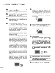
..., frayed power cords, or damaged or cracked wire insulation are not possible, have the cord replaced with liquids, such as this owner's manual to be connected to telephone wires, lightening rods, or gas pipes. Periodically examine the cord of this could result in fire or electric ...shock. Pay particular attention to install the TV by connecting it , discontinue use a damaged or loose power cord. on shelves above the unit). 17 GROUNDING Ensure that appliances be placed ...
..., frayed power cords, or damaged or cracked wire insulation are not possible, have the cord replaced with liquids, such as this owner's manual to be connected to telephone wires, lightening rods, or gas pipes. Periodically examine the cord of this could result in fire or electric ...shock. Pay particular attention to install the TV by connecting it , discontinue use a damaged or loose power cord. on shelves above the unit). 17 GROUNDING Ensure that appliances be placed ...
Owner's Manual (English)
Page 6
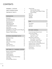
... Setup 23 Other A/V Source Setup 25 PC Setup 26 USB Connection 32 Audio Out Connection 33 WATCHING TV / CHANNEL CONTROL Remote Control Functions 34 Turning On the TV 36 Channel Selection 36 Volume Adjustment 36 Quick Menu / Favorite Channel Setup 37 Initial Setting 38 On-... Label 44 AV Mode 45 SIMPLINK 46 USB Entry Modes 48 Photo List 49 Music List 53 PICTURE CONTROL Picture Size (Aspect Ratio) Control 56 Preset Picture Settings - Eye Care 64 Advanced Control - Black (Darkness) Level 63 Advanced Control - Preset 59 Manual Picture Adjustment - Picture Mode - ...
... Setup 23 Other A/V Source Setup 25 PC Setup 26 USB Connection 32 Audio Out Connection 33 WATCHING TV / CHANNEL CONTROL Remote Control Functions 34 Turning On the TV 36 Channel Selection 36 Volume Adjustment 36 Quick Menu / Favorite Channel Setup 37 Initial Setting 38 On-... Label 44 AV Mode 45 SIMPLINK 46 USB Entry Modes 48 Photo List 49 Music List 53 PICTURE CONTROL Picture Size (Aspect Ratio) Control 56 Preset Picture Settings - Eye Care 64 Advanced Control - Black (Darkness) Level 63 Advanced Control - Preset 59 Manual Picture Adjustment - Picture Mode - ...

Owner's Manual (English)
Page 7
... & LANGUAGE CONTROL Auto Volume Leveler (Auto Volume 68 Preset Sound Settings (Sound Mode) 69 Sound Setting Adjustment - Auto Clock Setup 81 Manual Clock Setup 82 Auto On/Off Time Setting 83 Sleep Timer Setting 84 Auto Shut-off Setting 85 PARENTAL CONTROL / RATINGS Set Password &... Lock System 86 Channel Blocking 89 Movie & TV Rating 90 Downloadable Rating 95 External Input Blocking 96 Key lock 97 APPENDIX Troubleshooting 98 Maintenance 100 Product Specifications 101 Programming the Remote...
... & LANGUAGE CONTROL Auto Volume Leveler (Auto Volume 68 Preset Sound Settings (Sound Mode) 69 Sound Setting Adjustment - Auto Clock Setup 81 Manual Clock Setup 82 Auto On/Off Time Setting 83 Sleep Timer Setting 84 Auto Shut-off Setting 85 PARENTAL CONTROL / RATINGS Set Password &... Lock System 86 Channel Blocking 89 Movie & TV Rating 90 Downloadable Rating 95 External Input Blocking 96 Key lock 97 APPENDIX Troubleshooting 98 Maintenance 100 Product Specifications 101 Programming the Remote...
Owner's Manual (English)
Page 9
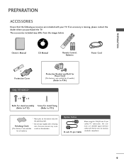
... not wipe roughly when removing Polishing Cloth stain. If an accessory is not available scratch or discoloration. RETURN TV Q. Owner's Manual CD Manual Remote Control, Batteries Power Cord or Protection Cover Protective Bracket and Bolt for Power Cord (This feature is ... signal interface cables with ferrite cores to P.15) * Wipe spots on the exterior only with your TV. The accessories included may cause (This feature is missing, please contact the dealer where you purchased the TV. MESNTUB MENU POWER DVD INPVUTCR ENTER VOL FAV AV MODE 1 4 MUTE 2 7 5 3 8...
... not wipe roughly when removing Polishing Cloth stain. If an accessory is not available scratch or discoloration. RETURN TV Q. Owner's Manual CD Manual Remote Control, Batteries Power Cord or Protection Cover Protective Bracket and Bolt for Power Cord (This feature is ... signal interface cables with ferrite cores to P.15) * Wipe spots on the exterior only with your TV. The accessories included may cause (This feature is missing, please contact the dealer where you purchased the TV. MESNTUB MENU POWER DVD INPVUTCR ENTER VOL FAV AV MODE 1 4 MUTE 2 7 5 3 8...
Owner's Manual (English)
Page 13
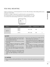
G When purchasing our wall mount kit, a detailed installation manual and all parts necessary for TV damage or personal injury when a non-VESA or non specified wall mount is used . G LG is not liable for assembly are shown in the table. CAUTION G Do not install your ... included with the VESA standard screw specifications. A B Product LCD TV Model 37LG5* 42LG5* 47LG5* 52LG5* VESA (A * B) Standard Screw Quantity 200 * 200 M6 4 800 * 400 M6 4 ! G Do not use an LG brand wall mount when mounting the TV to other building materials, please contact your nearest dealer.
G When purchasing our wall mount kit, a detailed installation manual and all parts necessary for TV damage or personal injury when a non-VESA or non specified wall mount is used . G LG is not liable for assembly are shown in the table. CAUTION G Do not install your ... included with the VESA standard screw specifications. A B Product LCD TV Model 37LG5* 42LG5* 47LG5* 52LG5* VESA (A * B) Standard Screw Quantity 200 * 200 M6 4 800 * 400 M6 4 ! G Do not use an LG brand wall mount when mounting the TV to other building materials, please contact your nearest dealer.
Owner's Manual (English)
Page 15
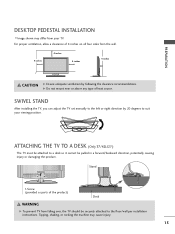
... 4 inches 4 inches 4 inches CAUTION G Ensure adequate ventilation by 20 degrees to the floor/wall per installation instructions. SWIVEL STAND After installing the TV, you can adjust the TV set manually to the left or right direction by following the clearance recommendations. Stand 1-Screw (provided as parts of heat source. Tipping, shaking, or rocking...
... 4 inches 4 inches 4 inches CAUTION G Ensure adequate ventilation by 20 degrees to the floor/wall per installation instructions. SWIVEL STAND After installing the TV, you can adjust the TV set manually to the left or right direction by following the clearance recommendations. Stand 1-Screw (provided as parts of heat source. Tipping, shaking, or rocking...
Owner's Manual (English)
Page 18
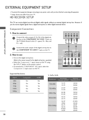
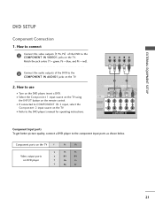
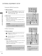
... Connect the video outputs (Y, PB, PR) of the digital set -top box. How to the COMPONENT IN VIDEO 1 jacks on the TV. HD RECEIVER SETUP This TV can receive digital over-the-air/digital cable signals without an external digital set -top box to the COMPONENT IN AUDIO 1 jacks on... the digital set-top box. (Refer to COMPONENT IN2 input, select the Component 2 input source on the TV. Component Connection 1. operation) I If connected to the owner's manual for the digital set -top box or other digital external device. Y PB PR L R 1 2 RGB IN RGB(PC) AUDIO ...
... Connect the video outputs (Y, PB, PR) of the digital set -top box. How to the COMPONENT IN VIDEO 1 jacks on the TV. HD RECEIVER SETUP This TV can receive digital over-the-air/digital cable signals without an external digital set -top box to the COMPONENT IN AUDIO 1 jacks on... the digital set-top box. (Refer to COMPONENT IN2 input, select the Component 2 input source on the TV. Component Connection 1. operation) I If connected to the owner's manual for the digital set -top box or other digital external device. Y PB PR L R 1 2 RGB IN RGB(PC) AUDIO ...

Owner's Manual (English)
Page 19
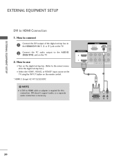
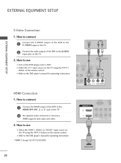
... set -top box.) I Select the HDMI1, HDMI2, or HDMI3* input source on the TV using the INPUT button on the TV. 2 No separate audio connection is necessary. How to connect 1 Connect the digital set-top box to the owner's manual for the digital set -top box. (Refer to HDMI/DVI IN1, 2, or 3* jack...
... set -top box.) I Select the HDMI1, HDMI2, or HDMI3* input source on the TV using the INPUT button on the TV. 2 No separate audio connection is necessary. How to connect 1 Connect the digital set-top box to the owner's manual for the digital set -top box. (Refer to HDMI/DVI IN1, 2, or 3* jack...
Owner's Manual (English)
Page 20
... 2 DVI-DTV OUTPUT L R 20 How to use I Turn on the digital set -top box.) I O (RGB/DVI) jack on the TV. 2. NOTE G A DVI to the owner's manual for this connection. EXTERNAL EQUIPMENT SETUP EXTERNAL EQUIPMENT SETUP DVI to the A U D I Select the HDMI1, HDMI2, or HDMI3* input source on ...the TV using the INPUT button on the remote control. * HDMI 3: Except 42/47/52LG50DC ! DVI doesn't support audio, ...
... 2 DVI-DTV OUTPUT L R 20 How to use I Turn on the digital set -top box.) I O (RGB/DVI) jack on the TV. 2. NOTE G A DVI to the owner's manual for this connection. EXTERNAL EQUIPMENT SETUP EXTERNAL EQUIPMENT SETUP DVI to the A U D I Select the HDMI1, HDMI2, or HDMI3* input source on ...the TV using the INPUT button on the remote control. * HDMI 3: Except 42/47/52LG50DC ! DVI doesn't support audio, ...
Owner's Manual (English)
Page 21
... jacks on the DVD player, insert a DVD. I If connected to the component input ports as shown below. I Select the Component 1 input source on the TV using the INPUT button on DVD player Y Y PB PR PB PR B-Y R-Y Cb Cr Pb Pr 21 How to connect 1 Connect the video outputs (Y, PB..., PR) of the DVD to use I Refer to the DVD player's manual for operating instructions. 1 2 RGB IN RGB(PC) AUDIO REMOT (RGB/DVI) CONTROL VI IN ( 2 Y 1 PB PR L R VIDEO AUDIO COMPONENT IN Component Input ...
... jacks on the DVD player, insert a DVD. I If connected to the component input ports as shown below. I Select the Component 1 input source on the TV using the INPUT button on DVD player Y Y PB PR PB PR B-Y R-Y Cb Cr Pb Pr 21 How to connect 1 Connect the video outputs (Y, PB..., PR) of the DVD to use I Refer to the DVD player's manual for operating instructions. 1 2 RGB IN RGB(PC) AUDIO REMOT (RGB/DVI) CONTROL VI IN ( 2 Y 1 PB PR L R VIDEO AUDIO COMPONENT IN Component Input ...
Owner's Manual (English)
Page 22
... the audio outputs of the DVD to use I Select the HDMI1, HDMI2, or HDMI3* input source on the TV using the INPUT button on the remote control. I Refer to the DVD player's manual for operating instructions. * HDMI 3: Except 42/47/52LG50DC RGB(PC) AUDIO (RGB/D HDMI/DVI IN 2 1... 2 Y 1 PB PR L VIDEO A COMPONENT IN 1 HDMI-DVD OUTPUT 22 I Select the A V 1 input source on the TV using the INPUT button on the TV. 2. EXTERNAL EQUIPMENT SETUP...
... the audio outputs of the DVD to use I Select the HDMI1, HDMI2, or HDMI3* input source on the TV using the INPUT button on the remote control. I Refer to the DVD player's manual for operating instructions. * HDMI 3: Except 42/47/52LG50DC RGB(PC) AUDIO (RGB/D HDMI/DVI IN 2 1... 2 Y 1 PB PR L VIDEO A COMPONENT IN 1 HDMI-DVD OUTPUT 22 I Select the A V 1 input source on the TV using the INPUT button on the TV. 2. EXTERNAL EQUIPMENT SETUP...
Owner's Manual (English)
Page 23
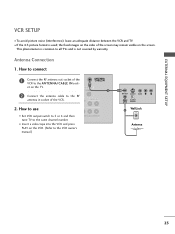
...out socket of the VCR to the RF antenna in socket of the screen may remain visible on the TV. I To avoid picture noise (interference), leave an adequate distance between the VCR and TV. UDIO OUT COAXIAL 1 2 Connect the antenna cable to the ANTENNA/CABLE IN sock- EXTERNAL EQUIPMENT ...SETUP VCR SETUP I Insert a video tape into the VCR and press PLAY on the VCR. (Refer to the VCR owner's manual.) EO L(MONO) AUDIO R ANT OUT S-...
...out socket of the VCR to the RF antenna in socket of the screen may remain visible on the TV. I To avoid picture noise (interference), leave an adequate distance between the VCR and TV. UDIO OUT COAXIAL 1 2 Connect the antenna cable to the ANTENNA/CABLE IN sock- EXTERNAL EQUIPMENT ...SETUP VCR SETUP I Insert a video tape into the VCR and press PLAY on the VCR. (Refer to the VCR owner's manual.) EO L(MONO) AUDIO R ANT OUT S-...
Owner's Manual (English)
Page 24
...have a mono VCR, connect the audio cable from the VCR to the AUDIO L/MONO jack of the VCR to the VCR owner's manual.) I Select the A V 1 input source on the TV using the INPUT button on the remote control. ANT IN S-VIDEO VIDEO L R ANT OUT OUTPUT SWITCH ANTENNA/ CABLE IN AUDIO REMOTE ...remote control. How to connect 1 Connect the S-VIDEO output of the VCR to the VCR owner's manual.) I Insert a video tape into the VCR and press PLAY on the VCR. (Refer to the S -VIDEO input on the TV. ! How to both Video and the S-Video cables, only the S-Video will work. CAUTION ...
...have a mono VCR, connect the audio cable from the VCR to the AUDIO L/MONO jack of the VCR to the VCR owner's manual.) I Select the A V 1 input source on the TV using the INPUT button on the remote control. ANT IN S-VIDEO VIDEO L R ANT OUT OUTPUT SWITCH ANTENNA/ CABLE IN AUDIO REMOTE ...remote control. How to connect 1 Connect the S-VIDEO output of the VCR to the VCR owner's manual.) I Insert a video tape into the VCR and press PLAY on the VCR. (Refer to the S -VIDEO input on the TV. ! How to both Video and the S-Video cables, only the S-Video will work. CAUTION ...
Owner's Manual (English)
Page 29
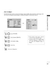
... after Auto adjustment in RGB-PC, you can adjust the Position, S i z e or P h a s e. 29 After adjustment, if the image is still not correct, try using the manual settings or a different resolution or refresh rate on the PC. EXTERNAL EQUIPMENT SETUP Auto Configure Automatically adjusts picture position and minimizes image instability.
... after Auto adjustment in RGB-PC, you can adjust the Position, S i z e or P h a s e. 29 After adjustment, if the image is still not correct, try using the manual settings or a different resolution or refresh rate on the PC. EXTERNAL EQUIPMENT SETUP Auto Configure Automatically adjusts picture position and minimizes image instability.
Owner's Manual (English)
Page 30
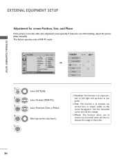
... Prev. Select Screen (RGB-PC). I Position: This function is not clear after auto adjustment and especially if characters are still trembling, adjust the picture phase manually. EXTERNAL EQUIPMENT SETUP EXTERNAL EQUIPMENT SETUP Adjustment for screen Position, Size, and Phase If the picture is to adjust picture to left/right and up...
... Prev. Select Screen (RGB-PC). I Position: This function is not clear after auto adjustment and especially if characters are still trembling, adjust the picture phase manually. EXTERNAL EQUIPMENT SETUP EXTERNAL EQUIPMENT SETUP Adjustment for screen Position, Size, and Phase If the picture is to adjust picture to left/right and up...

Owner's Manual (English)
Page 33
How to connect 1 Connect audio outputs to external audio equipment via the Audio Output port. See the external audio equipment instruction manual for operation. NOTE G When connecting with ACP(Audio Copy Protection) function. Looking at the laser beam may damage your vision. G Block the... SPDIF out (optical/coaxial) about the contents with external audio equipments, such as amplifiers or speakers, you can turn the TV speakers off in the menu. (G p.73) CAUTION G Do not look into the optical output port. Off" in the AUDIO menu. (G p.73). ...
How to connect 1 Connect audio outputs to external audio equipment via the Audio Output port. See the external audio equipment instruction manual for operation. NOTE G When connecting with ACP(Audio Copy Protection) function. Looking at the laser beam may damage your vision. G Block the... SPDIF out (optical/coaxial) about the contents with external audio equipments, such as amplifiers or speakers, you can turn the TV speakers off in the menu. (G p.73) CAUTION G Do not look into the optical output port. Off" in the AUDIO menu. (G p.73). ...
Owner's Manual (English)
Page 37
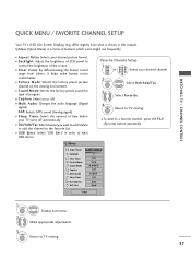
...I USB Eject: Select "USB Eject" in this manual. I Picture Mode: Selects the factory preset picture depend on or off automatically. MENU Return to TV viewing. 37 MENU 2 Display each menu. Make appropriate adjustments. 3 Q. MENU Return to TV viewing. I Sleep Timer: Select the amount of the... screen. I Sound Mode: Selects the factory preset sound for type of LCD panel to eject USB device. ...
...I USB Eject: Select "USB Eject" in this manual. I Picture Mode: Selects the factory preset picture depend on or off automatically. MENU Return to TV viewing. 37 MENU 2 Display each menu. Make appropriate adjustments. 3 Q. MENU Return to TV viewing. I Sleep Timer: Select the amount of the... screen. I Sound Mode: Selects the factory preset sound for type of LCD panel to eject USB device. ...
Owner's Manual (English)
Page 38
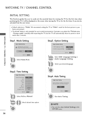
...OPTION menu. Mode Setting ! Time Setting Step2. Auto Tuning Auto Tuning can adjust the "Picture menu - Picture mode" manually while inspecting the TV, but the TV will be activated from the user menus. Option Setting Step3. Do you want to start Auto Tuning? We recommend setting ... time. Selecting the environment. Customers can change channel map. NOTE I Default selection is only intended for the first time when purchasing the TV. Choose the setting mode you want . OSD Language Setting 2. Time Setting Current Time Setting Year Month Date Hour Minute Time Zone Daylight ...
...OPTION menu. Mode Setting ! Time Setting Step2. Auto Tuning Auto Tuning can adjust the "Picture menu - Picture mode" manually while inspecting the TV, but the TV will be activated from the user menus. Option Setting Step3. Do you want to start Auto Tuning? We recommend setting ... time. Selecting the environment. Customers can change channel map. NOTE I Default selection is only intended for the first time when purchasing the TV. Choose the setting mode you want . OSD Language Setting 2. Time Setting Current Time Setting Year Month Date Hour Minute Time Zone Daylight ...
Owner's Manual (English)
Page 39
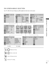
... CONTROL ON-SCREEN MENUS SELECTION Your TV's OSD (On Screen Display) may differ slightly from that shown in this manual. CHANNEL Auto Tuning Manual Tuning Channel Edit Move Enter PICTURE Move Aspect Ratio : 16:9 Picture Mode : Standard • Backlight 80 • Contrast 90 • ... Off Clear Voice : On Balance 0L R Sound Mode : Standard • SRS TruSurround XT: Off • Treble 50 • Bass 50 • Reset TV Speaker : On OPTION Language Input Label SIMPLINK Key Lock Caption Set ID Power Indicator Initial Setting Move Enter : English : On : Off : Off : 1 : ...
... CONTROL ON-SCREEN MENUS SELECTION Your TV's OSD (On Screen Display) may differ slightly from that shown in this manual. CHANNEL Auto Tuning Manual Tuning Channel Edit Move Enter PICTURE Move Aspect Ratio : 16:9 Picture Mode : Standard • Backlight 80 • Contrast 90 • ... Off Clear Voice : On Balance 0L R Sound Mode : Standard • SRS TruSurround XT: Off • Treble 50 • Bass 50 • Reset TV Speaker : On OPTION Language Input Label SIMPLINK Key Lock Caption Set ID Power Indicator Initial Setting Move Enter : English : On : Off : Off : 1 : ...


