User Manual
Page 4
... 9 Antenna Connection 10 Swivel Stand 10 EXTERNAL EQUIPMENT SETUP HD Receiver Setup 11 DVD Setup 13 VCR Setup 16 Insertion of CI Module 19 Digital Audio Out Setup 19 Other A/V Source Setup 20 Usb Setup 20 PC Setup 21 - Button Function in Extended Description Box . . 69 - Switch on the TV 32...
... 9 Antenna Connection 10 Swivel Stand 10 EXTERNAL EQUIPMENT SETUP HD Receiver Setup 11 DVD Setup 13 VCR Setup 16 Insertion of CI Module 19 Digital Audio Out Setup 19 Other A/V Source Setup 20 Usb Setup 20 PC Setup 21 - Button Function in Extended Description Box . . 69 - Switch on the TV 32...
User Manual
Page 5
... 86 Sound Setting Adjustment -User Mode 87 SRS TruSurround XT 87 Clear Voice II 88 Balance 88 TV Speakers On/ Off Setup 89 Selecting Digital Audio Out 90 Audio Reset 91 Audio description 92 I/II - NICAM Reception (In Analogue Mode Only) . . 94 -
... 86 Sound Setting Adjustment -User Mode 87 SRS TruSurround XT 87 Clear Voice II 88 Balance 88 TV Speakers On/ Off Setup 89 Selecting Digital Audio Out 90 Audio Reset 91 Audio description 92 I/II - NICAM Reception (In Analogue Mode Only) . . 94 -

User Manual
Page 8
...-232C port on a PC. Never attempt to operate the TV on DC power. 2 OPTICAL DIGITAL AUDIO OUT Connect digital audio to a Digital Audio Component. The voltage is not available in all countries.) 8 SERVICE ONLY PORT 6 Use an Optical audio cable. 3 Euro Scart Socket (AV1/AV2) Connect scart socket input or output from your TV...
...-232C port on a PC. Never attempt to operate the TV on DC power. 2 OPTICAL DIGITAL AUDIO OUT Connect digital audio to a Digital Audio Component. The voltage is not available in all countries.) 8 SERVICE ONLY PORT 6 Use an Optical audio cable. 3 Euro Scart Socket (AV1/AV2) Connect scart socket input or output from your TV...

User Manual
Page 9
... a PC. Connect an HDMI signal to these jacks. The voltage is used for Service or Hotel mode. 8 Component Input Connect a component video/audio device to these jacks. 5 HDMI Input Connect RF antenna to this jack. 10 PCMCIA (Personal Computer Memory Card International Association) Card Slot Insert the...Module to PCMCIA CARD SLOT. (This feature is not available in all countries.) 11 USB Input Connect USB storage device to HDMI cable. 12 Audio/Video Input Connect audio/video output from an external 6 RGB Input Connect the output from a PC or DTV. 7 RS-232C IN (CONTROL & SERVICE) PORT ...
... a PC. Connect an HDMI signal to these jacks. The voltage is used for Service or Hotel mode. 8 Component Input Connect a component video/audio device to these jacks. 5 HDMI Input Connect RF antenna to this jack. 10 PCMCIA (Personal Computer Memory Card International Association) Card Slot Insert the...Module to PCMCIA CARD SLOT. (This feature is not available in all countries.) 11 USB Input Connect USB storage device to HDMI cable. 12 Audio/Video Input Connect audio/video output from an external 6 RGB Input Connect the output from a PC or DTV. 7 RS-232C IN (CONTROL & SERVICE) PORT ...

User Manual
Page 12
... the TV, you can adjust the TV manually to the left or right direction by 20 degrees to the antenna as shown above. VIDEO L/MONO AUDIO R S-VIDEO HDMI IN 3 AV IN 3 Wall Antenna Socket Multi-family Dwellings/Apartments (Connect to wall antenna socket) Outdoor Antenna (VHF, UHF) RF Coaxial Wire (75...
... the TV, you can adjust the TV manually to the left or right direction by 20 degrees to the antenna as shown above. VIDEO L/MONO AUDIO R S-VIDEO HDMI IN 3 AV IN 3 Wall Antenna Socket Multi-family Dwellings/Apartments (Connect to wall antenna socket) Outdoor Antenna (VHF, UHF) RF Coaxial Wire (75...
User Manual
Page 13
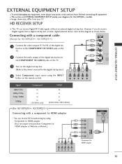
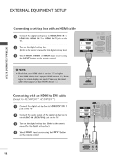
...1 Connect the video outputs (Y, PB, PR) of the digital set 1 top box to the COMPONENT IN VIDEO jacks on the TV. 2 Connect the audio output of the digital set -top box or other digital external device, refer to the diagram as shown below. I Image shown may differ from a digital... set -top box to 2 the COMPONENT IN AUDIO jacks on the TV. 3 Turn on the remote control. However, if you have finished connecting all equipment. Connecting with a component to HDMI adapter *...
...1 Connect the video outputs (Y, PB, PR) of the digital set 1 top box to the COMPONENT IN VIDEO jacks on the TV. 2 Connect the audio output of the digital set -top box or other digital external device, refer to the diagram as shown below. I Image shown may differ from a digital... set -top box to 2 the COMPONENT IN AUDIO jacks on the TV. 3 Turn on the remote control. However, if you have finished connecting all equipment. Connecting with a component to HDMI adapter *...
User Manual
Page 14
... 42/50PQ10**, 42/50PQ11**) 1 Connect the digital set-top box to HDMI/DVI IN 1 jack on the TV. 2 Connect the audio output of the digital set-top box to the AUDIO IN (RGB/DVI) jack on the TV. 3 Turn on the digital set-top box. (Refer to the owner's manual for the...
... 42/50PQ10**, 42/50PQ11**) 1 Connect the digital set-top box to HDMI/DVI IN 1 jack on the TV. 2 Connect the audio output of the digital set-top box to the AUDIO IN (RGB/DVI) jack on the TV. 3 Turn on the digital set-top box. (Refer to the owner's manual for the...

User Manual
Page 15
.../50PQ11**) 1 Connect the video outputs (Y, PB, PR) of the DVD to the COMPONENT IN VIDEO jacks on the TV. 2 Connect the audio outputs of the DVD to the COMPONENT IN AUDIO jacks on the TV. 3 Turn on the DVD player, insert a DVD. 4 Select Component input source using the INPUT button on DVD...
.../50PQ11**) 1 Connect the video outputs (Y, PB, PR) of the DVD to the COMPONENT IN VIDEO jacks on the TV. 2 Connect the audio outputs of the DVD to the COMPONENT IN AUDIO jacks on the TV. 3 Turn on the DVD player, insert a DVD. 4 Select Component input source using the INPUT button on DVD...

User Manual
Page 16
...Monitor Out) O O AV2 (When DTV scheduled recording is in progress using the INPUT button on the remote control. VIDEO L/MONO AUDIO R S-VIDEO HDMI IN 3 ! NOTE G Any Euro scart cable used must be signal shielded. 14 AV IN 3 Monitor Out...AV1 input source using recording equipment.) O O (The input mode is available. G AV3, Component, RGB : Except for operating instructions. AUDIO/ VIDEO (R) AUDIO (L) Input Scart Video Audio RGB AV1 O O O Output Video, Audio ATV only AV2 O O X ATV, DTV, AV1/2/3 output is converted to DTV automatically.) AV1/2/3 O O O Component/RGB/HDMI...
...Monitor Out) O O AV2 (When DTV scheduled recording is in progress using the INPUT button on the remote control. VIDEO L/MONO AUDIO R S-VIDEO HDMI IN 3 ! NOTE G Any Euro scart cable used must be signal shielded. 14 AV IN 3 Monitor Out...AV1 input source using recording equipment.) O O (The input mode is available. G AV3, Component, RGB : Except for operating instructions. AUDIO/ VIDEO (R) AUDIO (L) Input Scart Video Audio RGB AV1 O O O Output Video, Audio ATV only AV2 O O X ATV, DTV, AV1/2/3 output is converted to DTV automatically.) AV1/2/3 O O O Component/RGB/HDMI...

User Manual
Page 17
...3 Refer to the DVD player's manual for operating instructions. AV IN 3 Connecting the HDMI cable 1 Connect the HDMI output of the DVD to the AUDIO input jacks on the TV. 3 Turn on the remote control. 5 Refer to the DVD player's manual for operating instruc- G If the DVD does... your HDMI cable is version 1.3 or higher. If the HDMI cables don't support HDMI version 1.3, flickering or no screen display can receive video and audio signals simultaneously when using the INPUT button on the DVD player, insert a DVD. NOTE 1 G The TV can result. G Check that support at...
...3 Refer to the DVD player's manual for operating instructions. AV IN 3 Connecting the HDMI cable 1 Connect the HDMI output of the DVD to the AUDIO input jacks on the TV. 3 Turn on the remote control. 5 Refer to the DVD player's manual for operating instruc- G If the DVD does... your HDMI cable is version 1.3 or higher. If the HDMI cables don't support HDMI version 1.3, flickering or no screen display can receive video and audio signals simultaneously when using the INPUT button on the DVD player, insert a DVD. NOTE 1 G The TV can result. G Check that support at...

User Manual
Page 19
... in progress using the INPUT button on the remote control. 4 If connected to AV2 Euro scart socket, select AV2 input source. 1 AUDIO/ VIDEO (R) AUDIO (L) Input Scart Video Audio RGB AV1 O O O Output Video, Audio ATV only AV2 O O X ATV, DTV, AV1/2/3 output is converted to DTV automatically.) AV1/2/3 O O O Component/RGB/HDMI O X O G TV Out : Outputs analog TV...
... in progress using the INPUT button on the remote control. 4 If connected to AV2 Euro scart socket, select AV2 input source. 1 AUDIO/ VIDEO (R) AUDIO (L) Input Scart Video Audio RGB AV1 O O O Output Video, Audio ATV only AV2 O O X ATV, DTV, AV1/2/3 output is converted to DTV automatically.) AV1/2/3 O O O Component/RGB/HDMI O X O G TV Out : Outputs analog TV...

User Manual
Page 20
...VIDEO L R ANT IN OUTPUT SWITCH ANT OUT EXTERNAL EQUIPMENT SETUP Connecting with a S-Video cable (Except for 42/50PQ10**, 42/50PQ11**) 1 Connect the AUDIO/VIDEO jacks between TV and VCR. The picture quality is improved; compared to the S-VHS VCR simultaneously, only the S-VIDEO can be received. 18 ...S-VIDEO VIDEO L R ANT IN OUTPUT SWITCH ANT OUT 1 2 Match the jack colours (Video = yellow, Audio Left = white, and Audio Right = red) 2 Insert a video tape into the VCR and press PLAY on the VCR. (Refer to the VCR owner's manual.) 4 Select ...
...VIDEO L R ANT IN OUTPUT SWITCH ANT OUT EXTERNAL EQUIPMENT SETUP Connecting with a S-Video cable (Except for 42/50PQ10**, 42/50PQ11**) 1 Connect the AUDIO/VIDEO jacks between TV and VCR. The picture quality is improved; compared to the S-VHS VCR simultaneously, only the S-VIDEO can be received. 18 ...S-VIDEO VIDEO L R ANT IN OUTPUT SWITCH ANT OUT 1 2 Match the jack colours (Video = yellow, Audio Left = white, and Audio Right = red) 2 Insert a video tape into the VCR and press PLAY on the VCR. (Refer to the VCR owner's manual.) 4 Select ...

User Manual
Page 21
..., this can cause damage to PCMCIA (Personal Computer Memory Card International Association) CARD SLOT of the optical cable to the external audio equipment VI IN instruction manual for all countries. 1 1 Insert the CI Module to the TV and the PCMCIA card slot. DIGITAL... AUDIO OUT SETUP Sending the TV's audio signal to external audio equipment via the Digital Audio Output (Optical) port. For further information, see p.44. IN tal audio (Optical) input on the back of TV to a DVD Home Theater (or amp)....
..., this can cause damage to PCMCIA (Personal Computer Memory Card International Association) CARD SLOT of the optical cable to the external audio equipment VI IN instruction manual for all countries. 1 1 Insert the CI Module to the TV and the PCMCIA card slot. DIGITAL... AUDIO OUT SETUP Sending the TV's audio signal to external audio equipment via the Digital Audio Output (Optical) port. For further information, see p.44. IN tal audio (Optical) input on the back of TV to a DVD Home Theater (or amp)....

User Manual
Page 22
... TV and external equipment. After connecting the USB IN jacks, you use the U S B 1 2 function. (G p.53) VIDEO L/MONO AUDIO R S-VIDEO HDMI IN 3 20 AV IN 3 Match the jack colours. (Video = yellow, Audio Left = white, and Audio Right = red) 2 Select AV3 input source using the INPUT button on the side of TV. Refer to the...
... TV and external equipment. After connecting the USB IN jacks, you use the U S B 1 2 function. (G p.53) VIDEO L/MONO AUDIO R S-VIDEO HDMI IN 3 20 AV IN 3 Match the jack colours. (Video = yellow, Audio Left = white, and Audio Right = red) 2 Select AV3 input source using the INPUT button on the side of TV. Refer to the...

User Manual
Page 23
...for 42/50PQ10**, 42/50PQ11**) This TV provides Plug and Play capability, meaning that the PC adjusts automatically to the AUDIO IN (RGB/DVI) jack on the TV. 3 Turn on the PC and the TV 4 Select R G B input... cable 1 Connect the DVI output of the PC to the RGB IN (PC) jack on the TV. 2 Connect the PC audio output to the TV's settings. HDMI IN 2 1 HDMI/DVI IN 2 1 Connecting with a D-sub 15 pin cable 1 ...Connect the RGB output of the PC to the HDMI/DVI IN1 jack on the TV. 2 Connect the PC audio output to the AUDIO IN (RGB/DVI) jack on the TV. 3 Turn on the PC and the TV. 4 Select HDMI1 ...
...for 42/50PQ10**, 42/50PQ11**) This TV provides Plug and Play capability, meaning that the PC adjusts automatically to the AUDIO IN (RGB/DVI) jack on the TV. 3 Turn on the PC and the TV 4 Select R G B input... cable 1 Connect the DVI output of the PC to the RGB IN (PC) jack on the TV. 2 Connect the PC audio output to the TV's settings. HDMI IN 2 1 HDMI/DVI IN 2 1 Connecting with a D-sub 15 pin cable 1 ...Connect the RGB output of the PC to the HDMI/DVI IN1 jack on the TV. 2 Connect the PC audio output to the AUDIO IN (RGB/DVI) jack on the TV. 3 Turn on the PC and the TV. 4 Select HDMI1 ...

User Manual
Page 25
...interference relating to display the PC output on the menu until the picture is too long, there may become permanently imprinted on the TV. (Audio cables are separate. G The synchronization input waveform for the PC mode, they provide the best picture quality. EXTERNAL EQUIPMENT SETUP ! The ...fixed image may be interference on the screen. If the refresh rate of cable. G Connect the audio cable from the HDMI output port of time. We recommend using a sound card, adjust PC sound as required. G Connect the signal cable ...
...interference relating to display the PC output on the menu until the picture is too long, there may become permanently imprinted on the TV. (Audio cables are separate. G The synchronization input waveform for the PC mode, they provide the best picture quality. EXTERNAL EQUIPMENT SETUP ! The ...fixed image may be interference on the screen. If the refresh rate of cable. G Connect the audio cable from the HDMI output port of time. We recommend using a sound card, adjust PC sound as required. G Connect the signal cable ...

User Manual
Page 31
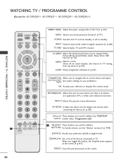
... cover. 29 control buttons Q. Do not mix old or used batteries with -). MENU Select the desired quick menu source. (Aspect Ratio, Picture Mode, Sound Mode, Audio, Sleep Timer, USB Eject.)(G p.33) INFO i Shows the present screen information. MARK Check and un-check programmes in the USB menu. (Except for 42/50PQ10...
... cover. 29 control buttons Q. Do not mix old or used batteries with -). MENU Select the desired quick menu source. (Aspect Ratio, Picture Mode, Sound Mode, Audio, Sleep Timer, USB Eject.)(G p.33) INFO i Shows the present screen information. MARK Check and un-check programmes in the USB menu. (Except for 42/50PQ10...
User Manual
Page 32
... i Shows the present screen information. WATCHING TV / PROGRAMME CONTROL (Except for teletext. MENU Select the desired quick menu source. (Aspect Ratio, Picture Mode, Sound Mode, Audio, Sleep Timer, USB Eject.)(G p.33) MENU Selects a menu. INPUT External input mode rotate in digital mode.
... i Shows the present screen information. WATCHING TV / PROGRAMME CONTROL (Except for teletext. MENU Select the desired quick menu source. (Aspect Ratio, Picture Mode, Sound Mode, Audio, Sleep Timer, USB Eject.)(G p.33) MENU Selects a menu. INPUT External input mode rotate in digital mode.
User Manual
Page 35
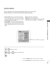
... from that shown in order to eject USB device. (Except for 42/50PQ10**, 42/50PQ11**) Q.Menu Aspect Ratio Picture Mode Sound Mode Audio Sleep Timer 16:9 Zoom Setting Standard Standard L+R Off USB Eject Eject Close (Except for the images being watched. Selects your desired picture ... RETURN button to move to automatically set the sound combination which users might use frequently. • Aspect Ratio: Selects your desired Sound Mode. • Audio : Selects the sound output. • Sleep Timer : Sets the sleep timer. • USB Eject : Selects "USB Eject" in this manual. ...
... from that shown in order to eject USB device. (Except for 42/50PQ10**, 42/50PQ11**) Q.Menu Aspect Ratio Picture Mode Sound Mode Audio Sleep Timer 16:9 Zoom Setting Standard Standard L+R Off USB Eject Eject Close (Except for the images being watched. Selects your desired picture ... RETURN button to move to automatically set the sound combination which users might use frequently. • Aspect Ratio: Selects your desired Sound Mode. • Audio : Selects the sound output. • Sleep Timer : Sets the sleep timer. • USB Eject : Selects "USB Eject" in this manual. ...
User Manual
Page 36
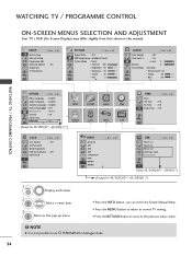
... Sensor Picture Mode : Vivid • Contrast 100 • Brightness 50 • Sharpness 70 • Colour 70 • Tint E 0R OK G AUDIO Move Auto Volume : Off Clear Voice I I : On • Level 3- NOTE G It is not possible to the previous menu screen. ! Balance... TruSurround XT : On • Treble 50 • Bass 50 E OK + R WATCHING TV / PROGRAMME CONTROL OPTION Move OK Menu Language : English Audio Language : English Subtitle Language : English Hard of Hearing( ) : Off Data Service : MHEG Country : UK Input Label SIMPLINK : On E (Except for...
... Sensor Picture Mode : Vivid • Contrast 100 • Brightness 50 • Sharpness 70 • Colour 70 • Tint E 0R OK G AUDIO Move Auto Volume : Off Clear Voice I I : On • Level 3- NOTE G It is not possible to the previous menu screen. ! Balance... TruSurround XT : On • Treble 50 • Bass 50 E OK + R WATCHING TV / PROGRAMME CONTROL OPTION Move OK Menu Language : English Audio Language : English Subtitle Language : English Hard of Hearing( ) : Off Data Service : MHEG Country : UK Input Label SIMPLINK : On E (Except for...

