Owners Manual
Page 6
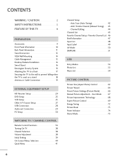
... 20 DVD Setup 23 VCR Setup 25 Other A/V Source Setup 27 USB Connection 28 Audio out Connection 29 PC Setup 30 WATCHING TV / CHANNEL CONTROL Remote Control Functions 36 Turning On TV 38 Channel Selection 38 Volume Adjustment 38 Initial Setting 39 On-Screen Menus Selection 40 Quick Menu 41 6 Channel Setup... Brief Information 47 Input List 48 Input Label 49 AV Mode 50 SIMPLINK 51 USB Entry Modes 54 Photo List 55 Music List 59 PICTURE CONTROL Picture Size (Aspect Ratio) Control 62 Picture Wizard 64 Preset Picture Settings (Picture Mode 66 Manual Picture Adjustment -
... 20 DVD Setup 23 VCR Setup 25 Other A/V Source Setup 27 USB Connection 28 Audio out Connection 29 PC Setup 30 WATCHING TV / CHANNEL CONTROL Remote Control Functions 36 Turning On TV 38 Channel Selection 38 Volume Adjustment 38 Initial Setting 39 On-Screen Menus Selection 40 Quick Menu 41 6 Channel Setup... Brief Information 47 Input List 48 Input Label 49 AV Mode 50 SIMPLINK 51 USB Entry Modes 54 Photo List 55 Music List 59 PICTURE CONTROL Picture Size (Aspect Ratio) Control 62 Picture Wizard 64 Preset Picture Settings (Picture Mode 66 Manual Picture Adjustment -

Owners Manual
Page 7
... Broadcasting System Captions 88 - Auto Clock Setup 90 Manual Clock Setup 91 Auto On/Off Time Setting 92 Sleep Timer Setting 93 PARENTAL CONTROL / RATINGS Set Password & Lock System 94 Channel Blocking 97 Movie & TV Rating 98 Downloadable Rating 101 External Input Blocking 102 Key... Lock 103 APPENDIX Troubleshooting 104 Maintenance 106 Product Specifications 107 IR Codes 108 External Control Through RS-232C 110 Open Source License 116 7 SOUND & LANGUAGE CONTROL Auto Volume Leveler (Auto Volume 76 Clear Voice II 77 Preset Sound Setting (Sound Mode 78 ...
... Broadcasting System Captions 88 - Auto Clock Setup 90 Manual Clock Setup 91 Auto On/Off Time Setting 92 Sleep Timer Setting 93 PARENTAL CONTROL / RATINGS Set Password & Lock System 94 Channel Blocking 97 Movie & TV Rating 98 Downloadable Rating 101 External Input Blocking 102 Key... Lock 103 APPENDIX Troubleshooting 104 Maintenance 106 Product Specifications 107 IR Codes 108 External Control Through RS-232C 110 Open Source License 116 7 SOUND & LANGUAGE CONTROL Auto Volume Leveler (Auto Volume 76 Clear Voice II 77 Preset Sound Setting (Sound Mode 78 ...
Owners Manual
Page 9
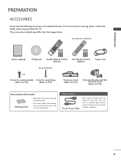
...9 FLASHBK RETURN VOL CH OK CH VOL 2 3 6 BED1 BED2 1.5V 1.5V Owner's Manual CD Manual Installer Remote Control, User Remote Control, Batteries Batteries Power Cord (Except 47LH300C) x 4 Screws for stand assembly Screw for stand fixing (Refer to P.12)... (Refer to P.17) Protection Cover (Refer to P.13) Protective Bracket and Bolt for Power Cord (Refer to maintain standards compliance. 9 Option Extras D-sub 15 pin Cable When using the VGA...
...9 FLASHBK RETURN VOL CH OK CH VOL 2 3 6 BED1 BED2 1.5V 1.5V Owner's Manual CD Manual Installer Remote Control, User Remote Control, Batteries Batteries Power Cord (Except 47LH300C) x 4 Screws for stand assembly Screw for stand fixing (Refer to P.12)... (Refer to P.17) Protection Cover (Refer to P.13) Protective Bracket and Bolt for Power Cord (Refer to maintain standards compliance. 9 Option Extras D-sub 15 pin Cable When using the VGA...
Owners Manual
Page 10
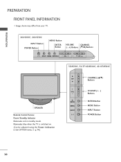
... INPUT Button POWER Button MENU Button ENTER Button VOLUME CHANNEL (-, +) Buttons (E,D) Buttons INPUT MENU ENTER VOL CH 32LH210C, 32/37/42LH200C, 42/47LH300C SPEAKER Remote Control Sensor, Power/Standby Indicator Illuminates red in the OPTION menu. Illuminates blue when the TV is switched on. (Can be adjusted using the Power Indicator...
... INPUT Button POWER Button MENU Button ENTER Button VOLUME CHANNEL (-, +) Buttons (E,D) Buttons INPUT MENU ENTER VOL CH 32LH210C, 32/37/42LH200C, 42/47LH300C SPEAKER Remote Control Sensor, Power/Standby Indicator Illuminates red in the OPTION menu. Illuminates blue when the TV is switched on. (Can be adjusted using the Power Indicator...
Owners Manual
Page 11
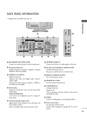
.... Supports HD. Supports standard definition video only (480i). 7 RS-232C IN (CONTROL & SERVICE) PORT Used by third party devices. Accepts DVI video using an adapter or HDMI to operate the TV on DC power. 11 Uses a D-sub 15 pin cable (VGA cable). This port is used for external speaker jack. 10 COMPONENT IN..., and blue cable for video & red and white for audio. 11 USB IN Used for viewing photos and listening to this port doesn't work. 8 REMOTE CONTROL IN PORT For a wired remote control. 9 SPEAKER OUT PORT Used for Service or Hotel mode. 3 HDMI/DVI IN, HDMI IN Digital Connection.
.... Supports HD. Supports standard definition video only (480i). 7 RS-232C IN (CONTROL & SERVICE) PORT Used by third party devices. Accepts DVI video using an adapter or HDMI to operate the TV on DC power. 11 Uses a D-sub 15 pin cable (VGA cable). This port is used for external speaker jack. 10 COMPONENT IN..., and blue cable for video & red and white for audio. 11 USB IN Used for viewing photos and listening to this port doesn't work. 8 REMOTE CONTROL IN PORT For a wired remote control. 9 SPEAKER OUT PORT Used for Service or Hotel mode. 3 HDMI/DVI IN, HDMI IN Digital Connection.
Owners Manual
Page 20
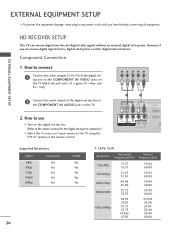
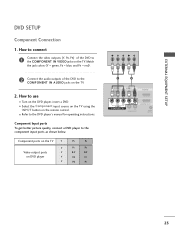
... if you have finished connecting all equipment. EXTERNAL EQUIPMENT SETUP I Select the Component input source on the TV using the INPUT button on the remote control. 1 2 RJP AV IN 1 VIDEO AUDIO 2 L(MONO) R 1 VIDEO COMPONENT IN L AUDIO R L R SPEAKER OUT /DVI IN REMO... CONTRO Supported Resolutions Signal Component 480i Yes 480p Yes 720p Yes 1080i Yes 1080p Yes HDMI No Yes Yes Yes Yes 20 Y, CB/PB, CR/PR Resolution Horizontal Vertical Frequency(KHz) Frequency(Hz) 720x480i 720x480p 1280x720p 1920x1080i 1920x1080p ...
... if you have finished connecting all equipment. EXTERNAL EQUIPMENT SETUP I Select the Component input source on the TV using the INPUT button on the remote control. 1 2 RJP AV IN 1 VIDEO AUDIO 2 L(MONO) R 1 VIDEO COMPONENT IN L AUDIO R L R SPEAKER OUT /DVI IN REMO... CONTRO Supported Resolutions Signal Component 480i Yes 480p Yes 720p Yes 1080i Yes 1080p Yes HDMI No Yes Yes Yes Yes 20 Y, CB/PB, CR/PR Resolution Horizontal Vertical Frequency(KHz) Frequency(Hz) 720x480i 720x480p 1280x720p 1920x1080i 1920x1080p ...
Owners Manual
Page 21
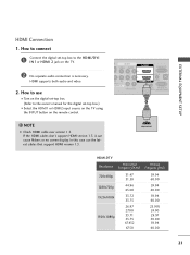
...1 VIDEO AUDIO 2 L(MONO) R 1 DEO ONENT IN L AUDIO R L R SPEAKER OUT RGB IN (PC) AUDIO IN O /DVI IN (RGB/DVI) REMOTE RS-232C IN CONTROL IN (CONTROL&SERVICE) 1 HDMI OUTPUT HDMI-DTV Resolution Horizontal Vertical Frequency(KHz) Frequency(Hz) 720x480p 1280x720p 1920x1080i 1920x1080p 31.47 31.50 44.96 45.00 33.72 33.75... set-top box. (Refer to the owner's manual for the digital set -top box to connect 1 Connect the digital set -top box.) I N 1or HDMI 2 jack on the remote control. ! EXTERNAL EQUIPMENT SETUP HDMI Connection 1. HDMI supports both audio and video. 2.
...1 VIDEO AUDIO 2 L(MONO) R 1 DEO ONENT IN L AUDIO R L R SPEAKER OUT RGB IN (PC) AUDIO IN O /DVI IN (RGB/DVI) REMOTE RS-232C IN CONTROL IN (CONTROL&SERVICE) 1 HDMI OUTPUT HDMI-DTV Resolution Horizontal Vertical Frequency(KHz) Frequency(Hz) 720x480p 1280x720p 1920x1080i 1920x1080p 31.47 31.50 44.96 45.00 33.72 33.75... set-top box. (Refer to the owner's manual for the digital set -top box to connect 1 Connect the digital set -top box.) I N 1or HDMI 2 jack on the remote control. ! EXTERNAL EQUIPMENT SETUP HDMI Connection 1. HDMI supports both audio and video. 2.
Owners Manual
Page 22
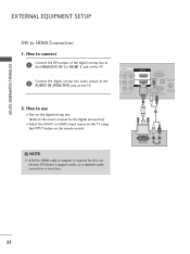
... (RGB/DVI) OPTICAL DIGIT AUDIO OUT REMOTE RS-232C IN ACNATBELNENIAN CONTROL IN (CONTROL&SERVICE) 1 2 ! DVI OUTPUT L R AUDIO 22 How to connect 1 Connect the DVI output of the digital set-top box to the HDMI/DVI IN 1or HDMI 2 jack on the TV. 2 Connect the digital set-top box...the owner's manual for this connection. NOTE G A DVI to HDMI Connection 1. DVI doesn't support audio, so a separate audio connection is required for the digital set -top box. (Refer to the AUDIO IN (RGB/DVI) jack on the remote control. EXTERNAL EQUIPMENT SETUP EXTERNAL EQUIPMENT SETUP DVI to...
... (RGB/DVI) OPTICAL DIGIT AUDIO OUT REMOTE RS-232C IN ACNATBELNENIAN CONTROL IN (CONTROL&SERVICE) 1 2 ! DVI OUTPUT L R AUDIO 22 How to connect 1 Connect the DVI output of the digital set-top box to the HDMI/DVI IN 1or HDMI 2 jack on the TV. 2 Connect the digital set-top box...the owner's manual for this connection. NOTE G A DVI to HDMI Connection 1. DVI doesn't support audio, so a separate audio connection is required for the digital set -top box. (Refer to the AUDIO IN (RGB/DVI) jack on the remote control. EXTERNAL EQUIPMENT SETUP EXTERNAL EQUIPMENT SETUP DVI to...
Owners Manual
Page 23
... ports on the TV Y Y Video output ports Y on the TV. I Select the Component input source on the TV using the INPUT button on the remote control. How to connect 1 Connect the video outputs (Y, PB, PR) of the DVD to use I Turn on the TV. 2. EXTERNAL EQUIPMENT SETUP DVD SETUP Component Connection...
... ports on the TV Y Y Video output ports Y on the TV. I Select the Component input source on the TV using the INPUT button on the remote control. How to connect 1 Connect the video outputs (Y, PB, PR) of the DVD to use I Turn on the TV. 2. EXTERNAL EQUIPMENT SETUP DVD SETUP Component Connection...
Owners Manual
Page 24
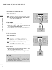
... on the TV. 2 No separated audio connection is necessary. How to use the latest cables that support HDMI version 1.3. NOTE G Check HDMI cable over version 1.3. How to the DVD player's manual for operating instructions. I Turn on the remote control. HDMI OUTPUT 24 HDMI Connection 1. EXTERNAL EQUIPMENT SETUP EXTERNAL EQUIPMENT SETUP Composite (RCA) Connection 1. If the...
... on the TV. 2 No separated audio connection is necessary. How to use the latest cables that support HDMI version 1.3. NOTE G Check HDMI cable over version 1.3. How to the DVD player's manual for operating instructions. I Turn on the remote control. HDMI OUTPUT 24 HDMI Connection 1. EXTERNAL EQUIPMENT SETUP EXTERNAL EQUIPMENT SETUP Composite (RCA) Connection 1. If the...
Owners Manual
Page 25
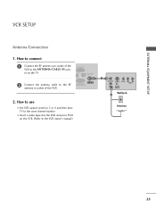
... VIDEO L R AUDIO ANT IN OUTPUT SWITCH Wall Jack 2 Antenna 25 RGB IN (PC) DIO IN GB/DVI) OPTICAL DIGITAL AUDIO OUT RS-232C IN ACNATBELNENIAN/ CONTROL&SERVICE) 2.
... VIDEO L R AUDIO ANT IN OUTPUT SWITCH Wall Jack 2 Antenna 25 RGB IN (PC) DIO IN GB/DVI) OPTICAL DIGITAL AUDIO OUT RS-232C IN ACNATBELNENIAN/ CONTROL&SERVICE) 2.

Owners Manual
Page 26
... PLAY on the VCR. (Refer to the VCR owner's manual.) I Select the A V 1 or A V 2 input source on the TV using the INPUT button on the remote control. ! PREPARATION PREPARATION Composite (RCA) Connection 1.
... PLAY on the VCR. (Refer to the VCR owner's manual.) I Select the A V 1 or A V 2 input source on the TV using the INPUT button on the remote control. ! PREPARATION PREPARATION Composite (RCA) Connection 1.

Owners Manual
Page 27
Match the jack colors. (Video = yellow, Audio Left = white, and Audio Right = red) 2. USB IN Camcorder Video Game Set VIDEO L R 1 VIDEO L/MONO AUDIO R AV IN 2 27 PREPARATION OTHER A/V SOURCE SETUP 1. How to use I Operate the corresponding external equipment. How to connect 1 Connect the AUDIO/VIDEO jacks between TV and external equipment. I Select the A V 1 or A V 2 input source on the TV using the INPUT button on the remote control.
Match the jack colors. (Video = yellow, Audio Left = white, and Audio Right = red) 2. USB IN Camcorder Video Game Set VIDEO L R 1 VIDEO L/MONO AUDIO R AV IN 2 27 PREPARATION OTHER A/V SOURCE SETUP 1. How to use I Operate the corresponding external equipment. How to connect 1 Connect the AUDIO/VIDEO jacks between TV and external equipment. I Select the A V 1 or A V 2 input source on the TV using the INPUT button on the remote control.
Owners Manual
Page 29
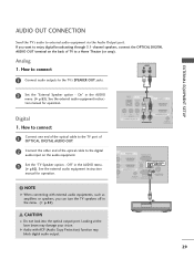
...in the menu. (G p.82) 1 RJP AV IN 1 VIDEO AUDIO 2 L(MONO) R 1 VIDEO COMPONENT IN L AUDIO R L R SPEAKER OUT AU (RG /DVI IN REMOTE CONTROL IN (C O 2 R 1 R R OUT RGB IN (PC) AUDIO IN OPTICAL DIGITAL AUDIO OUT /DVI IN (RGB/DVI) 1 REMOTE ANTENNA/ RS-232C IN CABLE IN... CONTROL IN (CONTROL&SERVICE) 2 CAUTION G Do not look into the optical output port. Digital 1. See the external audio equipment instruction manual for operation. See the external audio ...
...in the menu. (G p.82) 1 RJP AV IN 1 VIDEO AUDIO 2 L(MONO) R 1 VIDEO COMPONENT IN L AUDIO R L R SPEAKER OUT AU (RG /DVI IN REMOTE CONTROL IN (C O 2 R 1 R R OUT RGB IN (PC) AUDIO IN OPTICAL DIGITAL AUDIO OUT /DVI IN (RGB/DVI) 1 REMOTE ANTENNA/ RS-232C IN CABLE IN... CONTROL IN (CONTROL&SERVICE) 2 CAUTION G Do not look into the optical output port. Digital 1. See the external audio equipment instruction manual for operation. See the external audio ...
Owners Manual
Page 30
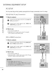
... This TV provides Plug and Play capability, meaning that support HDMI version 1.3. 30 AUDIO RGB OUTPUT AV IN 1 VIDEO AUDIO 2 L(MONO) R 1 EO ENT IN L AUDIO R L R SPEAKER OUT RGB IN (PC) AUDIO IN /DVI IN (RGB/DVI) OPTI AU A REMOTE RS-232C IN C CONTROL IN (CONTROL&SERVICE) 1 2 DVI OUTPUT AUDIO VGA (D-Sub 15 pin) Connection 1.
... This TV provides Plug and Play capability, meaning that support HDMI version 1.3. 30 AUDIO RGB OUTPUT AV IN 1 VIDEO AUDIO 2 L(MONO) R 1 EO ENT IN L AUDIO R L R SPEAKER OUT RGB IN (PC) AUDIO IN /DVI IN (RGB/DVI) OPTI AU A REMOTE RS-232C IN C CONTROL IN (CONTROL&SERVICE) 1 2 DVI OUTPUT AUDIO VGA (D-Sub 15 pin) Connection 1.
Owners Manual
Page 32
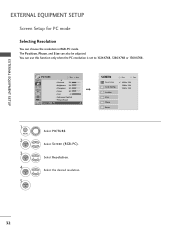
... resolution in RGB-PC mode. PICTURE Move Enter E • Contrast 50 • Brightness 50 • Sharpness 50 • Color 50 • Tint 0R G • Advanced Control • Picture Reset Screen (RGB-PC) SCREEN Resolution Auto Config. EXTERNAL EQUIPMENT SETUP EXTERNAL EQUIPMENT SETUP Screen Setup for PC mode Selecting Resolution You can...
... resolution in RGB-PC mode. PICTURE Move Enter E • Contrast 50 • Brightness 50 • Sharpness 50 • Color 50 • Tint 0R G • Advanced Control • Picture Reset Screen (RGB-PC) SCREEN Resolution Auto Config. EXTERNAL EQUIPMENT SETUP EXTERNAL EQUIPMENT SETUP Screen Setup for PC mode Selecting Resolution You can...
Owners Manual
Page 33
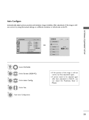
... Select Y e s. 5 ENTER Start Auto Configuration. PICTURE Move Enter E • Contrast 50 • Brightness 50 • Sharpness 50 • Color 50 • Tint 0R G • Advanced Control • Picture Reset Screen (RGB-PC) 1 MENU 2 ENTER 3 ENTER Select PICTURE. Position Size Phase Reset Move Prev. SCREEN Resolution Auto Config.
... Select Y e s. 5 ENTER Start Auto Configuration. PICTURE Move Enter E • Contrast 50 • Brightness 50 • Sharpness 50 • Color 50 • Tint 0R G • Advanced Control • Picture Reset Screen (RGB-PC) 1 MENU 2 ENTER 3 ENTER Select PICTURE. Position Size Phase Reset Move Prev. SCREEN Resolution Auto Config.
Owners Manual
Page 34
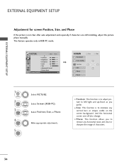
... screen size will also change. PICTURE Move Enter E • Contrast 50 • Brightness 50 • Sharpness 50 • Color 50 • Tint 0R G • Advanced Control • Picture Reset Screen (RGB-PC) SCREEN Resolution Auto Config. Select Position, S i z e, or Phase. Position Size Phase Reset Move Prev.
... screen size will also change. PICTURE Move Enter E • Contrast 50 • Brightness 50 • Sharpness 50 • Color 50 • Tint 0R G • Advanced Control • Picture Reset Screen (RGB-PC) SCREEN Resolution Auto Config. Select Position, S i z e, or Phase. Position Size Phase Reset Move Prev.
Owners Manual
Page 35
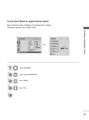
This feature operates only in RGB-PC mode. Select Reset. Select Y e s. 35 To Set Yes No 1 MENU 2 ENTER 3 ENTER 4 ENTER 5 ENTER Select PICTURE. Select Screen (RGB-PC). EXTERNAL EQUIPMENT SETUP Screen Reset (Reset to original factory values) Returns Position, S i z e, and Phase to the default factory settings. Position Size Phase Reset Move Prev. PICTURE Move Enter E • Contrast 50 • Brightness 50 • Sharpness 50 • Color 50 • Tint 0R G • Advanced Control • Picture Reset Screen (RGB-PC) SCREEN Resolution Auto Config.
This feature operates only in RGB-PC mode. Select Reset. Select Y e s. 35 To Set Yes No 1 MENU 2 ENTER 3 ENTER 4 ENTER 5 ENTER Select PICTURE. Select Screen (RGB-PC). EXTERNAL EQUIPMENT SETUP Screen Reset (Reset to original factory values) Returns Position, S i z e, and Phase to the default factory settings. Position Size Phase Reset Move Prev. PICTURE Move Enter E • Contrast 50 • Brightness 50 • Sharpness 50 • Color 50 • Tint 0R G • Advanced Control • Picture Reset Screen (RGB-PC) SCREEN Resolution Auto Config.
Owners Manual
Page 36
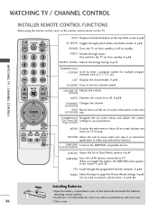
... Navigates the on from standby or off . G p.51-53 FAV Scroll through inputs. UP/DOWN PAGE Moves from standby. ControSlIMbuPtLtIoNnKs Controls the SIMPLINK compatible devices. G p.41 SIMPLINK See a list of AV devices connected to the next UP/DOWN one full set of... program channels such as 2-1, 2-2, etc. G p.48 ENERGY SAVING Adjusts the Energy Saving. WATCHING TV / CHANNEL CONTROL WATCHING TV / CHANNEL CONTROL INSTALLER REMOTE CONTROL FUNCTIONS When using the remote control, aim it at the top of the screen. G p.45 FLASHBK Tunes to TV viewing. I Install two 1....
... Navigates the on from standby or off . G p.51-53 FAV Scroll through inputs. UP/DOWN PAGE Moves from standby. ControSlIMbuPtLtIoNnKs Controls the SIMPLINK compatible devices. G p.41 SIMPLINK See a list of AV devices connected to the next UP/DOWN one full set of... program channels such as 2-1, 2-2, etc. G p.48 ENERGY SAVING Adjusts the Energy Saving. WATCHING TV / CHANNEL CONTROL WATCHING TV / CHANNEL CONTROL INSTALLER REMOTE CONTROL FUNCTIONS When using the remote control, aim it at the top of the screen. G p.45 FLASHBK Tunes to TV viewing. I Install two 1....


