
User Manual
Page 1
...: This product qualifies for future reference. LCD TV OWNER'S MANUAL 32LH240H 32LH250H 37LH250H 42LH250H 32LH255H 37LH255H 42LH255H 37LH260H 42LH260H 37LH265H please read this information to quality for ENERGY STAR. 1-800-243-0000 USA, Consumer User 1-888-865-3026 USA, Commercial User 1-888-542-2623 CANADA LG Customer Information Center P/NO : SAC34026004 (0912-REV00...
...: This product qualifies for future reference. LCD TV OWNER'S MANUAL 32LH240H 32LH250H 37LH250H 42LH250H 32LH255H 37LH255H 42LH255H 37LH260H 42LH260H 37LH265H please read this information to quality for ENERGY STAR. 1-800-243-0000 USA, Consumer User 1-888-865-3026 USA, Commercial User 1-888-542-2623 CANADA LG Customer Information Center P/NO : SAC34026004 (0912-REV00...
User Manual
Page 3
...not occur in construction of the National Electric Code (U.S.A.). Consult the dealer or an experienced radio/TV technician for compliance could void the user's authority to rain or moisture. Any changes or modifications in a particular ...installation. NOTE TO CABLE/TV INSTALLER This reminder is subject to Part 15 of important operating and maintenance (servicing) instructions in a residential installation... the interference by turning the equipment off and on a circuit different from LG Electronics.
...not occur in construction of the National Electric Code (U.S.A.). Consult the dealer or an experienced radio/TV technician for compliance could void the user's authority to rain or moisture. Any changes or modifications in a particular ...installation. NOTE TO CABLE/TV INSTALLER This reminder is subject to Part 15 of important operating and maintenance (servicing) instructions in a residential installation... the interference by turning the equipment off and on a circuit different from LG Electronics.

User Manual
Page 5
...appearance indicates damage or deterioration, unplug it to be certain. Do not use of these conditions could result in . Do not touch the TV with something. 14 CAUTION concerning the Power Cord : It is recommend that is the disconnecting device. Do not overload wall outlets. Be ...three-prong grounded AC plug must remain readily operable. 3 Do not install this could result in a door, or walked upon a dedicated circuit; a TV with liquids, such as this product near flammable objects such as being twisted, kinked, pinched, closed in electric shock or fire. Protect the power ...
...appearance indicates damage or deterioration, unplug it to be certain. Do not use of these conditions could result in . Do not touch the TV with something. 14 CAUTION concerning the Power Cord : It is recommend that is the disconnecting device. Do not overload wall outlets. Be ...three-prong grounded AC plug must remain readily operable. 3 Do not install this could result in a door, or walked upon a dedicated circuit; a TV with liquids, such as this product near flammable objects such as being twisted, kinked, pinched, closed in electric shock or fire. Protect the power ...

User Manual
Page 6
...in the U.S.A. This is normal, there is installed, follow the precautions below. However, they have been removed. ON DISPOSAL (Only Hg lamp used LCD TV) The fluorescent lamp used in this product contains a small amount of the National Electrical Code (NEC) in a confined space such as electric shock may... the grounding electrode. It may occur. Do not cover the product with cloth or other odors coming from direct sunlight. 27 For LCD TV If the TV feels cold to the regulations of time. Do not install in Wire Antenna Discharge Unit (NEC Section 810-20) Grounding Conductors (NEC Section...
...in the U.S.A. This is normal, there is installed, follow the precautions below. However, they have been removed. ON DISPOSAL (Only Hg lamp used LCD TV) The fluorescent lamp used in this product contains a small amount of the National Electrical Code (NEC) in a confined space such as electric shock may... the grounding electrode. It may occur. Do not cover the product with cloth or other odors coming from direct sunlight. 27 For LCD TV If the TV feels cold to the regulations of time. Do not install in Wire Antenna Discharge Unit (NEC Section 810-20) Grounding Conductors (NEC Section...
User Manual
Page 7
...55 Manual Picture Adjustment - Black (Darkness) Level 58 Advanced Control - SRS TruSurround XT 65 Clear Voice II 66 Balance 67 TV Speakers On/Off Setup 68 Audio Reset 69 Stereo/SAP Broadcast Setup 70 Audio Language 71 On-Screen Menus Language Selection 72 ...Caption Mode - User Mode 56 Picture Improvement Technology 57 Advanced Control - WARNING / CAUTION 1 SAFETY INSTRUCTIONS 2 FEATURES OF THIS TV 7 PREPARATION Accessories 8 Front Panel Information 9 Back Panel Information 10 Stand Instruction 12 VESA Wall Mounting 14 Cable Management 15 Desktop Pedestal ...
...55 Manual Picture Adjustment - Black (Darkness) Level 58 Advanced Control - SRS TruSurround XT 65 Clear Voice II 66 Balance 67 TV Speakers On/Off Setup 68 Audio Reset 69 Stereo/SAP Broadcast Setup 70 Audio Language 71 On-Screen Menus Language Selection 72 ...Caption Mode - User Mode 56 Picture Improvement Technology 57 Advanced Control - WARNING / CAUTION 1 SAFETY INSTRUCTIONS 2 FEATURES OF THIS TV 7 PREPARATION Accessories 8 Front Panel Information 9 Back Panel Information 10 Stand Instruction 12 VESA Wall Mounting 14 Cable Management 15 Desktop Pedestal ...
User Manual
Page 9
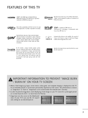
... digital television broadcast and playback system composed of human voice frequency range to prevent image burn, avoid displaying a fixed image on your TV through USB 2.0 ('videos' dependent on the letterboxed areas of the film for an extended period, it can also occur on model).... IMPORTANT INFORMATION TO PREVENT "IMAGE BURN / BURN-IN" ON YOUR TV SCREEN ■ When a fixed image (e.g. Image burn is displayed on the TV for a more pixels, 16:9 aspect-ratio screens, and AC3 digital audio. LG TV include a unique invisible speaker system, tuned by increasing the "sweet spot...
... digital television broadcast and playback system composed of human voice frequency range to prevent image burn, avoid displaying a fixed image on your TV through USB 2.0 ('videos' dependent on the letterboxed areas of the film for an extended period, it can also occur on model).... IMPORTANT INFORMATION TO PREVENT "IMAGE BURN / BURN-IN" ON YOUR TV SCREEN ■ When a fixed image (e.g. Image burn is displayed on the TV for a more pixels, 16:9 aspect-ratio screens, and AC3 digital audio. LG TV include a unique invisible speaker system, tuned by increasing the "sweet spot...

User Manual
Page 10
...Protection Cover (Refer to P.13) Protective Bracket and Bolt for Power Cord (This feature is missing, please contact the dealer where you purchased the TV. PREPERATION ACCESSORIES Ensure that the following accessories are included with ferrite cores to P.15) 8 Excessive pressure may differ from the images be7lo8 5w6.3 ...15 pin Cable When using the VGA (D-sub 15 pin cable) PC connection, the user must use shielded signal interface cables with your TV. If an accessory is not available for all models Polishing Cloth * Wipe spots on the exterior only with the polishing cloth. * ...
...Protection Cover (Refer to P.13) Protective Bracket and Bolt for Power Cord (This feature is missing, please contact the dealer where you purchased the TV. PREPERATION ACCESSORIES Ensure that the following accessories are included with ferrite cores to P.15) 8 Excessive pressure may differ from the images be7lo8 5w6.3 ...15 pin Cable When using the VGA (D-sub 15 pin cable) PC connection, the user must use shielded signal interface cables with your TV. If an accessory is not available for all models Polishing Cloth * Wipe spots on the exterior only with the polishing cloth. * ...
User Manual
Page 11
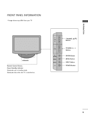
PREPARATION FRONT PANEL INFORMATION ■ Image shown may differ from your TV. CH VOL ENTER MENU INPUT CHANNEL (D,E) Buttons VOLUME (+, -) Buttons ENTER Button MENU Button INPUT Button POWER Button 9 SPEAKER Remote Control Sensor, Power/Standby Indicator Illuminates red in standby mode. Illuminates blue when the TV is switched on.
PREPARATION FRONT PANEL INFORMATION ■ Image shown may differ from your TV. CH VOL ENTER MENU INPUT CHANNEL (D,E) Buttons VOLUME (+, -) Buttons ENTER Button MENU Button INPUT Button POWER Button 9 SPEAKER Remote Control Sensor, Power/Standby Indicator Illuminates red in standby mode. Illuminates blue when the TV is switched on.
User Manual
Page 13
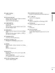
...; Connect to external speaker input. 6 REMOTE CONTROL OUT IR output for controlling an auxiliary device. 10 RJP (REMOTE JACK PACK PORT) Connect to operate the TV on DC power. 7 UPDATE Enables/disables software downloads and debug mode. Caution: Never attempt to remote jack pack control output port. 11... TV - Uses a D-sub 15 pin cable (VGA cable). LINK CFG Used for FTG Configuration 12 USB IN Used for audio. 4 HDMI/DVI IN Digital Connection. RESET ...
...; Connect to external speaker input. 6 REMOTE CONTROL OUT IR output for controlling an auxiliary device. 10 RJP (REMOTE JACK PACK PORT) Connect to operate the TV on DC power. 7 UPDATE Enables/disables software downloads and debug mode. Caution: Never attempt to remote jack pack control output port. 11... TV - Uses a D-sub 15 pin cable (VGA cable). LINK CFG Used for FTG Configuration 12 USB IN Used for audio. 4 HDMI/DVI IN Digital Connection. RESET ...
User Manual
Page 14
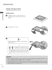
... setting the cable management in figure 2 above, you can hear some disturbing noise which is fully tightened (If not tightened fully, the TV can tilt forward after the product installation). Tighten the two Torx plus star head screws (provided as parts of the... assembling the stand as in the right position. 12 INSTALLATION 1 Carefully place the TV screen side down on a cushioned surface to secure the TV. PREPARATION PREPARATION STAND INSTRUCTION ■ Image shown may differ from damage. 2 Assemble the TV as shown. 3 x 4 Tighten the stand with a star head driver bit (not provided...
... setting the cable management in figure 2 above, you can hear some disturbing noise which is fully tightened (If not tightened fully, the TV can tilt forward after the product installation). Tighten the two Torx plus star head screws (provided as parts of the... assembling the stand as in the right position. 12 INSTALLATION 1 Carefully place the TV screen side down on a cushioned surface to secure the TV. PREPARATION PREPARATION STAND INSTRUCTION ■ Image shown may differ from damage. 2 Assemble the TV as shown. 3 x 4 Tighten the stand with a star head driver bit (not provided...
User Manual
Page 15
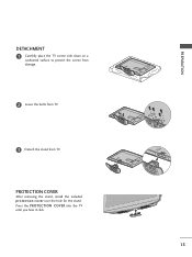
Press the PROTECTION COVER into the TV until you hear it click. 13 PROTECTION COVER After removing the stand, install the included protection cover over the hole for the stand. PREPARATION DETACHMENT 1 Carefully place the TV screen side down on a cushioned surface to protect the screen from damage. 2 Loose the bolts from TV. 3 Detach the stand from TV.
Press the PROTECTION COVER into the TV until you hear it click. 13 PROTECTION COVER After removing the stand, install the included protection cover over the hole for the stand. PREPARATION DETACHMENT 1 Carefully place the TV screen side down on a cushioned surface to protect the screen from damage. 2 Loose the bolts from TV. 3 Detach the stand from TV.
User Manual
Page 16
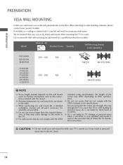
...non specified wall mount is not liable for assembly are shown in the table. Do not use an LG brand wall mount when mounting the TV to follow the TV installation instructions. LG is turned on the wall mount used or the consumer fails to a wall. G Do not ...B) A Standard Screw Quantity B Wall Mounting Bracket (sold separately) 32LH240H, 32LH250H, 200 * 100 M4 4 32LH255H 37LH250H, 37LH255H, 37LH260H, 37LH265H, 200 * 200 M6 4 42LH255H, 42LH260H, 42LH265H RW230 AW-47LG30M AW-47LG30M ! G Do not use screws longer then the standard dimension, as they may damage the...
...non specified wall mount is not liable for assembly are shown in the table. Do not use an LG brand wall mount when mounting the TV to follow the TV installation instructions. LG is turned on the wall mount used or the consumer fails to a wall. G Do not ...B) A Standard Screw Quantity B Wall Mounting Bracket (sold separately) 32LH240H, 32LH250H, 200 * 100 M4 4 32LH255H 37LH250H, 37LH255H, 37LH260H, 37LH265H, 200 * 200 M6 4 42LH255H, 42LH260H, 42LH265H RW230 AW-47LG30M AW-47LG30M ! G Do not use screws longer then the standard dimension, as they may damage the...
User Manual
Page 17
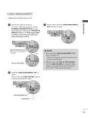
... product may differ from being removed by accident. 3 Put the cables inside the CABLE MANAGEMENT CLIP and snap it as shown. If your TV. 1 Connect the cables as necessary. G With some TVs, the PLUG IN TYPE HOLDER and the CABLE HOLDER are inserted into the hole provided on back of the... BRACKET/Screw or the Plug in type Holder. NOTE G Do not hold the CABLE MANAGEMENT CLIP when moving the TV. - PREPARATION CABLE MANAGEMENT ■ Image shown may be broken. If the TV is not available for all models.) Or PLUG IN TYPE HOLDER 2 Install the CABLE MANAGEMENT CLIP as shown and...
... product may differ from being removed by accident. 3 Put the cables inside the CABLE MANAGEMENT CLIP and snap it as shown. If your TV. 1 Connect the cables as necessary. G With some TVs, the PLUG IN TYPE HOLDER and the CABLE HOLDER are inserted into the hole provided on back of the... BRACKET/Screw or the Plug in type Holder. NOTE G Do not hold the CABLE MANAGEMENT CLIP when moving the TV. - PREPARATION CABLE MANAGEMENT ■ Image shown may be broken. If the TV is not available for all models.) Or PLUG IN TYPE HOLDER 2 Install the CABLE MANAGEMENT CLIP as shown and...
User Manual
Page 18
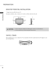
G Do not mount near or above any type of 4 inches on all four sides from your viewing position. 16 SWIVEL STAND After installing the TV, you can adjust the TV set manually to the left or right direction by following the clearance recommendations. For proper ventilation, allow a clearance of heat source. PREPARATION PREPARATION DESKTOP PEDESTAL INSTALLATION ■ Image shown may differ from the wall. 4 inches 4 inches 4 inches 4 inches CAUTION G Ensure adequate ventilation by 90 degrees to suit your TV.
G Do not mount near or above any type of 4 inches on all four sides from your viewing position. 16 SWIVEL STAND After installing the TV, you can adjust the TV set manually to the left or right direction by following the clearance recommendations. For proper ventilation, allow a clearance of heat source. PREPARATION PREPARATION DESKTOP PEDESTAL INSTALLATION ■ Image shown may differ from the wall. 4 inches 4 inches 4 inches 4 inches CAUTION G Ensure adequate ventilation by 90 degrees to suit your TV.
User Manual
Page 19
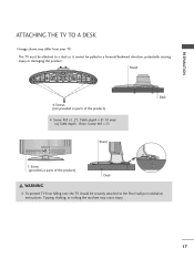
Tipping, shaking, or rocking the machine may differ from falling over, the TV should be securely attached to a desk so it cannot be attached to the floor/wall per installation instructions. Stand Desk 4-Screws (not provided as parts ...) G Screw: M5 x L (*L: Table depth + 8~10 mm) ex) Table depth: 15mm, Screw: M5 x 25 Stand 1-Screw (provided as parts of the product) Desk WARNING G To prevent TV from your TV. The TV must be pulled in a forward/backward direction, potentially causing injury or damaging the product. PREPARATION ATTACHING THE...
Tipping, shaking, or rocking the machine may differ from falling over, the TV should be securely attached to a desk so it cannot be attached to the floor/wall per installation instructions. Stand Desk 4-Screws (not provided as parts ...) G Screw: M5 x L (*L: Table depth + 8~10 mm) ex) Table depth: 15mm, Screw: M5 x 25 Stand 1-Screw (provided as parts of the product) Desk WARNING G To prevent TV from your TV. The TV must be pulled in a forward/backward direction, potentially causing injury or damaging the product. PREPARATION ATTACHING THE...

User Manual
Page 20
...enough and large enough to support the size and weight of the bracket that you set up the TV close to a wall so it becomes horizontal between the wall and the product. ! We recommend ...bolts position before inserting the eye-bolts, loosen the bolts. * Insert the eye-bolts or TV brackets/bolts and tighten them securely in a forward direction, potentially causing injury or damaging the product.... Caution: Please make sure that children don't climb on or hang from the TV. ■ Insert the eye-bolts (or TV brackets and bolts) to tighten the product to tie the rope so it cannot fall...
...enough and large enough to support the size and weight of the bracket that you set up the TV close to a wall so it becomes horizontal between the wall and the product. ! We recommend ...bolts position before inserting the eye-bolts, loosen the bolts. * Insert the eye-bolts or TV brackets/bolts and tighten them securely in a forward direction, potentially causing injury or damaging the product.... Caution: Please make sure that children don't climb on or hang from the TV. ■ Insert the eye-bolts (or TV brackets and bolts) to tighten the product to tie the rope so it cannot fall...

User Manual
Page 21
...optimum picture quality, adjust the direction if needed. Antenna (Analog or Digital) Wall Antenna Socket or Outdoor Antenna without a Cable Box Connection. Cable Cable TV Wall Jack RF Coaxial Wire (75 ohm) ANTENNA IN M.P.I . ANTENNA OR CABLE CONNECTION 1. Outdoor Antenna (VHF, UHF) RF Coaxial Wire (75...quality in a poor signal area, please purchase a signal amplifier and install properly. ■ If the antenna needs to be split for two TV's, install a 2-Way Signal Splitter. ■ If the antenna is not installed properly, contact your dealer for outdoor antenna) Copper Wire Be ...
...optimum picture quality, adjust the direction if needed. Antenna (Analog or Digital) Wall Antenna Socket or Outdoor Antenna without a Cable Box Connection. Cable Cable TV Wall Jack RF Coaxial Wire (75 ohm) ANTENNA IN M.P.I . ANTENNA OR CABLE CONNECTION 1. Outdoor Antenna (VHF, UHF) RF Coaxial Wire (75...quality in a poor signal area, please purchase a signal amplifier and install properly. ■ If the antenna needs to be split for two TV's, install a 2-Way Signal Splitter. ■ If the antenna is not installed properly, contact your dealer for outdoor antenna) Copper Wire Be ...

User Manual
Page 22
... 23.976 30.00 29.97 Component Connection 1. Match the jack colors (Y = green, PB = blue, and PR = red). How to use ■ Turn on the TV. 2. However, if you have finished connecting all equipment. ■ Image shown may differ from a digital set-top box or other digital external device, refer to... the owner's manual for the digital set -top box to the COMPONENT IN VIDEO jacks on the TV. Y PB PR L R 2 Connect the audio output of the digital settop box to the COMPONENT IN AUDIO jacks on the digital set -top box. HD ...
... 23.976 30.00 29.97 Component Connection 1. Match the jack colors (Y = green, PB = blue, and PR = red). How to use ■ Turn on the TV. 2. However, if you have finished connecting all equipment. ■ Image shown may differ from a digital set-top box or other digital external device, refer to... the owner's manual for the digital set -top box to the COMPONENT IN VIDEO jacks on the TV. Y PB PR L R 2 Connect the audio output of the digital settop box to the COMPONENT IN AUDIO jacks on the digital set -top box. HD ...
User Manual
Page 23
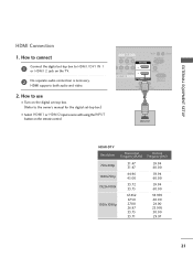
... set -top box to connect 1 Connect the digital set -top box.) ■ Select HDMI1 or HDMI2 input source with using the INPUT button on the TV. 2 No separate audio connection is necessary.
... set -top box to connect 1 Connect the digital set -top box.) ■ Select HDMI1 or HDMI2 input source with using the INPUT button on the TV. 2 No separate audio connection is necessary.

User Manual
Page 24
... digital set -top box. (Refer to HDMI cable or adapter is necessary. EXTERNAL EQUIPMENT SETUP EXTERNAL EQUIPMENT SETUP DVI to use ■ Turn on the TV. 2. GAME ONTROL AV IN 1 VIDEO AUDIO RGB IN (PC) L(MONO) R 2 AUDIO IN VIDEO L R AUDIO 1 COMPONENT IN (RGB/DVI) /DVI IN RS-232C IN (SERVICE ONLY...'s manual for this connection. How to connect 1 Connect the DVI output of the digital set-top box to the HDMI/DVI IN 1 jack on the TV. 2 Connect the audio output of the digital set-top box to the AUDIO IN (RGB/DVI) jack on the digital set -top box.) ■ Select...
... digital set -top box. (Refer to HDMI cable or adapter is necessary. EXTERNAL EQUIPMENT SETUP EXTERNAL EQUIPMENT SETUP DVI to use ■ Turn on the TV. 2. GAME ONTROL AV IN 1 VIDEO AUDIO RGB IN (PC) L(MONO) R 2 AUDIO IN VIDEO L R AUDIO 1 COMPONENT IN (RGB/DVI) /DVI IN RS-232C IN (SERVICE ONLY...'s manual for this connection. How to connect 1 Connect the DVI output of the digital set-top box to the HDMI/DVI IN 1 jack on the TV. 2 Connect the audio output of the digital set-top box to the AUDIO IN (RGB/DVI) jack on the digital set -top box.) ■ Select...


