Owner's Manual
Page 1
LCD TV MODELS 32LD400 42LD400 47LD500 P/NO :1947-1600-1050 www.lg.com OWNER'S MANUAL LCD TV Please read this manual carefully before operating your set and retain it for future reference.
LCD TV MODELS 32LD400 42LD400 47LD500 P/NO :1947-1600-1050 www.lg.com OWNER'S MANUAL LCD TV Please read this manual carefully before operating your set and retain it for future reference.

Owner's Manual
Page 2
... to the CAUTION grounding system of the FCC Rules. This device complies with the instructions, may cause undesired NOTE TO CABLE/TV INSTALLER operation (of electric shock to which can radiate radio frequency energy and, if not installed and used in construction of ...be determined by the party responsible for help. NO USER SERVICEABLE PARTS INSIDE. TV technician for compliance could void the user's authority to the point of important on a circuit different from LG Electronics. The code provides guidelines for proper grounding and, in particular, specifies ...
... to the CAUTION grounding system of the FCC Rules. This device complies with the instructions, may cause undesired NOTE TO CABLE/TV INSTALLER operation (of electric shock to which can radiate radio frequency energy and, if not installed and used in construction of ...be determined by the party responsible for help. NO USER SERVICEABLE PARTS INSIDE. TV technician for compliance could void the user's authority to the point of important on a circuit different from LG Electronics. The code provides guidelines for proper grounding and, in particular, specifies ...

Owner's Manual
Page 4
... overload wall outlets. Periodically examine the cord of these conditions could result in electric shock or fire. Pay particular attention to unplug the TV. 15 WARNING - Be sure do not expose this product to direct air conditioning. Overloaded wall outlets, loose or damaged wall outlets, ... FROM MAINS Mains plug is , a single outlet circuit which powers only that appliances be placed upon . Check the specification page of the TV. 13 Do not allow an impact shock or any objects to a three-prong grounded AC outlet). If grounding methods are dangerous . The...
... overload wall outlets. Periodically examine the cord of these conditions could result in electric shock or fire. Pay particular attention to unplug the TV. 15 WARNING - Be sure do not expose this product to direct air conditioning. Overloaded wall outlets, loose or damaged wall outlets, ... FROM MAINS Mains plug is , a single outlet circuit which powers only that appliances be placed upon . Check the specification page of the TV. 13 Do not allow an impact shock or any objects to a three-prong grounded AC outlet). If grounding methods are dangerous . The...

Owner's Manual
Page 5
... product is proper ventilation. Electrical circuit humming/ panel buzzing: A low level noise is a high technology product with respect to carry larger TVs. This generated sound does not affect the performance and reliability of the National Electrical Code (NEC) in contact with a soft cloth to ...Antenna Lead in a confined space such as a bookcase. Those dots are deactivated pixels and do not affect the performance and reliability of the TV. 29 Generated Sound "Cracking" noise: A cracking noise that occurs when watching or turning off , unplugged and all cables have been removed....
... product is proper ventilation. Electrical circuit humming/ panel buzzing: A low level noise is a high technology product with respect to carry larger TVs. This generated sound does not affect the performance and reliability of the National Electrical Code (NEC) in contact with a soft cloth to ...Antenna Lead in a confined space such as a bookcase. Those dots are deactivated pixels and do not affect the performance and reliability of the TV. 29 Generated Sound "Cracking" noise: A cracking noise that occurs when watching or turning off , unplugged and all cables have been removed....
Owner's Manual
Page 6
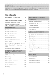
...45 Product Specifications 46 Open Source License 47 6 Contents WARNING / CAUTION 2 SAFETY INSTRUCTIONS........3 Important Safety Instructions 3 FEATURE OF THIS TV 7 PREPARATION Accessories 8 Front Panel Information 9 Back Panel Information 10 Stand Instructions 12 VESA Wall Mounting 13 Desktop Pedestal Installation 14 Swivel... Stand 14 Securing the TV to the Wall to the regulations of your local authority. Disposal of this product must be carried out in this product...
...45 Product Specifications 46 Open Source License 47 6 Contents WARNING / CAUTION 2 SAFETY INSTRUCTIONS........3 Important Safety Instructions 3 FEATURE OF THIS TV 7 PREPARATION Accessories 8 Front Panel Information 9 Back Panel Information 10 Stand Instructions 12 VESA Wall Mounting 13 Desktop Pedestal Installation 14 Swivel... Stand 14 Securing the TV to the Wall to the regulations of your local authority. Disposal of this product must be carried out in this product...

Owner's Manual
Page 7
... or "burn-in full 1920 x 1080p resolution for an extended period. 7 Highresolution digital television broadcast and playback system composed of your TV if you use the 4:3 aspect ratio setting for a more pixels, 16:9 aspectratio screens, and AC3 digital audio. IMPORTANT INFORMATION TO ...PREVENT "IMAGE BURN / BURN-IN" ON YOUR TV SCREEN a When a fixed image (e.g. Manufactured under the manufacturer's warranty. a Image burn can become permanently imprinted on the letter-boxed areas of...
... or "burn-in full 1920 x 1080p resolution for an extended period. 7 Highresolution digital television broadcast and playback system composed of your TV if you use the 4:3 aspect ratio setting for a more pixels, 16:9 aspectratio screens, and AC3 digital audio. IMPORTANT INFORMATION TO ...PREVENT "IMAGE BURN / BURN-IN" ON YOUR TV SCREEN a When a fixed image (e.g. Manufactured under the manufacturer's warranty. a Image burn can become permanently imprinted on the letter-boxed areas of...
Owner's Manual
Page 8
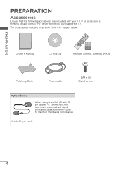
Owner's Manual CD Manual 1.5V 1.5V Remote Control, Batteries (AAA) Polishing Cloth Power cable (M4 x 6) Stand screws Option Extras When using the VGA (D-sub 15 pin cable) PC connection, the user must use shielded signal interface cables with your TV. If an accessory is missing, please contact the dealer where you purchased the TV. PREPARATION PREPARATION Accessories Ensure that the following accessories are included with ferrite cores to maintain standards compliance. The accessories included may differ from the images below. D-sub 15 pin cable 8
Owner's Manual CD Manual 1.5V 1.5V Remote Control, Batteries (AAA) Polishing Cloth Power cable (M4 x 6) Stand screws Option Extras When using the VGA (D-sub 15 pin cable) PC connection, the user must use shielded signal interface cables with your TV. If an accessory is missing, please contact the dealer where you purchased the TV. PREPARATION PREPARATION Accessories Ensure that the following accessories are included with ferrite cores to maintain standards compliance. The accessories included may differ from the images below. D-sub 15 pin cable 8
Owner's Manual
Page 9
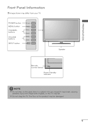
PREPARATION Front Panel Information r Image shown may differ from fragments of glass, or the TV may fall. The floor or the product may break, causing possible injury from your TV. a Do not drag the TV. POWER button MENU button CHANNEL buttons VOLUME buttons INPUT button Speaker Remote Control Sensor Power/Standby Indicator NOTE a Do not step on the glass stand or subject it to any impact.It may be damaged. 9
PREPARATION Front Panel Information r Image shown may differ from fragments of glass, or the TV may fall. The floor or the product may break, causing possible injury from your TV. a Do not drag the TV. POWER button MENU button CHANNEL buttons VOLUME buttons INPUT button Speaker Remote Control Sensor Power/Standby Indicator NOTE a Do not step on the glass stand or subject it to any impact.It may be damaged. 9

Owner's Manual
Page 10
...-air or cable signals to DVI cable (not included). 3 AV (Audio/Video) IN Analog composite connection. Back Panel Information r Image shown may differ from your TV. 32LD400, 42LD400 47LD500 PREPARATION 10 AC IN 9 9 11 2 3 4 / DVI IN RGB IN AV IN ANTENNA/ CABLE IN RGB (PC) AUDIO VIDEO AUDIO 5 1 OPTICAL DIGITAL 1 AUDIO OUT...
...-air or cable signals to DVI cable (not included). 3 AV (Audio/Video) IN Analog composite connection. Back Panel Information r Image shown may differ from your TV. 32LD400, 42LD400 47LD500 PREPARATION 10 AC IN 9 9 11 2 3 4 / DVI IN RGB IN AV IN ANTENNA/ CABLE IN RGB (PC) AUDIO VIDEO AUDIO 5 1 OPTICAL DIGITAL 1 AUDIO OUT...

Owner's Manual
Page 11
... capacity is 1 TB or less for a USB external hard disk and 32 GB or less for USB memory. *A is smaller or equals to operate the TV on DC power. 6 AUDIO OUT For use with AC power. Doesn't support 480i. * HDMI 3: For 47LD500 CAUTION For HDMI IN 3 and USB INPUT a For an...
... capacity is 1 TB or less for a USB external hard disk and 32 GB or less for USB memory. *A is smaller or equals to operate the TV on DC power. 6 AUDIO OUT For use with AC power. Doesn't support 480i. * HDMI 3: For 47LD500 CAUTION For HDMI IN 3 and USB INPUT a For an...
Owner's Manual
Page 12
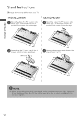
... side down on a cushioned surface to protect the screen from damage. 2 Assemble the TV and install the 6 screws into the holes as shown. (M4 x 6) 2 Remove the screws and detach the stand from damage. NOTE a When assembling the desk type ...stand, make sure the screws are fully tightened (If not tightened fully, the TV can tilt forward after the product installation). DETACHMENT 1 Carefully place the TV screen side down on a cushioned surface to protect the screen from the TV. Do not over tighten. 12 PREPARATION Stand Instructions r Image shown may differ from...
... side down on a cushioned surface to protect the screen from damage. 2 Assemble the TV and install the 6 screws into the holes as shown. (M4 x 6) 2 Remove the screws and detach the stand from damage. NOTE a When assembling the desk type ...stand, make sure the screws are fully tightened (If not tightened fully, the TV can tilt forward after the product installation). DETACHMENT 1 Carefully place the TV screen side down on a cushioned surface to protect the screen from the TV. Do not over tighten. 12 PREPARATION Stand Instructions r Image shown may differ from...

Owner's Manual
Page 13
...and all parts necessary for these kinds of the the wall mount used or the consumer fails to the floor. LG is sold separatedly. When attaching to other building materials, please contact your wall mount on a solid wall perpendicular to follow the... TV a For wall mounts that do not comply installation instructions. specifications. Model VESA (A*B) A B Standard Screw Quantity 32LD400, 42LD400 200 * 200 M6 4 47LD500 400 * 200 M6 4 NOTE a Screw length needed depends ...
...and all parts necessary for these kinds of the the wall mount used or the consumer fails to the floor. LG is sold separatedly. When attaching to other building materials, please contact your wall mount on a solid wall perpendicular to follow the... TV a For wall mounts that do not comply installation instructions. specifications. Model VESA (A*B) A B Standard Screw Quantity 32LD400, 42LD400 200 * 200 M6 4 47LD500 400 * 200 M6 4 NOTE a Screw length needed depends ...

Owner's Manual
Page 14
PREPARATION Desktop Pedestal Installation r Image shown may differ from the wall. 10.1 cm (4 inches) 10.1 cm (4 inches) 10.1 cm (4 inches) 10.1 cm (4 inches) CAUTION a Ensure adequate ventilation by 30º to the left or right direction by following the clearance recommendations. Swivel Stand After installing the TV, you can adjust the TV set manually to suit your TV. For proper ventilation, allow a clearance of heat source. a Do not mount near or above any type of 10.1 cm (4 inches) on all four sides from your viewing position. 14
PREPARATION Desktop Pedestal Installation r Image shown may differ from the wall. 10.1 cm (4 inches) 10.1 cm (4 inches) 10.1 cm (4 inches) 10.1 cm (4 inches) CAUTION a Ensure adequate ventilation by 30º to the left or right direction by following the clearance recommendations. Swivel Stand After installing the TV, you can adjust the TV set manually to suit your TV. For proper ventilation, allow a clearance of heat source. a Do not mount near or above any type of 10.1 cm (4 inches) on all four sides from your viewing position. 14
Owner's Manual
Page 15
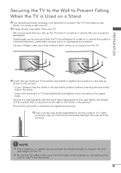
...). Secure the wall brackets with the bolts (sold separately) to support the size and weight of the bracket that children don't climb on the TV are tightened securely. It is safer to a wall so it becomes horizontal between the wall and the product. Ensure the eye-bolts or brackets ... from your product has the bolts in the eye-bolts position before inserting the eye-bolts, loosen the bolts. * Insert the eye-bolts or TV brackets/bolts and tighten them securely in a forward direction, potentially causing injury or damaging the product. We recommend that the height of the bracket ...
...). Secure the wall brackets with the bolts (sold separately) to support the size and weight of the bracket that children don't climb on the TV are tightened securely. It is safer to a wall so it becomes horizontal between the wall and the product. Ensure the eye-bolts or brackets ... from your product has the bolts in the eye-bolts position before inserting the eye-bolts, loosen the bolts. * Insert the eye-bolts or TV brackets/bolts and tighten them securely in a forward direction, potentially causing injury or damaging the product. We recommend that the height of the bracket ...

Owner's Manual
Page 16
... socket) ANTENNA/ CABLE IN Outdoor Antenna (VHF, UHF) RF Coaxial Wire (75 Ω) Single-family Dwellings /Houses (Connect to be split for two TV's, install a 2-Way Signal Splitter. Cable Cable TV Wall Jack RF Coaxial Wire (75 Ω) ANTENNA/ CABLE IN NOTE a If the antenna needs to wall jack for antenna. 16
... socket) ANTENNA/ CABLE IN Outdoor Antenna (VHF, UHF) RF Coaxial Wire (75 Ω) Single-family Dwellings /Houses (Connect to be split for two TV's, install a 2-Way Signal Splitter. Cable Cable TV Wall Jack RF Coaxial Wire (75 Ω) ANTENNA/ CABLE IN NOTE a If the antenna needs to wall jack for antenna. 16

Owner's Manual
Page 17
... use DVI AUDIO Y PB PR VIDEO AUDIO AUDIO OUT r Turn on the digital set-top box. (Refer to the COMPONENT IN AUDIO jack on the TV. / DVI IN RGB IN RGB (PC) AUDIO 1 AV IN VIDEO AUDIO ANTENNA/ CABLE IN OPTICAL DIGITAL AUDIO OUT COMPONENT IN 2 2. Y PB PR L R 1 2 2 Connect the audio... output of the digital set-top box to the COMPONENT IN VIDEO jack on the remote control. EXTERNAL EQUIPMENT SETUP HD Receiver Setup This TV can receive digital over-the-air/digital cable signals without an external digital set-top box. r The pictures in any power cords until you do...
... use DVI AUDIO Y PB PR VIDEO AUDIO AUDIO OUT r Turn on the digital set-top box. (Refer to the COMPONENT IN AUDIO jack on the TV. / DVI IN RGB IN RGB (PC) AUDIO 1 AV IN VIDEO AUDIO ANTENNA/ CABLE IN OPTICAL DIGITAL AUDIO OUT COMPONENT IN 2 2. Y PB PR L R 1 2 2 Connect the audio... output of the digital set-top box to the COMPONENT IN VIDEO jack on the remote control. EXTERNAL EQUIPMENT SETUP HD Receiver Setup This TV can receive digital over-the-air/digital cable signals without an external digital set-top box. r The pictures in any power cords until you do...

Owner's Manual
Page 18
... SETUP HDMI Connection 1. In this case use r Turn on the digital set -top box operation.) r Select the HDMI 1, HDMI 2, or HDMI 3* input source on the TV using the INPUT button on the TV. 2 No separate audio connection is necessary. How to use the latest cables that support High Speed HDMI.
... SETUP HDMI Connection 1. In this case use r Turn on the digital set -top box operation.) r Select the HDMI 1, HDMI 2, or HDMI 3* input source on the TV using the INPUT button on the TV. 2 No separate audio connection is necessary. How to use the latest cables that support High Speed HDMI.

Owner's Manual
Page 19
... 1 Connect the digital set-top box to HDMI/DVI IN 1 or 2 jack on the TV. 2 Connect the digital set -top box to use r Turn on the remote control. r Select the Component input source... on the TV using the INPUT button on the remote control. / DVI IN RGB IN RGB (PC) AUDIO 1..., PB = blue, and PR = red). How to use DVI AUDIO Y PB PR VIDEO AUDIO AUDIO OUT r Turn on the TV. / DVI IN RGB IN RGB (PC) AUDIO 1 AV IN VIDEO AUDIO ANTENNA/ CABLE IN OPTICAL DIGITAL AUDIO OUT COMPONENT IN 2...
... 1 Connect the digital set-top box to HDMI/DVI IN 1 or 2 jack on the TV. 2 Connect the digital set -top box to use r Turn on the remote control. r Select the Component input source... on the TV using the INPUT button on the remote control. / DVI IN RGB IN RGB (PC) AUDIO 1..., PB = blue, and PR = red). How to use DVI AUDIO Y PB PR VIDEO AUDIO AUDIO OUT r Turn on the TV. / DVI IN RGB IN RGB (PC) AUDIO 1 AV IN VIDEO AUDIO ANTENNA/ CABLE IN OPTICAL DIGITAL AUDIO OUT COMPONENT IN 2...
Owner's Manual
Page 20
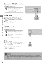
...and Audio Right = red) 2. How to connect 1 Connect the AUDIO/VIDEO jacks between TV and DVD. How to use r Select the HDMI 1, HDMI 2, or HDMI 3* input source on the TV using the INPUT button on the TV. 2 No separate audio connection is necessary. r Refer to the DVD player's manual for ... OUT COMPONENT IN 2 DVI AUDIO Y PB PR VIDEO AUDIO AUDIO OUT 1 VIDEO L R AUDIO HDMI Connection 1. r Select the AV input source on the TV using the INPUT button on the DVD player, insert a DVD. a HDMI Audio Supported Format: Dolby Digital (32 kHz, 44.1 kHz, 48 kHz), Linear PCM...
...and Audio Right = red) 2. How to connect 1 Connect the AUDIO/VIDEO jacks between TV and DVD. How to use r Select the HDMI 1, HDMI 2, or HDMI 3* input source on the TV using the INPUT button on the TV. 2 No separate audio connection is necessary. r Refer to the DVD player's manual for ... OUT COMPONENT IN 2 DVI AUDIO Y PB PR VIDEO AUDIO AUDIO OUT 1 VIDEO L R AUDIO HDMI Connection 1. r Select the AV input source on the TV using the INPUT button on the DVD player, insert a DVD. a HDMI Audio Supported Format: Dolby Digital (32 kHz, 44.1 kHz, 48 kHz), Linear PCM...

Owner's Manual
Page 21
How to use r Insert a video tape into the VCR and press PLAY on the TV. 2 Connect the antenna cable to the AUDIO L(MONO) jack of the VCR. 2. Match the jack colors (Video = yellow,... the VCR and press PLAY on the VCR. (Refer to the VCR owner's manual.) r Select the AV input source on the TV using the INPUT button on the remote control. / DVI IN RGB IN RGB (PC) AUDIO 1 AV IN VIDEO AUDIO ANTENNA/ ...VCR, connect the audio cable from the VCR to the RF antenna in socket of the TV. 21 How to the same channel number. How to use r Set VCR output switch to 3 or 4 and then tune...
How to use r Insert a video tape into the VCR and press PLAY on the TV. 2 Connect the antenna cable to the AUDIO L(MONO) jack of the VCR. 2. Match the jack colors (Video = yellow,... the VCR and press PLAY on the VCR. (Refer to the VCR owner's manual.) r Select the AV input source on the TV using the INPUT button on the remote control. / DVI IN RGB IN RGB (PC) AUDIO 1 AV IN VIDEO AUDIO ANTENNA/ ...VCR, connect the audio cable from the VCR to the RF antenna in socket of the TV. 21 How to the same channel number. How to use r Set VCR output switch to 3 or 4 and then tune...


