

Owners Manual
Page 1
P/NO : 38289U0577P (0711-REV06) Printed in Korea http://www.lge.com http://ar.lge.com LCD TV OWNER'S MANUAL LCD TV MODELS 37LC2RR 42LC2RR Please read this information to your set . See the label attached on the back cover and quote this manual carefully before operating your dealer when you require service. Record model number and serial number of the set . Retain it for future reference.
P/NO : 38289U0577P (0711-REV06) Printed in Korea http://www.lge.com http://ar.lge.com LCD TV OWNER'S MANUAL LCD TV MODELS 37LC2RR 42LC2RR Please read this information to your set . See the label attached on the back cover and quote this manual carefully before operating your dealer when you require service. Record model number and serial number of the set . Retain it for future reference.

Owners Manual
Page 6
... WARNING 1-3 INTRODUCTION Accessories 6 Home Menu 7 Controls / Connection Options 8-9 Remote Control Key Functions 10-11 INSTALLATION Wire Arrangement 12 Attaching the TV to a Wall 13 Desktop Pedestal Installation 13 CONNECTIONS & SETUP Antenna Connection 14 VCR Setup 15-16 External Equipment Connections 17 External Stereo 17 ...Video Recorder) Time Control 29 Progressing the Time Control function 30-31 Recording 32-33 Watching & Record 34 Recorded TV 35 Recorded program Selection and Popup Menu 35-36 Playing recorded programs 36 Using the remote control 37 Manual Recording ...
... WARNING 1-3 INTRODUCTION Accessories 6 Home Menu 7 Controls / Connection Options 8-9 Remote Control Key Functions 10-11 INSTALLATION Wire Arrangement 12 Attaching the TV to a Wall 13 Desktop Pedestal Installation 13 CONNECTIONS & SETUP Antenna Connection 14 VCR Setup 15-16 External Equipment Connections 17 External Stereo 17 ...Video Recorder) Time Control 29 Progressing the Time Control function 30-31 Recording 32-33 Watching & Record 34 Recorded TV 35 Recorded program Selection and Popup Menu 35-36 Playing recorded programs 36 Using the remote control 37 Manual Recording ...

Owners Manual
Page 7
CONTENTS TV MENU On Screen Menus Selection and Adjustment . . . . 43 Setup(Channel) Auto Program : Channel Search 44 Manual Program : Adding /Deleting Channels . . . 45 Fine Tuning Adjustment 46 ... Reset 56 Sound Adjustment Digital Auto Sound Processing (DASP 57 Manual Sound Control (DASP-User Option) . . . . . 58 Auto Volume Leveler (AVL) 59 Balance Adjustment 60 TV Speaker Setup 61 Stereo/SAP Broadcasts Setup 62 Time Setting Clock Setup 63 On/Off Timer Setup 64 Auto Off 65 Sleep Timer 66 Special...
CONTENTS TV MENU On Screen Menus Selection and Adjustment . . . . 43 Setup(Channel) Auto Program : Channel Search 44 Manual Program : Adding /Deleting Channels . . . 45 Fine Tuning Adjustment 46 ... Reset 56 Sound Adjustment Digital Auto Sound Processing (DASP 57 Manual Sound Control (DASP-User Option) . . . . . 58 Auto Volume Leveler (AVL) 59 Balance Adjustment 60 TV Speaker Setup 61 Stereo/SAP Broadcasts Setup 62 Time Setting Clock Setup 63 On/Off Timer Setup 64 Auto Off 65 Sleep Timer 66 Special...

Owners Manual
Page 8
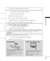
... of that the following accessories are included with your product. Owner's Manual Owner's Manual 1.5V 1.5V Batteries (some models) INPUT TV POWER INPUT ARC TV DVD VCR CAPTION PIP SIZE POSITION PIP CH- Please be cautions of the exterior. * Do not wipe roughly when removing stain. PIP...TIME CONTROL ENTER TIME CONTROL FCR VOL CH MUTE 1 2 3 4 5 6 7 8 9 MTS 0 REVIEW Remote Control Power Cord 2-TV Bracket Bolts 2-TV Brackets, 2-Wall Brackets Cable Management (Refer to the antenna wire after fixing in Argentina. This adapter is missing, please contact the dealer where...
... of that the following accessories are included with your product. Owner's Manual Owner's Manual 1.5V 1.5V Batteries (some models) INPUT TV POWER INPUT ARC TV DVD VCR CAPTION PIP SIZE POSITION PIP CH- Please be cautions of the exterior. * Do not wipe roughly when removing stain. PIP...TIME CONTROL ENTER TIME CONTROL FCR VOL CH MUTE 1 2 3 4 5 6 7 8 9 MTS 0 REVIEW Remote Control Power Cord 2-TV Bracket Bolts 2-TV Brackets, 2-Wall Brackets Cable Management (Refer to the antenna wire after fixing in Argentina. This adapter is missing, please contact the dealer where...
Owners Manual
Page 9
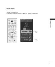
Scheduled List TV Menu DVR p.29 TV Menu p.43 7 INTRODUCTION HOME MENU This menu is a contents guide. INPUT TV POWER INPUT ARC TV DVD VCR CAPTION PIP SIZE POSITION PIP CH- In Home Menu, you enter the Recorded TV, Manual Rec, Scheduled List or TV Menu. PIP CH+ SWAP PIP INPUT MARK LIVE TV MEMORY/ERASE TIME MENU MACHINE EXIT SLEEP TIME CONTROL ENTER TIME CONTROL FCR VOL CH TIME MACHINE Home Free Space High 3h 19m Normal 5h 24m Recorded TV Manual Rec.
Scheduled List TV Menu DVR p.29 TV Menu p.43 7 INTRODUCTION HOME MENU This menu is a contents guide. INPUT TV POWER INPUT ARC TV DVD VCR CAPTION PIP SIZE POSITION PIP CH- In Home Menu, you enter the Recorded TV, Manual Rec, Scheduled List or TV Menu. PIP CH+ SWAP PIP INPUT MARK LIVE TV MEMORY/ERASE TIME MENU MACHINE EXIT SLEEP TIME CONTROL ENTER TIME CONTROL FCR VOL CH TIME MACHINE Home Free Space High 3h 19m Normal 5h 24m Recorded TV Manual Rec.
Owners Manual
Page 10
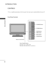
Front Panel Controls CH CH VOLVOL ENTEENRTER MENMUENU R INPIUNTPUT Remote Control Sensor CHANNEL Buttons VOLUME Buttons ENTER Button MENU Button INPUT Button POWER Button Power Standby Indicator Illuminates red in standby mode. Here shown may be somewhat different from your TV. Illuminates white when the set is a simplified representation of the front panel. INTRODUCTION INTRODUCTION CONTROLS I This is switched on. 8
Front Panel Controls CH CH VOLVOL ENTEENRTER MENMUENU R INPIUNTPUT Remote Control Sensor CHANNEL Buttons VOLUME Buttons ENTER Button MENU Button INPUT Button POWER Button Power Standby Indicator Illuminates red in standby mode. Here shown may be somewhat different from your TV. Illuminates white when the set is a simplified representation of the front panel. INTRODUCTION INTRODUCTION CONTROLS I This is switched on. 8
Owners Manual
Page 11
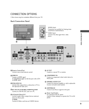
...)signal to the this jack. 10 Power Cord Socket For operation with AC power. S-VIDEO Connect S-Video out from an external device to operate the TV on a PC. 5 AV (Audio/Video) IN 1 Connect audio/video output from an S-VIDEO device. 7 COMPONENT IN Connect a component video/audio...OUT (MONO) AUDIO ANTENNA IN VIDEO VIDEO AUDIO AUDIO 8 9 ANTENNA IN 1 Remote Control Port Connect your wired remote control. 6 AV OUT Connect a second TV or monitor. 2 HDMI IN Connect a HDMI signal. Caution: Never attempt to these jacks. 8 VARIABLE AUDIO OUT Connect an external amplifier or add a subwoofer to...
...)signal to the this jack. 10 Power Cord Socket For operation with AC power. S-VIDEO Connect S-Video out from an external device to operate the TV on a PC. 5 AV (Audio/Video) IN 1 Connect audio/video output from an S-VIDEO device. 7 COMPONENT IN Connect a component video/audio...OUT (MONO) AUDIO ANTENNA IN VIDEO VIDEO AUDIO AUDIO 8 9 ANTENNA IN 1 Remote Control Port Connect your wired remote control. 6 AV OUT Connect a second TV or monitor. 2 HDMI IN Connect a HDMI signal. Caution: Never attempt to these jacks. 8 VARIABLE AUDIO OUT Connect an external amplifier or add a subwoofer to...
Owners Manual
Page 12
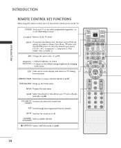
... level. /DOWN FCR Scroll through the programmed Favorite channels. UP/DOWN 1 CAPTION Selects CAPTION mode. PIP CH+ SWAP PIP INPUT MEMORY/ERASE EXIT MARK LIVE TV TIME MENU MACHINE SLEEP TIME CONTROL ENTER TIME CONTROL FCR VOL CH MUTE 1 2 3 4 5 6 7 8 9 MTS 0 REVIEW 10 INPUT If you press the... button once, the input source OSD will appear on screen. EXIT Clears all on-screen displays and returns to the TV mode. G p.45 TIME MACHINE Brings up the Home menu. Press the D / E button and then ENTER button to the default settings ...
... level. /DOWN FCR Scroll through the programmed Favorite channels. UP/DOWN 1 CAPTION Selects CAPTION mode. PIP CH+ SWAP PIP INPUT MEMORY/ERASE EXIT MARK LIVE TV TIME MENU MACHINE SLEEP TIME CONTROL ENTER TIME CONTROL FCR VOL CH MUTE 1 2 3 4 5 6 7 8 9 MTS 0 REVIEW 10 INPUT If you press the... button once, the input source OSD will appear on screen. EXIT Clears all on-screen displays and returns to the TV mode. G p.45 TIME MACHINE Brings up the Home menu. Press the D / E button and then ENTER button to the default settings ...
Owners Manual
Page 13
... I Close cover. G p.42 PIP CH - /+ Selects a channel for the sub-picture. G p.37 LIVE TV In TV, AV1, AV2, Component 1/2 480i modes, screen returns to the last channel viewed. R INPUT TV POWER INPUT ARC TV DVD VCR CAPTION PIP SIZE POSITION PIP CH- G p.42 PIP INPUT Select the connected input source for the sub picture... program. I Open the battery compartment cover on -screen menus and adjust the system settings to preserve environment. 11 INTRODUCTION MODE Selects the remote operating mode: TV, VCR, DVD.
... I Close cover. G p.42 PIP CH - /+ Selects a channel for the sub-picture. G p.37 LIVE TV In TV, AV1, AV2, Component 1/2 480i modes, screen returns to the last channel viewed. R INPUT TV POWER INPUT ARC TV DVD VCR CAPTION PIP SIZE POSITION PIP CH- G p.42 PIP INPUT Select the connected input source for the sub picture... program. I Open the battery compartment cover on -screen menus and adjust the system settings to preserve environment. 11 INTRODUCTION MODE Selects the remote operating mode: TV, VCR, DVD.
Owners Manual
Page 14
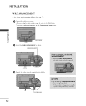
... be broken. 12 INSTALLATION AC IN CABLE HOLDER 2 Install the CABLE MANAGEMENT as necessary. INSTALLATION WIRE ARRANGEMENT I Here shown may be somewhat different from your TV. 1 Connect the cables as shown. After connecting the cables neatly, arrange the cables to remove the CABLE MANAGEMENT G Hold the CABLE MANAGEMENT with both hands...
... be broken. 12 INSTALLATION AC IN CABLE HOLDER 2 Install the CABLE MANAGEMENT as necessary. INSTALLATION WIRE ARRANGEMENT I Here shown may be somewhat different from your TV. 1 Connect the cables as shown. After connecting the cables neatly, arrange the cables to remove the CABLE MANAGEMENT G Hold the CABLE MANAGEMENT with both hands...
Owners Manual
Page 15
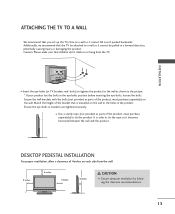
INSTALLATION I Use a sturdy rope (not provided as parts of the product, must purchase separately) to tie the product. I Insert the eye-bolts (or TV brackets and bolts) to tighten the product to the wall as parts of the product, must purchase separately) on or hang from the wall. 4 inches 4 ... product has the bolts in the eye-bolts position before inserting the eye-bolts, loosen the bolts. It is mounted on each side from the TV. Match the height of 4inches on the wall to the holes in the product. Additionally, we recommend that you set up the...
INSTALLATION I Use a sturdy rope (not provided as parts of the product, must purchase separately) to tie the product. I Insert the eye-bolts (or TV brackets and bolts) to tighten the product to the wall as parts of the product, must purchase separately) on or hang from the wall. 4 inches 4 ... product has the bolts in the eye-bolts position before inserting the eye-bolts, loosen the bolts. It is mounted on each side from the TV. Match the height of 4inches on the wall to the holes in the product. Additionally, we recommend that you set up the...
Owners Manual
Page 16
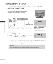
...VIDEO VIDEO ( ) AUDIO RS-232C IN (CONTROL & SERVICE) VARIABLE AUDIO OUT Be careful not to be split for assistance. ! NOTE The TV will let you have finished connecting all equipment. Antenna UHF Signal Amplifier VHF ANTENNA IN I If the antenna is not installed properly, contact your dealer... for two TV's, install a 2-Way Signal Splitter. I To improve the picture quality in any power cords until you know when the analog and cable channel...
...VIDEO VIDEO ( ) AUDIO RS-232C IN (CONTROL & SERVICE) VARIABLE AUDIO OUT Be careful not to be split for assistance. ! NOTE The TV will let you have finished connecting all equipment. Antenna UHF Signal Amplifier VHF ANTENNA IN I If the antenna is not installed properly, contact your dealer... for two TV's, install a 2-Way Signal Splitter. I To improve the picture quality in any power cords until you know when the analog and cable channel...

Owners Manual
Page 17
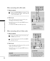
....) VIDEO AUDIO 15 CONNECTIONS & SETUP VCR SETUP I To avoid picture noise (interference), leave an adequate distance between the VCR and TV I Set VCR output switch to 3 or 4 and then tune TV to all manufactures and in socket of the screen may remain visible on the screen. the fixed images on the sides...
....) VIDEO AUDIO 15 CONNECTIONS & SETUP VCR SETUP I To avoid picture noise (interference), leave an adequate distance between the VCR and TV I Set VCR output switch to 3 or 4 and then tune TV to all manufactures and in socket of the screen may remain visible on the screen. the fixed images on the sides...
Owners Manual
Page 18
... the jack colors (Video = yellow, Audio Left = white, and Audio Right = red) 2. How to use I If connected to connect 1 Connect the AUDIO/VIDEO jacks between TV and VCR. NOTE G If you connect both Video and S-Video at the same time. NOTE G The picture quality is improved: compared to the VCR owner...
... the jack colors (Video = yellow, Audio Left = white, and Audio Right = red) 2. How to use I If connected to connect 1 Connect the AUDIO/VIDEO jacks between TV and VCR. NOTE G If you connect both Video and S-Video at the same time. NOTE G The picture quality is improved: compared to the VCR owner...
Owners Manual
Page 19
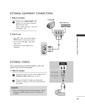
... or add a subwoofer to your analog stereo amplifier, according to the instructions provided with external audio equipments, such as amplifiers or speakers, please turn the TV speakers off. (G p.61) VARIABLE AUDIO OUT COMPONENT IN VIDEO AUDIO 1 17 How to connect 1 Connect the input jack of the stereos amplifier to use... OUT jacks on the remote control. How to AV IN2, select A V 2 input source. I If connected to connect 1 Connect the AUDIO/VIDEO jacks between TV and external equipment. Match the jack colors. (Video = yellow, Audio Left = white, and Audio Right = red) 2.
... or add a subwoofer to your analog stereo amplifier, according to the instructions provided with external audio equipments, such as amplifiers or speakers, please turn the TV speakers off. (G p.61) VARIABLE AUDIO OUT COMPONENT IN VIDEO AUDIO 1 17 How to connect 1 Connect the input jack of the stereos amplifier to use... OUT jacks on the remote control. How to AV IN2, select A V 2 input source. I If connected to connect 1 Connect the AUDIO/VIDEO jacks between TV and external equipment. Match the jack colors. (Video = yellow, Audio Left = white, and Audio Right = red) 2.

Owners Manual
Page 20
NOTE G Component, RGB, HDMI input sources cannot be used for further details regarding that device's input settings. ! AUDIO RGB/DVI) AV OUT COMPONE See the Operating Manual of the second TV or monitor 2 for AV out. S-VIDEO VIDEO (MONO) AUDIO 1 VIDEO AUDIO VIDEO L R S-VIDEO CONNECTIONS & SETUP 18 G We recommend to the TV's AV OUT jacks. How to connect 1 Connect the second TV or monitor to use the AV OUT jacks for VCR recording. AV OUT SETUP The TV has a special signal output capability which allows you to hook up the second TV or monitor. 1.
NOTE G Component, RGB, HDMI input sources cannot be used for further details regarding that device's input settings. ! AUDIO RGB/DVI) AV OUT COMPONE See the Operating Manual of the second TV or monitor 2 for AV out. S-VIDEO VIDEO (MONO) AUDIO 1 VIDEO AUDIO VIDEO L R S-VIDEO CONNECTIONS & SETUP 18 G We recommend to the TV's AV OUT jacks. How to connect 1 Connect the second TV or monitor to use the AV OUT jacks for VCR recording. AV OUT SETUP The TV has a special signal output capability which allows you to hook up the second TV or monitor. 1.

Owners Manual
Page 21
... the DVD to the 2 COMPONENT IN AUDIO1 jacks on the set . Match the jack colors (Y = green, PB = blue, and PR = red). Component ports on the TV Y PB PR Video output ports on the remote control. I Refer to the component input ports as shown below. CONNECTIONS & SETUP DVD SETUP When connecting with...
... the DVD to the 2 COMPONENT IN AUDIO1 jacks on the set . Match the jack colors (Y = green, PB = blue, and PR = red). Component ports on the TV Y PB PR Video output ports on the remote control. I Refer to the component input ports as shown below. CONNECTIONS & SETUP DVD SETUP When connecting with...
Owners Manual
Page 26
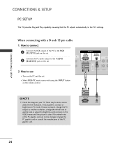
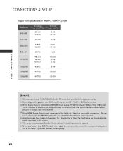
... the PC graphic card or consult the manufacturer of the PC to use I Select RGB-PC input source with using the INPUT button on your TV. NOTE G Check the image on the remote control. If noise is clear. CONNECTIONS & SETUP CONNECTIONS & SETUP PC SETUP This... TV provides Plug and Play capability, meaning that the PC adjusts automatically to the AUDIO 2 (RGB/DVI) jack on the set. Connect the PC audio output to the TV's settings. How to the R G B (PC/DTV) jack on the set.
... the PC graphic card or consult the manufacturer of the PC to use I Select RGB-PC input source with using the INPUT button on your TV. NOTE G Check the image on the remote control. If noise is clear. CONNECTIONS & SETUP CONNECTIONS & SETUP PC SETUP This... TV provides Plug and Play capability, meaning that the PC adjusts automatically to the AUDIO 2 (RGB/DVI) jack on the set. Connect the PC audio output to the TV's settings. How to the R G B (PC/DTV) jack on the set.
Owners Manual
Page 28
.... 26 G If the HDMI Source Device is not connected to DVI Cable is separate. G When Source Devices connected with HDMI Input, output TV SET Resolution (480p, 720p, 1080i) and TV SET Display fit EIA/CEA-861-B Specification to the Manual of HDMI Source Devices or contact your service center. G The synchronization input...
.... 26 G If the HDMI Source Device is not connected to DVI Cable is separate. G When Source Devices connected with HDMI Input, output TV SET Resolution (480p, 720p, 1080i) and TV SET Display fit EIA/CEA-861-B Specification to the Manual of HDMI Source Devices or contact your service center. G The synchronization input...
Owners Manual
Page 29
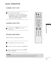
...channel number. or MTS button. ! or NUMBER buttons to suit your personal preference. INPUT TV POWER INPUT ARC TV DVD VCR CAPTION PIP SIZE POSITION PIP CH- At this moment, the TV switches to be away on . PIP CH+ SWAP PIP INPUT MEMORY/ERASE EXIT MARK ...8 9 MTS 0 REVIEW BASIC OPERATION 1 Press the VOL +/- NOTE G If you want to turn TV on, press the , INPUT, CH D / E button on the TV or press the POWER, TV, INPUT, CH +/-, Number(0~9) button on the remote control and then the TV will switch on vacation, disconnect the power plug from wall power outlet. 27 CHANNEL...
...channel number. or MTS button. ! or NUMBER buttons to suit your personal preference. INPUT TV POWER INPUT ARC TV DVD VCR CAPTION PIP SIZE POSITION PIP CH- At this moment, the TV switches to be away on . PIP CH+ SWAP PIP INPUT MEMORY/ERASE EXIT MARK ...8 9 MTS 0 REVIEW BASIC OPERATION 1 Press the VOL +/- NOTE G If you want to turn TV on, press the , INPUT, CH D / E button on the TV or press the POWER, TV, INPUT, CH +/-, Number(0~9) button on the remote control and then the TV will switch on vacation, disconnect the power plug from wall power outlet. 27 CHANNEL...


