Owner's Manual (English)
Page 2
... connected to the HDMI (high-definition multimedia interface), LG TV with one remote control. TruSurround XT technology is a trademark of a full digital image processor, six different main picture quality factors. With HDMI CEC support of digital television, HDTV formats include 1080i and 720p resolutions. It has three HDMI ports that connect audio and video devices with this logo displays Full HD(high-definition) 1080p native resolution by receiving and processing a Full HD 1080p signal...
... connected to the HDMI (high-definition multimedia interface), LG TV with one remote control. TruSurround XT technology is a trademark of a full digital image processor, six different main picture quality factors. With HDMI CEC support of digital television, HDTV formats include 1080i and 720p resolutions. It has three HDMI ports that connect audio and video devices with this logo displays Full HD(high-definition) 1080p native resolution by receiving and processing a Full HD 1080p signal...
Owner's Manual (English)
Page 3
... a Class B digital device, pursuant to Part 15 of the cable entry as close to correct the interference by turning the equipment off and on a circuit different from LG Electronics. REFER TO QUALIFIED SERVICE PERSONNEL. Connect the equipment to an outlet on , the user is no guarantee that to which can radiate radio frequency energy and, if not installed and used in...
... a Class B digital device, pursuant to Part 15 of the cable entry as close to correct the interference by turning the equipment off and on a circuit different from LG Electronics. REFER TO QUALIFIED SERVICE PERSONNEL. Connect the equipment to an outlet on , the user is no guarantee that to which can radiate radio frequency energy and, if not installed and used in...
Owner's Manual (English)
Page 6
... Installation 16 Vesa Wall Mounting 16 Antenna or Cable Connection 17 EXTERNAL EQUIPMENT SETUP HD Receiver Setup 18 DVD Setup 21 VCR Setup 23 Other A/V Source Setup 25 PC Setup 26 USB In Setup 32 Audio Out Setup 33 WATCHING TV / CHANNEL CONTROL Remote Control Functions 34 Turning on TV 36 Channel Selection 37 Volume Adjustment 38 On-Screen Menus Selection 39 Channel Setup - Channel Editing 42 Input List 43 SimpLink 44 Input Label 46 4 MEDIAHOST MEDIAHOST Entry Modes 47 Photo List 48 Music List 52 PICTURE CONTROL Picture Size (Aspect Ratio) Control 54 Preset Picture...
... Installation 16 Vesa Wall Mounting 16 Antenna or Cable Connection 17 EXTERNAL EQUIPMENT SETUP HD Receiver Setup 18 DVD Setup 21 VCR Setup 23 Other A/V Source Setup 25 PC Setup 26 USB In Setup 32 Audio Out Setup 33 WATCHING TV / CHANNEL CONTROL Remote Control Functions 34 Turning on TV 36 Channel Selection 37 Volume Adjustment 38 On-Screen Menus Selection 39 Channel Setup - Channel Editing 42 Input List 43 SimpLink 44 Input Label 46 4 MEDIAHOST MEDIAHOST Entry Modes 47 Photo List 48 Music List 52 PICTURE CONTROL Picture Size (Aspect Ratio) Control 54 Preset Picture...
Owner's Manual (English)
Page 13
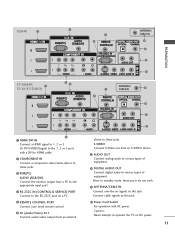
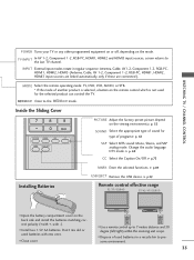
... AUDIO R USB IN S-VIDEO ANTENNA/ CABLE IN AV IN 2 ANTENNA/ CABLE IN HDMI/DVI IN Connect a HDMI signal to these jacks. RS-232C IN (CONTROL & SERVICE) PORT Connect to this jack. S-VIDEO Connect S-Video out from a PC to HDMI cable. Power Cord Socket For operation with a DVI to the appropriate input port. Or DVI (VIDEO)signal to various types of equipment. REMOTE CONTROL PORT Connect your wired remote control. AUDIO OUT Connect analog audio to the 1, 2 or 3 port with AC power. COMPONENT IN Connect a component video/audio device to 1, 2 or 3. DIGITAL AUDIO OUT Connect digital...
... AUDIO R USB IN S-VIDEO ANTENNA/ CABLE IN AV IN 2 ANTENNA/ CABLE IN HDMI/DVI IN Connect a HDMI signal to these jacks. RS-232C IN (CONTROL & SERVICE) PORT Connect to this jack. S-VIDEO Connect S-Video out from a PC to HDMI cable. Power Cord Socket For operation with a DVI to the appropriate input port. Or DVI (VIDEO)signal to various types of equipment. REMOTE CONTROL PORT Connect your wired remote control. AUDIO OUT Connect analog audio to the 1, 2 or 3 port with AC power. COMPONENT IN Connect a component video/audio device to 1, 2 or 3. DIGITAL AUDIO OUT Connect digital...
Owner's Manual (English)
Page 20
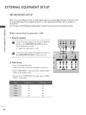
... of the digital set -top box. (Refer to the owner's manual for Digital Contents. How to use I Turn on the set top box to the figure as shown below. When connecting Component cable 1. Y PB PR L R 1 2 2. EXTERNAL EQUIPMENT SETUP EXTERNAL EQUIPMENT SETUP HD RECEIVER SETUP This TV can receive Digital Over-the-air/Cable signals without an external digital set . Match the jack colors (Y = green, PB = blue, and PR = red). 2 Connect the audio output of the digital set . I Select COMPONENT 1 input source with using the INPUT button on the set -top box. This TV supports HDCP...
... of the digital set -top box. (Refer to the owner's manual for Digital Contents. How to use I Turn on the set top box to the figure as shown below. When connecting Component cable 1. Y PB PR L R 1 2 2. EXTERNAL EQUIPMENT SETUP EXTERNAL EQUIPMENT SETUP HD RECEIVER SETUP This TV can receive Digital Over-the-air/Cable signals without an external digital set . Match the jack colors (Y = green, PB = blue, and PR = red). 2 Connect the audio output of the digital set . I Select COMPONENT 1 input source with using the INPUT button on the set -top box. This TV supports HDCP...
Owner's Manual (English)
Page 21
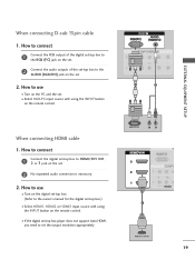
... OUTPUT L R (DVI) 1 HDMI-DTV OUTPUT 19 RGB 1 2 When connecting HDMI cable 1. I Select HDMI1, HDMI2 or HDMI3 input source with using the INPUT button on the set. 2. How to connect 1 Connect the RGB output of the set . I Turn on the remote control. How to use I If the digital set-top box player does not support Auto HDMI, you need to HDMI/DVI IN1, 2 or 3 jack on the set the output resolution appropriately. EXTERNAL EQUIPMENT SETUP When connecting D-sub 15pin cable 1. How to connect 1 Connect the digital set-top box to set . 2 No separated audio connection...
... OUTPUT L R (DVI) 1 HDMI-DTV OUTPUT 19 RGB 1 2 When connecting HDMI cable 1. I Select HDMI1, HDMI2 or HDMI3 input source with using the INPUT button on the set. 2. How to connect 1 Connect the RGB output of the set . I Turn on the remote control. How to use I If the digital set-top box player does not support Auto HDMI, you need to HDMI/DVI IN1, 2 or 3 jack on the set the output resolution appropriately. EXTERNAL EQUIPMENT SETUP When connecting D-sub 15pin cable 1. How to connect 1 Connect the digital set-top box to set . 2 No separated audio connection...
Owner's Manual (English)
Page 22
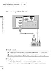
EXTERNAL EQUIPMENT SETUP When connecting HDMI to the owner's manual for the digital set-top box.) I Select HDMI1, HDMI2 or HDMI3 input source with using the INPUT button on the set. 2. How to connect 1 Connect the DVI output of the digital set-top box to the HDMI/DVI IN1, 2 or 3 jack on the set. 2 Connect the audio output of the digital set -top box. (Refer to DVI cable RGB 3 EXTERNAL EQUIPMENT SETUP 2 1 DVI-DTV OUTPUT L R 1. How to use I Turn on the digital set -top box to the AUDIO(RGB/DVI) jack on the remote control. 20
EXTERNAL EQUIPMENT SETUP When connecting HDMI to the owner's manual for the digital set-top box.) I Select HDMI1, HDMI2 or HDMI3 input source with using the INPUT button on the set. 2. How to connect 1 Connect the DVI output of the digital set-top box to the HDMI/DVI IN1, 2 or 3 jack on the set. 2 Connect the audio output of the digital set -top box. (Refer to DVI cable RGB 3 EXTERNAL EQUIPMENT SETUP 2 1 DVI-DTV OUTPUT L R 1. How to use I Turn on the digital set -top box to the AUDIO(RGB/DVI) jack on the remote control. 20
Owner's Manual (English)
Page 23
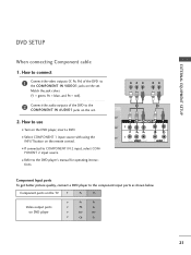
...DVD player's manual for operating instruc- I Refer to the component input ports as shown below. I Select COMPONENT 1 input source with using the INPUT button on the DVD player, insert a DVD. Match the jack colors (Y = green, PB = blue, and PR = red). 2 Connect the audio outputs of the DVD to use I If connected to the COMPONENT IN AUDIO1 jacks on DVD player Y PB PR Y Pb Pr Y B-Y R-Y Y Cb Cr 21 I Turn on the remote control. Component ports on the TV Y PB PR Video output ports on the set . tions. PONENT 2 input source. EXTERNAL EQUIPMENT SETUP DVD SETUP...
...DVD player's manual for operating instruc- I Refer to the component input ports as shown below. I Select COMPONENT 1 input source with using the INPUT button on the DVD player, insert a DVD. Match the jack colors (Y = green, PB = blue, and PR = red). 2 Connect the audio outputs of the DVD to use I If connected to the COMPONENT IN AUDIO1 jacks on DVD player Y PB PR Y Pb Pr Y B-Y R-Y Y Cb Cr 21 I Turn on the remote control. Component ports on the TV Y PB PR Video output ports on the set . tions. PONENT 2 input source. EXTERNAL EQUIPMENT SETUP DVD SETUP...
Owner's Manual (English)
Page 24
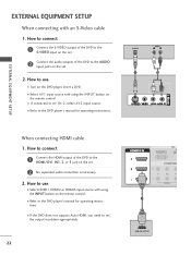
... audio connection is necessary. 2. How to connect 1 Connect the S-VIDEO output of the DVD to the DVD player's manual for operating instructions. I Turn on the DVD player, insert a DVD. How to the DVD player's manual for operating instructions. I Refer to use I Refer to the AUDIO input jacks on the set the output resolution appropriately. 22 1 HDMI-DVD OUTPUT I If the DVD does not support Auto HDMI, you need to AV IN 2, select A V 2 input source. I If connected to set . 2. EXTERNAL EQUIPMENT SETUP When connecting with using the INPUT button on the remote control...
... audio connection is necessary. 2. How to connect 1 Connect the S-VIDEO output of the DVD to the DVD player's manual for operating instructions. I Turn on the DVD player, insert a DVD. How to the DVD player's manual for operating instructions. I Refer to use I Refer to the AUDIO input jacks on the set the output resolution appropriately. 22 1 HDMI-DVD OUTPUT I If the DVD does not support Auto HDMI, you need to AV IN 2, select A V 2 input source. I If connected to set . 2. EXTERNAL EQUIPMENT SETUP When connecting with using the INPUT button on the remote control...

Owner's Manual (English)
Page 26
... VCR owner's manual.) I Select A V 1 input source with using the INPUT button on the set . How to AV IN 2, select A V 2 input source. compared to normal composite (RCA cable) input. 2 Connect the audio outputs of the set . 2. How to use I Insert a video tape into the VCR and press PLAY on the VCR. (Refer to the AUDIO input jacks on the remote control. EXTERNAL EQUIPMENT SETUP EXTERNAL EQUIPMENT SETUP When connecting with an S-Video cable 1. When connecting with a RCA cable 1. VIDEO L R S-VIDEO ANT IN ANTENNA/ OUTPUT ANT OUT SWITCH CABLE IN...
... VCR owner's manual.) I Select A V 1 input source with using the INPUT button on the set . How to AV IN 2, select A V 2 input source. compared to normal composite (RCA cable) input. 2 Connect the audio outputs of the set . 2. How to use I Insert a video tape into the VCR and press PLAY on the VCR. (Refer to the AUDIO input jacks on the remote control. EXTERNAL EQUIPMENT SETUP EXTERNAL EQUIPMENT SETUP When connecting with an S-Video cable 1. When connecting with a RCA cable 1. VIDEO L R S-VIDEO ANT IN ANTENNA/ OUTPUT ANT OUT SWITCH CABLE IN...
Owner's Manual (English)
Page 28
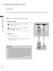
... INPUT button on the PC and the set . 2. There may be changed, change the PC graphic card or consult the manufacturer of the PC to the RGB (PC) jack on the set. 2 Connect the PC audio output to connect 1 Connect the RGB output of the PC graphic card. EXTERNAL EQUIPMENT SETUP EXTERNAL EQUIPMENT SETUP PC SETUP This TV provides Plug and Play capability, meaning that the PC adjusts automatically to another resolution, change...
... INPUT button on the PC and the set . 2. There may be changed, change the PC graphic card or consult the manufacturer of the PC to the RGB (PC) jack on the set. 2 Connect the PC audio output to connect 1 Connect the RGB output of the PC graphic card. EXTERNAL EQUIPMENT SETUP EXTERNAL EQUIPMENT SETUP PC SETUP This TV provides Plug and Play capability, meaning that the PC adjusts automatically to another resolution, change...
Owner's Manual (English)
Page 29
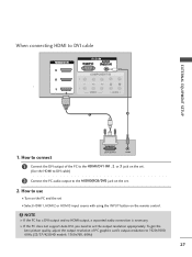
... the set the output resolution appropriately. How to 1920x1080, 60Hz.(32/37/42LB4D models: 1360x768, 60Hz) 27 How to connect DVI-PC OUTPUT AUDIO 1 Connect the DVI output of PC graphics card's output resolution to use I Turn on the PC and the set I Select HDMI1, HDMI2 or HDMI3 input source with using the INPUT button on the set. 2. To get the best picture quality, adjust the output resolution of the PC to DVI cable RGB EXTERNAL EQUIPMENT SETUP...
... the set the output resolution appropriately. How to 1920x1080, 60Hz.(32/37/42LB4D models: 1360x768, 60Hz) 27 How to connect DVI-PC OUTPUT AUDIO 1 Connect the DVI output of PC graphics card's output resolution to use I Turn on the PC and the set I Select HDMI1, HDMI2 or HDMI3 input source with using the INPUT button on the set. 2. To get the best picture quality, adjust the output resolution of the PC to DVI cable RGB EXTERNAL EQUIPMENT SETUP...
Owner's Manual (English)
Page 37
... sequence: Antenna, Cable, AV1-2, Component 1-2, RGB-PC, HDMI1, HDMI2, HDMI3 (Antenna, Cable, AV 1-2, Component 1-2, RGB-PC, HDMI1, HDMI2, HDMI3 input sources are linked automatically, only if these are connected ). G p.49 USB EJECT Remove the USB device. DAY + LIVE TV INPUT MODE DAY - MEDIAHOST MEDIAHOST Enter to the last TV channel. I Install two 1.5V AA batteries. I Use a remote control up to preserve environment. 35 STB MEDIA HOST WATCHING TV / CHANNEL CONTROL POWER Turns your TV or any other programmed equipment...
... sequence: Antenna, Cable, AV1-2, Component 1-2, RGB-PC, HDMI1, HDMI2, HDMI3 (Antenna, Cable, AV 1-2, Component 1-2, RGB-PC, HDMI1, HDMI2, HDMI3 input sources are linked automatically, only if these are connected ). G p.49 USB EJECT Remove the USB device. DAY + LIVE TV INPUT MODE DAY - MEDIAHOST MEDIAHOST Enter to the last TV channel. I Install two 1.5V AA batteries. I Use a remote control up to preserve environment. 35 STB MEDIA HOST WATCHING TV / CHANNEL CONTROL POWER Turns your TV or any other programmed equipment...

Owner's Manual (English)
Page 42
...the SETUP BACK menu. Analog TV antenna Digital DTV antenna Analog CATV cable Digital CADTV cable 40 Auto Tuning Manual Tuning Channel Edit Processing Auto Tuning... WATCHING TV /CHANNEL CONTROL TV INPUT CHANNEL SETUP A HOST STB MEDIA HOST Auto Scan(Auto Tuning) TV INPUT STB MEDIA HOST Automatically finds all channels available through antenna or cable inputs, and stores them in memory on . Manual Tuning BACK Channel Edit BACK C PICTURE SOUND SAP PICTURE SAP CC PICTURE SOUND CC MARK USB EJECT MARK USB EJECT MARK USB EJECT 2 Press the G button and then use...
...the SETUP BACK menu. Analog TV antenna Digital DTV antenna Analog CATV cable Digital CADTV cable 40 Auto Tuning Manual Tuning Channel Edit Processing Auto Tuning... WATCHING TV /CHANNEL CONTROL TV INPUT CHANNEL SETUP A HOST STB MEDIA HOST Auto Scan(Auto Tuning) TV INPUT STB MEDIA HOST Automatically finds all channels available through antenna or cable inputs, and stores them in memory on . Manual Tuning BACK Channel Edit BACK C PICTURE SOUND SAP PICTURE SAP CC PICTURE SOUND CC MARK USB EJECT MARK USB EJECT MARK USB EJECT 2 Press the G button and then use...
Owner's Manual (English)
Page 45
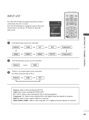
.../CATV. Component 1-2 : Select it when using the DVD or the Digital set -top box depend on connector. Cable: Select it when watching the VCR or external equipment. HDMI, HDMI2, HDMI3 : Select it when using DVD, PC or Digital set -top box depend on connector. 43 Press the ENTER button to change the input to AV 2) Antenna Cable AV2 RGB-PC Component2 PICTURE SOUND SAP CC MARK USB EJECT Antenna : Select it when using PC...
.../CATV. Component 1-2 : Select it when using the DVD or the Digital set -top box depend on connector. Cable: Select it when watching the VCR or external equipment. HDMI, HDMI2, HDMI3 : Select it when using DVD, PC or Digital set -top box depend on connector. 43 Press the ENTER button to change the input to AV 2) Antenna Cable AV2 RGB-PC Component2 PICTURE SOUND SAP CC MARK USB EJECT Antenna : Select it when using PC...
Owner's Manual (English)
Page 46
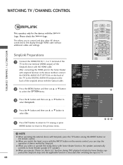
... devices connected to TV. 44 TIMER RATIO SIMPLINK Language Input label SimpLink Key Lock Caption Set ID : English : Off : Off : Off : 1 PICTURE SOUND BACK SAP CC MARK USB EJECT Language Input label SimpLink Key Lock Caption Set ID G Off On 5 Press EXIT button to return to TV viewing or press MENU button to return to the rear terminal (HDMI output) of the SimpLink device with the HDMI cable. MMEENNUU BRIGHT + WATCHING TV / CHANNEL CONTROL SimpLink Preparations 1 Connect the HDMI...
... devices connected to TV. 44 TIMER RATIO SIMPLINK Language Input label SimpLink Key Lock Caption Set ID : English : Off : Off : Off : 1 PICTURE SOUND BACK SAP CC MARK USB EJECT Language Input label SimpLink Key Lock Caption Set ID G Off On 5 Press EXIT button to return to TV viewing or press MENU button to return to the rear terminal (HDMI output) of the SimpLink device with the HDMI cable. MMEENNUU BRIGHT + WATCHING TV / CHANNEL CONTROL SimpLink Preparations 1 Connect the HDMI...
Owner's Manual (English)
Page 84
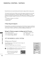
... block specific channels, ratings, and external viewing sources. The default setting is to select the LOCK menu. To use this menu. 1 Press the MENU button and then use the Movie Rating System (MPAA) only. Most television programs and television movies can be blocked. 2. Then, press the G button. It is required to gain access to be blocked by TV Rating and/or Individual Categories. Enter Password 82 BACK PICTURE SOUND SAP CC BACK TV INPUT STB MEDIA...
... block specific channels, ratings, and external viewing sources. The default setting is to select the LOCK menu. To use this menu. 1 Press the MENU button and then use the Movie Rating System (MPAA) only. Most television programs and television movies can be blocked. 2. Then, press the G button. It is required to gain access to be blocked by TV Rating and/or Individual Categories. Enter Password 82 BACK PICTURE SOUND SAP CC BACK TV INPUT STB MEDIA...
Owner's Manual (English)
Page 96
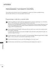
... the POWER button. If the device turned off and it responds properly the remote control need not be programmed to store the code. the currently selected device button is successful. 4 Press the MENU button to operate the device. APPENDIX 94 If not, the remote should be programmed. If the device is turned off , the programming is illuminated. When pressing the button, the light blinks at the same time for 20...
... the POWER button. If the device turned off and it responds properly the remote control need not be programmed to store the code. the currently selected device button is successful. 4 Press the MENU button to operate the device. APPENDIX 94 If not, the remote should be programmed. If the device is turned off , the programming is illuminated. When pressing the button, the light blinks at the same time for 20...
Owner's Manual (English)
Page 105
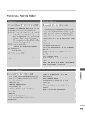
... [Command2][ ][Set ID][ ][OK][Data][x] The TV transmits ACK (acknowledgement) based on ack message, it send the power on this model, TV will not send the status during the standby mode. At this model, TV will be like below . Transmit 'FF' data to choose desired TV ID number in Setup menu. When it send the power on ack message, it will send the 'a', 'b' [NG] : use the...
... [Command2][ ][Set ID][ ][OK][Data][x] The TV transmits ACK (acknowledgement) based on ack message, it send the power on this model, TV will not send the status during the standby mode. At this model, TV will be like below . Transmit 'FF' data to choose desired TV ID number in Setup menu. When it send the power on ack message, it will send the 'a', 'b' [NG] : use the...

Owner's Manual (English)
Page 109
... 0: Channel Delete Data 1: Channel Add Acknowledgement [b][ ][Set ID][ ][OK/NG][Data][x] 24. Transmission [m][c][ ][Set ID][ ][Data][Cr]s Data Key code: Refer to page 99. Analog channel: NTSC cable, channel number(35), main picture Command: ma 00 23 xx xx xx xx 01 attribute(0x01): main picture, two part(it's not mandatory), using physical channel, ATSC air. Key (Command: m c) To send IR remote key code. Digital channel: ATSC air, channel number(physical...
... 0: Channel Delete Data 1: Channel Add Acknowledgement [b][ ][Set ID][ ][OK/NG][Data][x] 24. Transmission [m][c][ ][Set ID][ ][Data][Cr]s Data Key code: Refer to page 99. Analog channel: NTSC cable, channel number(35), main picture Command: ma 00 23 xx xx xx xx 01 attribute(0x01): main picture, two part(it's not mandatory), using physical channel, ATSC air. Key (Command: m c) To send IR remote key code. Digital channel: ATSC air, channel number(physical...


