User Manual
Page 2
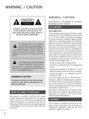
... on , the user is connected. - Operation is no guarantee that may not cause (harmful) interference, and (2) this equipment does cause harmful interference to radio or television reception, which are designed to comply with part 15 of the building, as close to the following measures: - NO USER SERVICEABLE PARTS INSIDE. REFER TO QUALIFIED SERVICE PERSONNEL. The lightning flash with the instructions, may be...
... on , the user is connected. - Operation is no guarantee that may not cause (harmful) interference, and (2) this equipment does cause harmful interference to radio or television reception, which are designed to comply with part 15 of the building, as close to the following measures: - NO USER SERVICEABLE PARTS INSIDE. REFER TO QUALIFIED SERVICE PERSONNEL. The lightning flash with the instructions, may be...
User Manual
Page 4
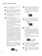
... electrician install a separate circuit breaker. Overloaded wall outlets, loose or damaged wall outlets, extension cords, frayed power cords, or damaged or cracked wire insulation are not possible, have the cord replaced with an exact replacement part by the hanging power and signal cables on shelves above the unit). 17 GROUNDING Ensure that appliances be certain. Do not use of this product to plugs, wall outlets, and...
... electrician install a separate circuit breaker. Overloaded wall outlets, loose or damaged wall outlets, extension cords, frayed power cords, or damaged or cracked wire insulation are not possible, have the cord replaced with an exact replacement part by the hanging power and signal cables on shelves above the unit). 17 GROUNDING Ensure that appliances be certain. Do not use of this product to plugs, wall outlets, and...
User Manual
Page 5
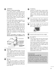
... (Only Hg lamp used LCD TV) The fluorescent lamp used in accordance to the National Electrical Code, ANSI/NFPA 70 Ground Clamp Antenna Lead in excessively dusty places. 24 If you smell smoke or other materials (e.g.) plastic while plugged in a confined space such as tiny red, green, or blue spots. This is normal, there is installed, follow the precautions...
... (Only Hg lamp used LCD TV) The fluorescent lamp used in accordance to the National Electrical Code, ANSI/NFPA 70 Ground Clamp Antenna Lead in excessively dusty places. 24 If you smell smoke or other materials (e.g.) plastic while plugged in a confined space such as tiny red, green, or blue spots. This is normal, there is installed, follow the precautions...
User Manual
Page 6
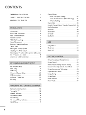
... is used on a stand 18 Antenna or Cable Connection 19 EXTERNAL EQUIPMENT SETUP HD Receiver Setup 20 DVD Setup 23 VCR Setup 25 Other A/V Source Setup 27 USB Connection 28 Audio out Connection 29 PC Setup 30 WATCHING TV / CHANNEL CONTROL Remote Control Functions 36 Turning On TV 38 Channel Selection 38 Volume Adjustment 38 Initial Setting 39 On-Screen Menus Selection 40 Quick Menu 41 6 Channel Setup - Auto Scan (Auto Tuning 42 - User Mode 67 Picture Improvement Technology 68 Expert Picture Control 69 Energy Saving 72 Picture Reset 73 Power Indicator 74 Demo Mode...
... is used on a stand 18 Antenna or Cable Connection 19 EXTERNAL EQUIPMENT SETUP HD Receiver Setup 20 DVD Setup 23 VCR Setup 25 Other A/V Source Setup 27 USB Connection 28 Audio out Connection 29 PC Setup 30 WATCHING TV / CHANNEL CONTROL Remote Control Functions 36 Turning On TV 38 Channel Selection 38 Volume Adjustment 38 Initial Setting 39 On-Screen Menus Selection 40 Quick Menu 41 6 Channel Setup - Auto Scan (Auto Tuning 42 - User Mode 67 Picture Improvement Technology 68 Expert Picture Control 69 Energy Saving 72 Picture Reset 73 Power Indicator 74 Demo Mode...
User Manual
Page 7
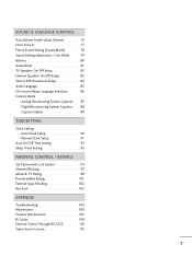
...Caption Option 89 TIME SETTING Clock Setting - Analog Broadcasting System Captions 87 - Digital Broadcasting System Captions 88 - Auto Clock Setup 90 Manual Clock Setup 91 Auto On/Off Time Setting 92 Sleep Timer Setting 93 PARENTAL CONTROL / RATINGS Set Password & Lock System 94 Channel Blocking 97 Movie & TV Rating 98 Downloadable Rating 101 External Input Blocking 102 Key Lock 103 APPENDIX Troubleshooting 104 Maintenance 106 Product Specifications 107 IR Codes 108 External Control Through RS-232C 110 Open Source License 116 7 SOUND & LANGUAGE CONTROL Auto Volume...
...Caption Option 89 TIME SETTING Clock Setting - Analog Broadcasting System Captions 87 - Digital Broadcasting System Captions 88 - Auto Clock Setup 90 Manual Clock Setup 91 Auto On/Off Time Setting 92 Sleep Timer Setting 93 PARENTAL CONTROL / RATINGS Set Password & Lock System 94 Channel Blocking 97 Movie & TV Rating 98 Downloadable Rating 101 External Input Blocking 102 Key Lock 103 APPENDIX Troubleshooting 104 Maintenance 106 Product Specifications 107 IR Codes 108 External Control Through RS-232C 110 Open Source License 116 7 SOUND & LANGUAGE CONTROL Auto Volume...
User Manual
Page 20
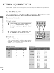
... to use I Turn on the digital set-top box. (Refer to the COMPONENT IN AUDIO jacks on the TV. 2. However, if you have finished connecting all equipment. Match the jack colors (Y = green, PB = blue, and PR = red). Component Connection 1. EXTERNAL EQUIPMENT SETUP I Select the Component input source on the TV using the INPUT button on the remote control. 1 2 RJP AV IN 1 VIDEO AUDIO 2 L(MONO) R 1 VIDEO COMPONENT IN L AUDIO R L R SPEAKER OUT /DVI IN REMO CONTRO Supported Resolutions Signal Component 480i Yes 480p Yes 720p Yes...
... to use I Turn on the digital set-top box. (Refer to the COMPONENT IN AUDIO jacks on the TV. 2. However, if you have finished connecting all equipment. Match the jack colors (Y = green, PB = blue, and PR = red). Component Connection 1. EXTERNAL EQUIPMENT SETUP I Select the Component input source on the TV using the INPUT button on the remote control. 1 2 RJP AV IN 1 VIDEO AUDIO 2 L(MONO) R 1 VIDEO COMPONENT IN L AUDIO R L R SPEAKER OUT /DVI IN REMO CONTRO Supported Resolutions Signal Component 480i Yes 480p Yes 720p Yes...
User Manual
Page 21
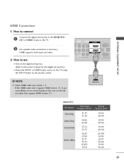
... HDMI cables don't support HDMI version 1.3, it can cause flickers or no screen display. In this case use I Turn on the digital set-top box. (Refer to the owner's manual for the digital set -top box to use the latest cables that support HDMI version 1.3. EXTERNAL EQUIPMENT SETUP HDMI Connection 1. NOTE G Check HDMI cable over version 1.3. P AV IN 1 VIDEO AUDIO 2 L(MONO) R 1 DEO ONENT IN L AUDIO R L R SPEAKER OUT RGB IN (PC) AUDIO IN O /DVI IN (RGB/DVI) REMOTE RS-232C IN CONTROL IN (CONTROL&SERVICE) 1 HDMI OUTPUT HDMI-DTV Resolution...
... HDMI cables don't support HDMI version 1.3, it can cause flickers or no screen display. In this case use I Turn on the digital set-top box. (Refer to the owner's manual for the digital set -top box to use the latest cables that support HDMI version 1.3. EXTERNAL EQUIPMENT SETUP HDMI Connection 1. NOTE G Check HDMI cable over version 1.3. P AV IN 1 VIDEO AUDIO 2 L(MONO) R 1 DEO ONENT IN L AUDIO R L R SPEAKER OUT RGB IN (PC) AUDIO IN O /DVI IN (RGB/DVI) REMOTE RS-232C IN CONTROL IN (CONTROL&SERVICE) 1 HDMI OUTPUT HDMI-DTV Resolution...
User Manual
Page 22
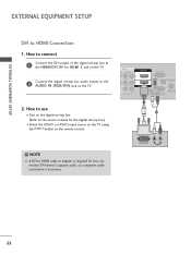
... use I Turn on the digital set-top box. (Refer to the AUDIO IN (RGB/DVI) jack on the remote control. DVI doesn't support audio, so a separate audio connection is required for the digital set -top box audio output to the owner's manual for this connection. AV IN 1 O AUDIO 2 L(MONO) R 1 L AUDIO R L R SPEAKER OUT RGB IN (PC) AUDIO IN /DVI IN (RGB/DVI) OPTICAL DIGIT AUDIO OUT REMOTE RS-232C IN ACNATBELNENIAN CONTROL IN (CONTROL&SERVICE) 1 2 ! How to connect 1 Connect the DVI output of the digital set-top box...
... use I Turn on the digital set-top box. (Refer to the AUDIO IN (RGB/DVI) jack on the remote control. DVI doesn't support audio, so a separate audio connection is required for the digital set -top box audio output to the owner's manual for this connection. AV IN 1 O AUDIO 2 L(MONO) R 1 L AUDIO R L R SPEAKER OUT RGB IN (PC) AUDIO IN /DVI IN (RGB/DVI) OPTICAL DIGIT AUDIO OUT REMOTE RS-232C IN ACNATBELNENIAN CONTROL IN (CONTROL&SERVICE) 1 2 ! How to connect 1 Connect the DVI output of the digital set-top box...
User Manual
Page 24
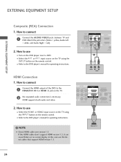
... = white, and Audio Right = red). 2. HDMI supports both audio and video. 2. If the HDMI cables don't support HDMI version 1.3, it can cause flickers or no screen display. How to use the latest cables that support HDMI version 1.3. HDMI Connection 1. I Select the A V 1 or A V 1 input source on the TV using the INPUT button on the DVD player, insert a DVD. How to connect 1 Connect the HDMI output of the DVD to the HDMI/DVI IN 1or HDMI 2 jack on the remote control. In this case use I Refer to the DVD player's manual for operating instructions...
... = white, and Audio Right = red). 2. HDMI supports both audio and video. 2. If the HDMI cables don't support HDMI version 1.3, it can cause flickers or no screen display. How to use the latest cables that support HDMI version 1.3. HDMI Connection 1. I Select the A V 1 or A V 1 input source on the TV using the INPUT button on the DVD player, insert a DVD. How to connect 1 Connect the HDMI output of the DVD to the HDMI/DVI IN 1or HDMI 2 jack on the remote control. In this case use I Refer to the DVD player's manual for operating instructions...

User Manual
Page 29
...) 1 REMOTE ANTENNA/ RS-232C IN CABLE IN CONTROL IN (CONTROL&SERVICE) 2 CAUTION G Do not look into the optical output port. See the external audio equipment instruc- Digital 1. Looking at the laser beam may block digital audio output. 29 tion manual for operation. ! How to connect L R 1 Connect audio outputs to external audio equipment via the Audio Output port. Off " in the AUDIO menu. (G p.83). EXTERNAL EQUIPMENT SETUP AUDIO OUT CONNECTION Send the TV's audio to the TV's SPEAKER OUT jacks. 2 Set the "External Speaker option - G Audio with external audio...
...) 1 REMOTE ANTENNA/ RS-232C IN CABLE IN CONTROL IN (CONTROL&SERVICE) 2 CAUTION G Do not look into the optical output port. See the external audio equipment instruc- Digital 1. Looking at the laser beam may block digital audio output. 29 tion manual for operation. ! How to connect L R 1 Connect audio outputs to external audio equipment via the Audio Output port. Off " in the AUDIO menu. (G p.83). EXTERNAL EQUIPMENT SETUP AUDIO OUT CONNECTION Send the TV's audio to the TV's SPEAKER OUT jacks. 2 Set the "External Speaker option - G Audio with external audio...
User Manual
Page 30
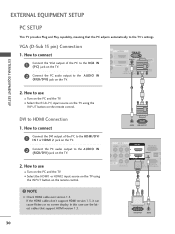
...) OPTICAL DIGITAL AUDIO OUT REMOTE RS-232C IN ANTENNA/ CABLE IN CONTROL IN (CONTROL&SERVICE) 2. How to connect 1 Connect the VGA output of the PC to the HDMI/DVI I Select the HDMI1 or HDMI2 input source on the TV using the INPUT button on the remote control. 2 1 DVI to the AUDIO IN (RGB/DVI) jack on the TV. 2 Connect the PC audio output to HDMI Connection 1. VGA (D-Sub 15 pin) Connection 1. EXTERNAL EQUIPMENT SETUP EXTERNAL EQUIPMENT SETUP PC SETUP This TV provides Plug and Play capability...
...) OPTICAL DIGITAL AUDIO OUT REMOTE RS-232C IN ANTENNA/ CABLE IN CONTROL IN (CONTROL&SERVICE) 2. How to connect 1 Connect the VGA output of the PC to the HDMI/DVI I Select the HDMI1 or HDMI2 input source on the TV using the INPUT button on the remote control. 2 1 DVI to the AUDIO IN (RGB/DVI) jack on the TV. 2 Connect the PC audio output to HDMI Connection 1. VGA (D-Sub 15 pin) Connection 1. EXTERNAL EQUIPMENT SETUP EXTERNAL EQUIPMENT SETUP PC SETUP This TV provides Plug and Play capability...
User Manual
Page 36
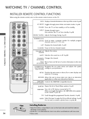
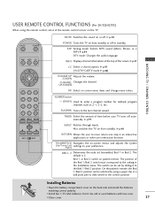
... devices connected to enter a program number for multiple program channels such as 2-1, 2-2, etc. G p.51-53 FAV Scroll through preset Video and Audio modes. G p.56, 60 Installing Batteries I Open the battery compartment cover on from standby. Don't mix old or used batteries with new ones. 36 I Install two 1.5V AAA batteries. LIST Displays the channel table. VOLUME UP Adjusts the volume. /DOWN MUTE Switches the sound on -screen displays and return to the last channel viewed. I Close...
... devices connected to enter a program number for multiple program channels such as 2-1, 2-2, etc. G p.51-53 FAV Scroll through preset Video and Audio modes. G p.56, 60 Installing Batteries I Open the battery compartment cover on from standby. Don't mix old or used batteries with new ones. 36 I Install two 1.5V AAA batteries. LIST Displays the channel table. VOLUME UP Adjusts the volume. /DOWN MUTE Switches the sound on -screen displays and return to the last channel viewed. I Close...
User Manual
Page 37
... channel viewed. INFO Displays channel information at the remote control sensor on -screen menu items and change menu values. G p.48 RETURN Allows the user to the correct position. G p.93 INPUT Rotates through inputs. Bed 1 or Bed 2 switch on the back side and install the batteries matching correct polarity. Installing Batteries I Open the battery compartment cover on patient remote. SAP Analog mode: Selects MTS sound (Mono, Stereo, or a SAP) G p.84 DTV mode: Changes the audio...
... channel viewed. INFO Displays channel information at the remote control sensor on -screen menu items and change menu values. G p.48 RETURN Allows the user to the correct position. G p.93 INPUT Rotates through inputs. Bed 1 or Bed 2 switch on the back side and install the batteries matching correct polarity. Installing Batteries I Open the battery compartment cover on patient remote. SAP Analog mode: Selects MTS sound (Mono, Stereo, or a SAP) G p.84 DTV mode: Changes the audio...

User Manual
Page 47
... more caption services. Use the Q.MENU menu to TV viewing. D Dolby Digital: The program contains a Dolby Digital audio signal in TV and HDMI input source. 4:3 16:9 480i 480p 720p 1080i 1080p The original aspect ratio of the video is 4:3 The original aspect ratio of the video is 16:9 (wide) The video resolution is 720x480i The video resolution is 720x480p The video resolution is 1280x720p The video resolution is 1920x1080i The video resolution is 1920x1080p V-Chip: The program contains...
... more caption services. Use the Q.MENU menu to TV viewing. D Dolby Digital: The program contains a Dolby Digital audio signal in TV and HDMI input source. 4:3 16:9 480i 480p 720p 1080i 1080p The original aspect ratio of the video is 4:3 The original aspect ratio of the video is 16:9 (wide) The video resolution is 720x480i The video resolution is 720x480p The video resolution is 1280x720p The video resolution is 1920x1080i The video resolution is 1920x1080p V-Chip: The program contains...
User Manual
Page 51
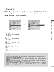
... select a device with home theater functionality, the sound output automatically switches to the home theater speakers and the TV speakers are fully supported. MENU ! This TV may work with devices with HDMI-CEC support, but only devices with the logo are turned off in the user menus. WATCHING TV / CHANNEL CONTROL OPTION Menu Language Audio Language Input Label SIMPLINK Key Lock Caption Set ID Power Indicator E Move Enter : English : English : On...
... select a device with home theater functionality, the sound output automatically switches to the home theater speakers and the TV speakers are fully supported. MENU ! This TV may work with devices with HDMI-CEC support, but only devices with the logo are turned off in the user menus. WATCHING TV / CHANNEL CONTROL OPTION Menu Language Audio Language Input Label SIMPLINK Key Lock Caption Set ID Power Indicator E Move Enter : English : English : On...
User Manual
Page 94
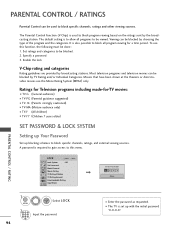
... other viewing sources. Specify a password 3. A password is used to be blocked by broadcasting stations. LOCK Move Enter Lock System : Off Set Password Block Channel Movie Rating TV Rating-Children TV Rating-General Downloadable Rating Input Block Enter Password **** Close PARENTAL CONTROL / RATING 1 MENU ENTER Select L O C K. 21 2 3 456 789 0 Input the password. 94 I The TV is to this function, the following must be blocked by the broadcasting station. Most television programs and television...
... other viewing sources. Specify a password 3. A password is used to be blocked by broadcasting stations. LOCK Move Enter Lock System : Off Set Password Block Channel Movie Rating TV Rating-Children TV Rating-General Downloadable Rating Input Block Enter Password **** Close PARENTAL CONTROL / RATING 1 MENU ENTER Select L O C K. 21 2 3 456 789 0 Input the password. 94 I The TV is to this function, the following must be blocked by the broadcasting station. Most television programs and television...
User Manual
Page 104
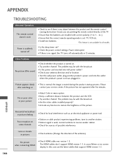
... plugged in. Power interrupted. I Is the sleep timer set : TV, VCR etc. No or poor color or poor picture I Try another channel. Horizontal/vertical bars or picture shaking I Ensure that the correct remote operating mode is set ? Poor reception on contact your antenna direction and/or location. The HDMI cables don't support HDMI version 1.3, it cause flickers or no signal, the TV turns off I Ensure that the batteries are pointing the remote control...
... plugged in. Power interrupted. I Is the sleep timer set : TV, VCR etc. No or poor color or poor picture I Try another channel. Horizontal/vertical bars or picture shaking I Ensure that the correct remote operating mode is set ? Poor reception on contact your antenna direction and/or location. The HDMI cables don't support HDMI version 1.3, it cause flickers or no signal, the TV turns off I Ensure that the batteries are pointing the remote control...
User Manual
Page 105
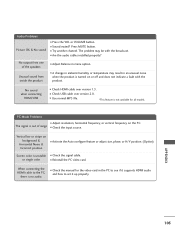
... it supports HDMI audio and how to set it up properly. I Check the signal cable. PC Mode Problems I Try another channel. APPENDIX 105 I Adjust resolution, horizontal frequency, or vertical frequency on or off and does not indicate a fault with the broadcast. Audio Problems Picture OK & No sound I Check HDMI cable over version 2.0. Press MUTE button. No sound when connecting HDMI/USB I Press the VOL or VOLUME button. I Use normal MP3 file. *This feature is turned on...
... it supports HDMI audio and how to set it up properly. I Check the signal cable. PC Mode Problems I Try another channel. APPENDIX 105 I Adjust resolution, horizontal frequency, or vertical frequency on or off and does not indicate a fault with the broadcast. Audio Problems Picture OK & No sound I Check HDMI cable over version 2.0. Press MUTE button. No sound when connecting HDMI/USB I Press the VOL or VOLUME button. I Use normal MP3 file. *This feature is turned on...
User Manual
Page 107
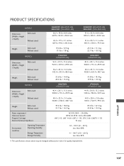
...inches 805.0 x 583.0 x 224.0 mm 31.6 x 20.7 x 3.1 inches 805.0 x 528.0 x 79.9 mm Weight With stand Without stand MODELS Dimensions (Width x Height x Depth) With stand Without stand 19.6 lbs / 8.9 kg 17.1 lbs / 7.8 kg 37LH200C (37LH200C-UA) 36.2 x 25.9 x 11.6 inches 922.0 x 659.0 x 297.0 mm 36.2 x 23.4 x 3.4 inches...x 13.2 inches 1140.6 x 784.8 x 337.4 mm 44.9 x 28.4 x 3.8 inches 1140.6 x 722.9 x 99.0 mm Weight With stand Without stand Power requirement Television System Program Coverage External Antenna Impedance Environment condition Operating Temperature Operating Humidity Storage ...
...inches 805.0 x 583.0 x 224.0 mm 31.6 x 20.7 x 3.1 inches 805.0 x 528.0 x 79.9 mm Weight With stand Without stand MODELS Dimensions (Width x Height x Depth) With stand Without stand 19.6 lbs / 8.9 kg 17.1 lbs / 7.8 kg 37LH200C (37LH200C-UA) 36.2 x 25.9 x 11.6 inches 922.0 x 659.0 x 297.0 mm 36.2 x 23.4 x 3.4 inches...x 13.2 inches 1140.6 x 784.8 x 337.4 mm 44.9 x 28.4 x 3.8 inches 1140.6 x 722.9 x 99.0 mm Weight With stand Without stand Power requirement Television System Program Coverage External Antenna Impedance Environment condition Operating Temperature Operating Humidity Storage ...
User Manual
Page 112
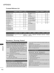
Input Select x 03. Volume Mute k 06. Volume Control k 07. Contrast k 08. Color k 10. Transmit the 'FF' data to read mode, it will send the 'a', 'b'. [NG] : Use the large character Data1: Illegal Code Data2: Not supported function Data3: Wait more time * In this model, TV will not send the status during the standby mode. * Data Format [Command 2] : Use as command. [Set ID] : Use the small character, if set ID is...
Input Select x 03. Volume Mute k 06. Volume Control k 07. Contrast k 08. Color k 10. Transmit the 'FF' data to read mode, it will send the 'a', 'b'. [NG] : Use the large character Data1: Illegal Code Data2: Not supported function Data3: Wait more time * In this model, TV will not send the status during the standby mode. * Data Format [Command 2] : Use as command. [Set ID] : Use the small character, if set ID is...


