Owner's Manual (English)
Page 6
... 18 DVD Setup 21 VCR Setup 23 Other A/V Source Setup 25 PC Setup 26 Audio Out Setup 31 WATCHING TV / CHANNEL CONTROL Remote Control Functions 32 Turning On TV 34 Channel Selection 34 Volume Adjustment 34 On-Screen Menus Selection 35 Channel Setup - Auto Scan (Auto Tuning 36... - Picture Mode - Add / Delete Channel (Manual Tuning 37 - Channel Editing 38 Input List 39 SimpLink 40 Input Label 42 Key Lock ...
... 18 DVD Setup 21 VCR Setup 23 Other A/V Source Setup 25 PC Setup 26 Audio Out Setup 31 WATCHING TV / CHANNEL CONTROL Remote Control Functions 32 Turning On TV 34 Channel Selection 34 Volume Adjustment 34 On-Screen Menus Selection 35 Channel Setup - Auto Scan (Auto Tuning 36... - Picture Mode - Add / Delete Channel (Manual Tuning 37 - Channel Editing 38 Input List 39 SimpLink 40 Input Label 42 Key Lock ...
Owner's Manual (English)
Page 7
Auto Clock Setup 67 Manual Clock Setup 68 Auto On/Off Timer Setting 69 Sleep Timer Setting 70 Auto Shut-off Setting 71 PARENTAL CONTROL / RATINGS Set Password & Lock System 72 Channel Blocking 74 External Input Blocking 74 Movie & TV Rating 75 APPENDIX Troubleshooting 78 Maintenance 80 Product Specifications 81 Programming the Remote Control 83 IR Codes 87 External Control Through RS-232C 89 Open Source License 96 5 TIME SETTING Clock Setting -
Auto Clock Setup 67 Manual Clock Setup 68 Auto On/Off Timer Setting 69 Sleep Timer Setting 70 Auto Shut-off Setting 71 PARENTAL CONTROL / RATINGS Set Password & Lock System 72 Channel Blocking 74 External Input Blocking 74 Movie & TV Rating 75 APPENDIX Troubleshooting 78 Maintenance 80 Product Specifications 81 Programming the Remote Control 83 IR Codes 87 External Control Through RS-232C 89 Open Source License 96 5 TIME SETTING Clock Setting -
Owner's Manual (English)
Page 8
... special digital image generator, consisting of SRS Labs, Inc. is nothing wrong with one remote control. FOR LCD TV I If the TV feels cold to the HDMI (high-definition multimedia interface), LG TV with this product with one cable and produces the highest quality digital images and sound. Do not dispose of digital television, HDTV formats...
... special digital image generator, consisting of SRS Labs, Inc. is nothing wrong with one remote control. FOR LCD TV I If the TV feels cold to the HDMI (high-definition multimedia interface), LG TV with this product with one cable and produces the highest quality digital images and sound. Do not dispose of digital television, HDTV formats...
Owner's Manual (English)
Page 9
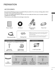
ENU ENTER RATIO SIMPLINK CH BRIGHT + TV INPUT TV AUDIO POWER CAMBOLEDDVED INPUT VCR STB BRIGHT - TV Bracket Bolts 2- CD Manual 1 4 7 Remote Control, Batteries Power Cord 75ohm Round Cable Polishing Cloth * Slightly wipe stained spot on surface of that the following accessories ...) with the polishing cloth for the product. For Plasma TV models This feature is not available for all models 32/37 inches only Cable Management 2- TV Brackets, Twist Holder (Refer to p.16) D-sub 15 pin Cable For LCD TV models This feature is not available for all models Option Extras...
ENU ENTER RATIO SIMPLINK CH BRIGHT + TV INPUT TV AUDIO POWER CAMBOLEDDVED INPUT VCR STB BRIGHT - TV Bracket Bolts 2- CD Manual 1 4 7 Remote Control, Batteries Power Cord 75ohm Round Cable Polishing Cloth * Slightly wipe stained spot on surface of that the following accessories ...) with the polishing cloth for the product. For Plasma TV models This feature is not available for all models 32/37 inches only Cable Management 2- TV Brackets, Twist Holder (Refer to p.16) D-sub 15 pin Cable For LCD TV models This feature is not available for all models Option Extras...
Owner's Manual (English)
Page 10
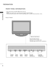
Plasma TV Model PREPARATION Remote Control Sensor Power/Standby Indicator Illuminates red in standby mode. Illuminates green when the set is included with your product, use it). I Here shown may be somewhat different from your TV. INPUT MENU ENTER VOL CH INPUT MENU ENTER VOL CH POWER Button INPUT Button MENU Button ENTER Button VOLUME (F,G)Buttons CHANNEL (E,D)Buttons 8 And then wipe the product with a cloth (If a polishing cloth is switched on. PREPARATION FRONT PANEL INFORMATION I NOTE: If your product has a protection tape attached, remove the tape.
Plasma TV Model PREPARATION Remote Control Sensor Power/Standby Indicator Illuminates red in standby mode. Illuminates green when the set is included with your product, use it). I Here shown may be somewhat different from your TV. INPUT MENU ENTER VOL CH INPUT MENU ENTER VOL CH POWER Button INPUT Button MENU Button ENTER Button VOLUME (F,G)Buttons CHANNEL (E,D)Buttons 8 And then wipe the product with a cloth (If a polishing cloth is switched on. PREPARATION FRONT PANEL INFORMATION I NOTE: If your product has a protection tape attached, remove the tape.
Owner's Manual (English)
Page 11
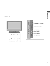
CH VOL ENTER MENU INPUT CH VOL ENTER MENU INPUT CHANNEL (D,E)Buttons VOLUME (F,G)Buttons ENTER Button MENU Button INPUT Button POWER Button 9 Illuminates green when the set is switched on. PREPARATION LCD TV Model Remote Control Sensor Power/Standby Indicator Illuminates red in standby mode.
CH VOL ENTER MENU INPUT CH VOL ENTER MENU INPUT CHANNEL (D,E)Buttons VOLUME (F,G)Buttons ENTER Button MENU Button INPUT Button POWER Button 9 Illuminates green when the set is switched on. PREPARATION LCD TV Model Remote Control Sensor Power/Standby Indicator Illuminates red in standby mode.
Owner's Manual (English)
Page 13
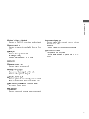
... & SERVICE) PORT For external control devices. 9 AUDIO OUT Connect analog audio to various types of equipment. S-VIDEO Connect S-Video out from a PC or DTV. 4 SERVICE 5 Remote Control Port Connect a wired remote control. 6 ANTENNA/CABLE IN Connect over-the air signals to operate the...
... & SERVICE) PORT For external control devices. 9 AUDIO OUT Connect analog audio to various types of equipment. S-VIDEO Connect S-Video out from a PC or DTV. 4 SERVICE 5 Remote Control Port Connect a wired remote control. 6 ANTENNA/CABLE IN Connect over-the air signals to operate the...
Owner's Manual (English)
Page 20
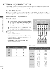
...top box. However, if you have finished connecting all equipment. VIDEO AUDIO S-V ( /DVI IN 2. HD RECEIVER SETUP This TV can receive Digital Over-the-air/Cable signals without an external digital set-top box. How to connect 1 Connect the video .../DVI) SERVICE CONT COMPONENT IN 2 RS (CONTR 2 Connect the audio output of EXTERNAL EQUIPMENT SETUP mainly use I Turn on the remote control. 1 2 I This part of the digital set-top box to the COMPONENT IN VIDEO 1 jacks on the set. EXTERNAL...-top box or other digital external device, refer to the owner's manual for LCD TV model.
...top box. However, if you have finished connecting all equipment. VIDEO AUDIO S-V ( /DVI IN 2. HD RECEIVER SETUP This TV can receive Digital Over-the-air/Cable signals without an external digital set-top box. How to connect 1 Connect the video .../DVI) SERVICE CONT COMPONENT IN 2 RS (CONTR 2 Connect the audio output of EXTERNAL EQUIPMENT SETUP mainly use I Turn on the remote control. 1 2 I This part of the digital set-top box to the COMPONENT IN VIDEO 1 jacks on the set. EXTERNAL...-top box or other digital external device, refer to the owner's manual for LCD TV model.
Owner's Manual (English)
Page 21
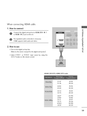
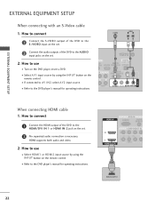
... HDMI/DVI IN 1 or HDMI IN 2 jack on the set -top box.) I Select HDMI1 or HDMI2 input source by using the INPUT button on the remote control. EXTERNAL EQUIPMENT SETUP When connecting HDMI cable 1.
... HDMI/DVI IN 1 or HDMI IN 2 jack on the set -top box.) I Select HDMI1 or HDMI2 input source by using the INPUT button on the remote control. EXTERNAL EQUIPMENT SETUP When connecting HDMI cable 1.
Owner's Manual (English)
Page 22
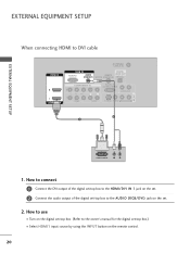
... set-top box.) I Select HDMI1 input source by using the INPUT button on the set -top box to the AUDIO (RGB/DVI) jack on the remote control. 20 How to connect 1 Connect the DVI output of the digital set-top box to DVI cable HDMI IN ANTENNA/ CABLE IN RGB IN... DIGITAL RGB(PC) AUDIO REMOTE AUDIO OUT (RGB/DVI) SERVICE CONTROL IN OPTICAL 2 2 1 1 HDMI/DVI IN COMPONENT IN RS-232C IN (CONTROL & SERVICE) AUDIO OUT VIDEO AUDIO S-VIDEO VIDEO (MONO...
... set-top box.) I Select HDMI1 input source by using the INPUT button on the set -top box to the AUDIO (RGB/DVI) jack on the remote control. 20 How to connect 1 Connect the DVI output of the digital set-top box to DVI cable HDMI IN ANTENNA/ CABLE IN RGB IN... DIGITAL RGB(PC) AUDIO REMOTE AUDIO OUT (RGB/DVI) SERVICE CONTROL IN OPTICAL 2 2 1 1 HDMI/DVI IN COMPONENT IN RS-232C IN (CONTROL & SERVICE) AUDIO OUT VIDEO AUDIO S-VIDEO VIDEO (MONO...
Owner's Manual (English)
Page 23
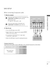
... = red). How to connect EXTERNAL EQUIPMENT SETUP 1 Connect the video outputs (Y, PB, PR) of the DVD to the COMPONENT IN AUDIO1 jacks on the remote control. RGB IN RGB(PC) AUDIO REM (RGB/DVI) SERVICE CONT 2 Connect the audio outputs of the DVD to use 1 VI IN VIDEO AUDIO S-...VI ( ) I Select Component 1 input source by using the INPUT button on the set . Component ports on the TV Y PB PR Video output ports on the set . How to the COMPONENT IN VIDEO1 jacks on DVD player Y PB PR Y B-Y R-Y Y Cb Cr Y Pb Pr...
... = red). How to connect EXTERNAL EQUIPMENT SETUP 1 Connect the video outputs (Y, PB, PR) of the DVD to the COMPONENT IN AUDIO1 jacks on the remote control. RGB IN RGB(PC) AUDIO REM (RGB/DVI) SERVICE CONT 2 Connect the audio outputs of the DVD to use 1 VI IN VIDEO AUDIO S-...VI ( ) I Select Component 1 input source by using the INPUT button on the set . Component ports on the TV Y PB PR Video output ports on the set . How to the COMPONENT IN VIDEO1 jacks on DVD player Y PB PR Y B-Y R-Y Y Cb Cr Y Pb Pr...
Owner's Manual (English)
Page 24
...AUDIO AV IN 1 When connecting HDMI cable 1. HDMI suppo( rt)s both audio and video. 2. I If connected to the AUDIO input jacks on the remote control. I Refer to the DVD player's manual for operating instructions. HDMI IN RGB IN RGB(PC) AUDIO (RGB/DVI 2 2 1 1 HDMI/DVI... IN COMPONENT IN VIDEO A 1 HDMI-DVD OUTPUT 22 I Turn on the remote control. How to the S -VIDEO input on the set . 2 No separated audio connection is necessary. EXTERNAL EQUIPMENT SETUP EXTERNAL EQUIPMENT SETUP When connecting ...
...AUDIO AV IN 1 When connecting HDMI cable 1. HDMI suppo( rt)s both audio and video. 2. I If connected to the AUDIO input jacks on the remote control. I Refer to the DVD player's manual for operating instructions. HDMI IN RGB IN RGB(PC) AUDIO (RGB/DVI 2 2 1 1 HDMI/DVI... IN COMPONENT IN VIDEO A 1 HDMI-DVD OUTPUT 22 I Turn on the remote control. How to the S -VIDEO input on the set . 2 No separated audio connection is necessary. EXTERNAL EQUIPMENT SETUP EXTERNAL EQUIPMENT SETUP When connecting ...
Owner's Manual (English)
Page 25
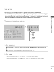
... manufactures warr(ant) y does not cover the product bearing this phenomenon. I To avoid picture noise (interference), leave an adequate distance between the VCR and TV. EXTERNAL EQUIPMENT SETUP VCR SETUP I Insert a video tape into the VCR and press PLAY on the VCR. (Refer to the VCR owner's manual.) 23... ( ) When connecting with an antenna ANTENNA/ CABLE IN GB IN DIGITAL AUDIO REMOTE AUDIO OUT (RGB/DVI) SERVICE CONTROL IN OPTICAL MPONENT IN RS-232C IN (CONTROL & SERVICE) AUDIO OUT EO AUDIO S-VIDEO VIDEO (MONO) AUDIO ...
... manufactures warr(ant) y does not cover the product bearing this phenomenon. I To avoid picture noise (interference), leave an adequate distance between the VCR and TV. EXTERNAL EQUIPMENT SETUP VCR SETUP I Insert a video tape into the VCR and press PLAY on the VCR. (Refer to the VCR owner's manual.) 23... ( ) When connecting with an antenna ANTENNA/ CABLE IN GB IN DIGITAL AUDIO REMOTE AUDIO OUT (RGB/DVI) SERVICE CONTROL IN OPTICAL MPONENT IN RS-232C IN (CONTROL & SERVICE) AUDIO OUT EO AUDIO S-VIDEO VIDEO (MONO) AUDIO ...

Owner's Manual (English)
Page 26
... input source by using the INPUT button on the set. 2. NOTE G The picture quality is improved: compared to connect 1 Connect the AUDIO/VIDEO jacks between TV and VCR. Match the jack colors (Video = yellow, Audio Left = white, and Audio Right = red) 2. ANT IN S-VIDEO VIDEO L R ANT ... RS-232C IN (CONTROL & SERVICE) ( ) AUDIO OUT AUDIO S-VIDEO VIDEO (MONO) AUDIO AV IN 1 ! UDIO B/DVI) ANTENNA/ CABLE IN 1 2 DIGITAL REMOTE AUDIO O( UT) SERVICE CONTROL IN OPTICAL T IN RS-232C IN (CONTROL & SERVICE) AUDIO OUT AV IN 1 AUDIO S-VIDEO VIDEO (MONO) AUDIO CAUTION G Do ...
... input source by using the INPUT button on the set. 2. NOTE G The picture quality is improved: compared to connect 1 Connect the AUDIO/VIDEO jacks between TV and VCR. Match the jack colors (Video = yellow, Audio Left = white, and Audio Right = red) 2. ANT IN S-VIDEO VIDEO L R ANT ... RS-232C IN (CONTROL & SERVICE) ( ) AUDIO OUT AUDIO S-VIDEO VIDEO (MONO) AUDIO AV IN 1 ! UDIO B/DVI) ANTENNA/ CABLE IN 1 2 DIGITAL REMOTE AUDIO O( UT) SERVICE CONTROL IN OPTICAL T IN RS-232C IN (CONTROL & SERVICE) AUDIO OUT AV IN 1 AUDIO S-VIDEO VIDEO (MONO) AUDIO CAUTION G Do ...

Owner's Manual (English)
Page 27
VIDEO L/MONO AUDIO R Camcorder Video Game Set VIDEO L R S-VIDEO 1 AV IN 2 25 I Select A V 2 input source by using the INPUT button on the remote control. How to AV IN1 input, select A V 1 input source. Match the jack colors. (Video = yellow, Audio Left = white, and Audio Right = red) 2. How to use I If connected to connect 1 Connect the AUDIO/VIDEO jacks between TV and external equipment. I Operate the corresponding external equipment. EXTERNAL EQUIPMENT SETUP OTHER A/V SOURCE SETUP 1.
VIDEO L/MONO AUDIO R Camcorder Video Game Set VIDEO L R S-VIDEO 1 AV IN 2 25 I Select A V 2 input source by using the INPUT button on the remote control. How to AV IN1 input, select A V 1 input source. Match the jack colors. (Video = yellow, Audio Left = white, and Audio Right = red) 2. How to use I If connected to connect 1 Connect the AUDIO/VIDEO jacks between TV and external equipment. I Operate the corresponding external equipment. EXTERNAL EQUIPMENT SETUP OTHER A/V SOURCE SETUP 1.
Owner's Manual (English)
Page 28
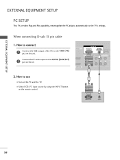
EXTERNAL EQUIPMENT SETUP EXTERNAL EQUIPMENT SETUP PC SETUP This TV provides Plug and Play capability, meaning that the PC adjusts automatically to use I Turn on the remote control. How to connect 1 Connect the RGB output of the PC to the AUDIO (RGB/DVI) 2 jack on the set . 2. Connect the PC ...audio output to the R GB (P C) jack on the set . How to the TV's settings. When connecting D-sub 15 pin ...
EXTERNAL EQUIPMENT SETUP EXTERNAL EQUIPMENT SETUP PC SETUP This TV provides Plug and Play capability, meaning that the PC adjusts automatically to use I Turn on the remote control. How to connect 1 Connect the RGB output of the PC to the AUDIO (RGB/DVI) 2 jack on the set . 2. Connect the PC ...audio output to the R GB (P C) jack on the set . How to the TV's settings. When connecting D-sub 15 pin ...

Owner's Manual (English)
Page 29
... AUDIO (RGB/DVI) jack on the set . 2 Connect the PC audio output to DVI cable CABLE IN HDMI IN RGB IN DIGITAL RGB(PC) AUDIO REMOTE AUDIO OUT (RGB/DVI) SERVICE CONTROL IN OPTICAL 2 2 1 1 HDMI/DVI IN COMPONENT IN RS-232C IN (CONTROL & SERVICE) AUDIO OUT VIDEO AUDIO S-VIDEO VIDEO (MONO...-PC OUTPUT AUDIO 1. How to connect 1 Connect the DVI output of the PC to the HDMI/DVI IN 1 jack on the set . 2. I Turn on the remote control. 27 How to use I Select HDMI1 input source by using the INPUT button on the PC and the...
... AUDIO (RGB/DVI) jack on the set . 2 Connect the PC audio output to DVI cable CABLE IN HDMI IN RGB IN DIGITAL RGB(PC) AUDIO REMOTE AUDIO OUT (RGB/DVI) SERVICE CONTROL IN OPTICAL 2 2 1 1 HDMI/DVI IN COMPONENT IN RS-232C IN (CONTROL & SERVICE) AUDIO OUT VIDEO AUDIO S-VIDEO VIDEO (MONO...-PC OUTPUT AUDIO 1. How to connect 1 Connect the DVI output of the PC to the HDMI/DVI IN 1 jack on the set . 2. I Turn on the remote control. 27 How to use I Select HDMI1 input source by using the INPUT button on the PC and the...
Owner's Manual (English)
Page 31
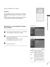
.../down as you select resolution of characters. 29 I The Size adjustment range is -16 ~ +16. For Plasma TV Resolution Position Size 1024 x 768 1280 x 768 1360 x 768 Phase Reset D MENU Prev E Select Ok For LCD TV Resolution Position Size Phase 1024 x 768 1280 x 768 1360 x 768 1366 x 768 Reset D MENU Prev E Select Ok... Output, Select RGB-PC with using the INPUT button on the screen background. When you to remove any vertical bars or stripes visible on the remote control. Size This function is connected to make appropriate adjustments.
.../down as you select resolution of characters. 29 I The Size adjustment range is -16 ~ +16. For Plasma TV Resolution Position Size 1024 x 768 1280 x 768 1360 x 768 Phase Reset D MENU Prev E Select Ok For LCD TV Resolution Position Size Phase 1024 x 768 1280 x 768 1360 x 768 1366 x 768 Reset D MENU Prev E Select Ok... Output, Select RGB-PC with using the INPUT button on the screen background. When you to remove any vertical bars or stripes visible on the remote control. Size This function is connected to make appropriate adjustments.
Owner's Manual (English)
Page 33
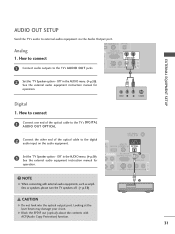
...& SERVICE) AUDIO OUT AV IN 1 1 Connect audio outputs to the digital audio input on the audio equipment. 3 Set the "TV Speaker option - G Block the SPDIF out (optical) about the contents with external audio equipments, such as amplifiers or speakers, please turn the... TV speakers off. (G p.59) ANTENNA/ CABLE IN DIGITAL O REMOTE AUDIO OUT VI) SERVICE CONTROL IN OPTICAL N RS-232C IN 1 (CONTROL & SERVICE) AUDIO OUT AUDIO S-VIDEO VIDEO (MONO) ...
...& SERVICE) AUDIO OUT AV IN 1 1 Connect audio outputs to the digital audio input on the audio equipment. 3 Set the "TV Speaker option - G Block the SPDIF out (optical) about the contents with external audio equipments, such as amplifiers or speakers, please turn the... TV speakers off. (G p.59) ANTENNA/ CABLE IN DIGITAL O REMOTE AUDIO OUT VI) SERVICE CONTROL IN OPTICAL N RS-232C IN 1 (CONTROL & SERVICE) AUDIO OUT AUDIO S-VIDEO VIDEO (MONO) ...
Owner's Manual (English)
Page 34
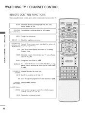
.... BACK Tune to enter a program number for multiple program channels such as 2-1, 2-2, etc. WATCHING TV / CHANNEL CONTROL WATCHING TV / CHANNEL CONTROL REMOTE CONTROL FUNCTIONS When using the remote control, aim it at the screen. EXIT Clear all on screen. G p.44 SIMPLINK See a ...G p.38 CHANNEL Select available channels. When you toggle this button, the SimpLink menu appears at the remote control sensor on -screen menus and adjust the system set- (Up/Down/Left Right/ENTER) tings to TV viewing from any menu. MENU BRIGHT + ENTER EXIT TIMER RATIO SIMPLINK VOL MUTE FAV CH 1 2...
.... BACK Tune to enter a program number for multiple program channels such as 2-1, 2-2, etc. WATCHING TV / CHANNEL CONTROL WATCHING TV / CHANNEL CONTROL REMOTE CONTROL FUNCTIONS When using the remote control, aim it at the screen. EXIT Clear all on screen. G p.44 SIMPLINK See a ...G p.38 CHANNEL Select available channels. When you toggle this button, the SimpLink menu appears at the remote control sensor on -screen menus and adjust the system set- (Up/Down/Left Right/ENTER) tings to TV viewing from any menu. MENU BRIGHT + ENTER EXIT TIMER RATIO SIMPLINK VOL MUTE FAV CH 1 2...


