
User Manual
Page 6
... HD Receiver Setup 17 DVD Setup 20 VCR Setup 22 Other A/V Source Setup 24 Pillow Speaker Setup 25 PC Setup 26 WATCHING TV / CHANNEL CONTROL Remote Control Functions 32 Turning On TV 34 Channel Selection 35 Volume Adjustment 35 On-Screen Menus Selection 36 Channel Setup -
... HD Receiver Setup 17 DVD Setup 20 VCR Setup 22 Other A/V Source Setup 24 Pillow Speaker Setup 25 PC Setup 26 WATCHING TV / CHANNEL CONTROL Remote Control Functions 32 Turning On TV 34 Channel Selection 35 Volume Adjustment 35 On-Screen Menus Selection 36 Channel Setup -

User Manual
Page 9
...INPUT RATIO 7 5 3 - 8 6 0 9 ADJUST ENTER VOL TIMER CC MUTE MENU CH RETURN FLASHBK 1.5V 1.5V Remote Control, Batteries (only 32LG3DC model) Power Cord x4 x4 Bolts for stand assembly (Refer to P.11) (only 32LG3DC model) Protective Bracket and Bolt for Power Cord (Refer to P.12) Screw for stand fixing (Refer to...32LG3DCH Shown herein is NOT included with the TV. * Wipe spots on the exterior only with ferrite cores to P.14) Optional Installer Remote Control for all models.) Option Extras D-sub 15 pin Cable When using the VGA (D-sub 15 pin cable) PC connection, the user...
...INPUT RATIO 7 5 3 - 8 6 0 9 ADJUST ENTER VOL TIMER CC MUTE MENU CH RETURN FLASHBK 1.5V 1.5V Remote Control, Batteries (only 32LG3DC model) Power Cord x4 x4 Bolts for stand assembly (Refer to P.11) (only 32LG3DC model) Protective Bracket and Bolt for Power Cord (Refer to P.12) Screw for stand fixing (Refer to...32LG3DCH Shown herein is NOT included with the TV. * Wipe spots on the exterior only with ferrite cores to P.14) Optional Installer Remote Control for all models.) Option Extras D-sub 15 pin Cable When using the VGA (D-sub 15 pin cable) PC connection, the user...

User Manual
Page 10
Illuminates blue when the set is not available for all models 32LG3DC model Power/Standby Indicator Illuminates red in standby mode. Remote Control Sensor POWER Button 26/32LG3DCH model Power/Standby Indicator Illuminates red in standby mode. And then wipe ...tape attached, remove the tape. PREPARATION CHANNEL(+, -) CH Buttons Stand (only 32LG3DC model) :This feature is switched on . Illuminates green when the set is included with a cloth (If a polishing cloth is switched on . Remote Control Sensor POWER Button VOL ENTER MENU INPUT VOLUME (+, -) Buttons ENTER Button...
Illuminates blue when the set is not available for all models 32LG3DC model Power/Standby Indicator Illuminates red in standby mode. Remote Control Sensor POWER Button 26/32LG3DCH model Power/Standby Indicator Illuminates red in standby mode. And then wipe ...tape attached, remove the tape. PREPARATION CHANNEL(+, -) CH Buttons Stand (only 32LG3DC model) :This feature is switched on . Illuminates green when the set is included with a cloth (If a polishing cloth is switched on . Remote Control Sensor POWER Button VOL ENTER MENU INPUT VOLUME (+, -) Buttons ENTER Button...

User Manual
Page 11
BACK PANEL INFORMATION I Image shown may differ from your TV. PREPARATION 11 12 1 AV IN 2 SPEAKER SWITCH UPDATE RESET HDMI/DVI IN USB IN SERVUCE ONLY RS-232C IN (SERVICE ONLY) PILLOW NORMAL SPEAKER SPEAKER AUDIO (MONO) VIDEO RGB IN (PC) PILLOW SPEAKER VIDEO AUDIO AUDIO IN (RGB/DVI) REMOTE SPEAKER OUT CONTROL OUT 8 ( ) VIDEO L/MONO AUDIO R H/P R PILLOW NORMAL SPEAKER SPEAKER PILLOW SPEAKER 9 S-VIDEO COMPONENT AV IN 1 IN
BACK PANEL INFORMATION I Image shown may differ from your TV. PREPARATION 11 12 1 AV IN 2 SPEAKER SWITCH UPDATE RESET HDMI/DVI IN USB IN SERVUCE ONLY RS-232C IN (SERVICE ONLY) PILLOW NORMAL SPEAKER SPEAKER AUDIO (MONO) VIDEO RGB IN (PC) PILLOW SPEAKER VIDEO AUDIO AUDIO IN (RGB/DVI) REMOTE SPEAKER OUT CONTROL OUT 8 ( ) VIDEO L/MONO AUDIO R H/P R PILLOW NORMAL SPEAKER SPEAKER PILLOW SPEAKER 9 S-VIDEO COMPONENT AV IN 1 IN
User Manual
Page 12
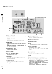
... signals to this jack. 14 M.P. Connect over -the air signals to these jacks. 9 10 8 AUDIO IN (RGB/DVI) Connect the audio from a PC or DTV. 9 REMOTE CONTROL OUT 10 SPEAKER OUT 8Ω 11 H/P Plug the headphone into the headphone socket. 12 Power Cord Socket For operation with AC power. Note: If...(SERVICE ONLY) 5 PILLOW SPEAKER NORMAL SPEAKER AUDIO (MONO) VIDEO RGB IN (PC) S-VIDEO COMPONENT AV IN 1 PILLOW SPEAKER 1 6 ( ) 8 IN 7 VIDEO AUDIO AUDIO IN (RGB/DVI) REMOTE SPEAKER OUT CONTROL OUT 8 1 AV (Audio/Video) IN Connect audio/video output from TV speakers.
... signals to this jack. 14 M.P. Connect over -the air signals to these jacks. 9 10 8 AUDIO IN (RGB/DVI) Connect the audio from a PC or DTV. 9 REMOTE CONTROL OUT 10 SPEAKER OUT 8Ω 11 H/P Plug the headphone into the headphone socket. 12 Power Cord Socket For operation with AC power. Note: If...(SERVICE ONLY) 5 PILLOW SPEAKER NORMAL SPEAKER AUDIO (MONO) VIDEO RGB IN (PC) S-VIDEO COMPONENT AV IN 1 PILLOW SPEAKER 1 6 ( ) 8 IN 7 VIDEO AUDIO AUDIO IN (RGB/DVI) REMOTE SPEAKER OUT CONTROL OUT 8 1 AV (Audio/Video) IN Connect audio/video output from TV speakers.

User Manual
Page 19
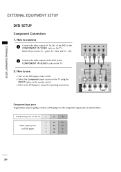
... receive Digital Over-the-air/Cable signals without an external digital set -top box.) I Select Component input source with using the INPUT button on the remote control. COMPONENT AV IN 1 IN S-VIDEO Y PB PR L R 1 HDMI/DVI IN UPDATE 2 RESET USB IN SERVUCE ONLY RS-232C IN (SERVICE... (Y = green, PB = blue, and PR = red). 2 Connect the audio output of the digital settop box to the owner's manual for 32LG3DC model. How to use picture for the digital set -top box. EXTERNAL EQUIPMENT SETUP Component Connection 1. However, if you have finished connecting all equipment.
... receive Digital Over-the-air/Cable signals without an external digital set -top box.) I Select Component input source with using the INPUT button on the remote control. COMPONENT AV IN 1 IN S-VIDEO Y PB PR L R 1 HDMI/DVI IN UPDATE 2 RESET USB IN SERVUCE ONLY RS-232C IN (SERVICE... (Y = green, PB = blue, and PR = red). 2 Connect the audio output of the digital settop box to the owner's manual for 32LG3DC model. How to use picture for the digital set -top box. EXTERNAL EQUIPMENT SETUP Component Connection 1. However, if you have finished connecting all equipment.

User Manual
Page 20
... connect 1 Connect the digital set-top box to the owner's manual for the digital set -top box. (Refer to HDMI/DVI IN jack on the remote control. ( ) COMPONENT IN AV IN 1 S-VIDEO HDMI/DVI IN UPDATE USB IN SERVUCE ONL AUDIO (MONO) VIDEO 1 VIDEO AU HDMI-DTV OUTPUT HDMI-DTV Resolution...
... connect 1 Connect the digital set-top box to the owner's manual for the digital set -top box. (Refer to HDMI/DVI IN jack on the remote control. ( ) COMPONENT IN AV IN 1 S-VIDEO HDMI/DVI IN UPDATE USB IN SERVUCE ONL AUDIO (MONO) VIDEO 1 VIDEO AU HDMI-DTV OUTPUT HDMI-DTV Resolution...

User Manual
Page 21
... set-top box.) I Turn on the digital set-top box. (Refer to the AUDIO IN(RGB/DVI) jack on the remote control. ! EXTERNAL EQUIPMENT SETUP ( ) RGB IN (PC) AUDIO IN (RGB/DVI) REMOTE SPEAKER OUT CONTROL OUT 8 DVI to HDMI cable or adapter is necessary. NOTE G A DVI to HDMI Connection 1. How to...
... set-top box.) I Turn on the digital set-top box. (Refer to the AUDIO IN(RGB/DVI) jack on the remote control. ! EXTERNAL EQUIPMENT SETUP ( ) RGB IN (PC) AUDIO IN (RGB/DVI) REMOTE SPEAKER OUT CONTROL OUT 8 DVI to HDMI cable or adapter is necessary. NOTE G A DVI to HDMI Connection 1. How to...
User Manual
Page 22
... use I Refer to the COMPONENT IN AUDIO jacks on the TV. 2. I Turn on the TV. Component ports on the TV Y Y Video output ports Y on the remote control. I Select the Component input source on the TV using the INPUT button on DVD player Y Y PB PR PB PR B-Y R-Y Cb Cr Pb Pr 20...
... use I Refer to the COMPONENT IN AUDIO jacks on the TV. 2. I Turn on the TV. Component ports on the TV Y Y Video output ports Y on the remote control. I Select the Component input source on the TV using the INPUT button on DVD player Y Y PB PR PB PR B-Y R-Y Cb Cr Pb Pr 20...

User Manual
Page 23
I Select the A V 1 input source on the TV using the INPUT button on the remote control. How to use I Refer to the AUDIO input jacks on the TV. 2 No separate audio connection is necessary. I Select the HDMI/DVI input source ... to the S -VIDEO input on the TV. 2 Connect the audio outputs of the DVD to the DVD player's manual for operating instructions. I Turn on the remote control.
I Select the A V 1 input source on the TV using the INPUT button on the remote control. How to use I Refer to the AUDIO input jacks on the TV. 2 No separate audio connection is necessary. I Select the HDMI/DVI input source ... to the S -VIDEO input on the TV. 2 Connect the audio outputs of the DVD to the DVD player's manual for operating instructions. I Turn on the remote control.

User Manual
Page 25
...both Video and S-Video at the same time. S-Video Connection 1. I Select the A V 1 input source on the TV using the INPUT button on the remote control. ! How to use I Insert a video tape into the VCR and press PLAY on the VCR. (Refer to AV IN2, select AV2 input source ...on the remote control. NOTE G S-Video provides better quality than composite. S-VIDEO COMPONENT AAVV INN11 AUDIO (MONO) VIDEO R VIDEO AUDIO 1 IN EXTERNAL EQUIPMENT SETUP S-VIDEO L R...
...both Video and S-Video at the same time. S-Video Connection 1. I Select the A V 1 input source on the TV using the INPUT button on the remote control. ! How to use I Insert a video tape into the VCR and press PLAY on the VCR. (Refer to AV IN2, select AV2 input source ...on the remote control. NOTE G S-Video provides better quality than composite. S-VIDEO COMPONENT AAVV INN11 AUDIO (MONO) VIDEO R VIDEO AUDIO 1 IN EXTERNAL EQUIPMENT SETUP S-VIDEO L R...

User Manual
Page 26
I If connected to use I Operate the corresponding external equipment. EXTERNAL EQUIPMENT SETUP R VIDEO L/MONO AUDIO R H/P EXTERNAL EQUIPMENT SETUP OTHER A/V SOURCE SETUP 1. I Select the A V 2 input source on the TV using the INPUT button on the TV. Match the jack colors. (Video = yellow, Audio Left = white, and Audio Right = red) 2. Camcorder Video Game Set VIDEO L R 1 AV IN 2 24 How to AV IN1 input, select the A V 1 input source on the remote control. How to connect 1 Connect the AUDIO/VIDEO jacks between TV and external equipment.
I If connected to use I Operate the corresponding external equipment. EXTERNAL EQUIPMENT SETUP R VIDEO L/MONO AUDIO R H/P EXTERNAL EQUIPMENT SETUP OTHER A/V SOURCE SETUP 1. I Select the A V 2 input source on the TV using the INPUT button on the TV. Match the jack colors. (Video = yellow, Audio Left = white, and Audio Right = red) 2. Camcorder Video Game Set VIDEO L R 1 AV IN 2 24 How to AV IN1 input, select the A V 1 input source on the remote control. How to connect 1 Connect the AUDIO/VIDEO jacks between TV and external equipment.
User Manual
Page 27
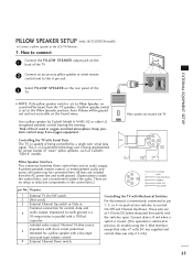
...and not accessible on the Sound menu. PILLOW NORMAL SPEAKER SPEAKER PILLOW SPEAKER SPEAKER SWITCH EXTERNAL EQUIPMENT SETUP I Connect a pillow speaker to previous LG models using the 5-Wire Interface except that only +7 volts DC was supplied and current draw was only 2.5 mA.) 25 Pillow speaker not ...A-16455-02 or other UL recognized pendant control bearing the warning: "Risk of the TV. 2 Connect an acccessory pillow speaker or wired remote control unit to control On/Off and Channel Up/Down. How to connect 1 Connect the PILLOW SPEAKER output jack on the rear panel of...
...and not accessible on the Sound menu. PILLOW NORMAL SPEAKER SPEAKER PILLOW SPEAKER SPEAKER SWITCH EXTERNAL EQUIPMENT SETUP I Connect a pillow speaker to previous LG models using the 5-Wire Interface except that only +7 volts DC was supplied and current draw was only 2.5 mA.) 25 Pillow speaker not ...A-16455-02 or other UL recognized pendant control bearing the warning: "Risk of the TV. 2 Connect an acccessory pillow speaker or wired remote control unit to control On/Off and Channel Up/Down. How to connect 1 Connect the PILLOW SPEAKER output jack on the rear panel of...

User Manual
Page 28
... on the TV using the INPUT button on the TV. 2. VGA (D-Sub 15 pin) Connection 1. How to the AUDIO IN (RGB/DVI) jack on the remote control. ( ) RGB OUTPUT AUDIO 1 UPDATE RESET USB IN RVUCE ONLY RS-232C IN (SERVICE ONLY) 2 ( NO) VIDEO RGB IN (PC) AUDIO AUDIO ...IN (RGB/DVI) REMOTE SPE CONTROL OUT ( ) ( ) S-VIDEO 26 EXTERNAL EQUIPMENT SETUP EXTERNAL EQUIPMENT SETUP PC SETUP This TV provides Plug and Play capability, meaning that the PC adjusts ...
... on the TV using the INPUT button on the TV. 2. VGA (D-Sub 15 pin) Connection 1. How to the AUDIO IN (RGB/DVI) jack on the remote control. ( ) RGB OUTPUT AUDIO 1 UPDATE RESET USB IN RVUCE ONLY RS-232C IN (SERVICE ONLY) 2 ( NO) VIDEO RGB IN (PC) AUDIO AUDIO ...IN (RGB/DVI) REMOTE SPE CONTROL OUT ( ) ( ) S-VIDEO 26 EXTERNAL EQUIPMENT SETUP EXTERNAL EQUIPMENT SETUP PC SETUP This TV provides Plug and Play capability, meaning that the PC adjusts ...

User Manual
Page 29
... audio output to another rate or adjust the brightness and contrast on the screen properly. 27 The fixed image could become permanently imprinted on the remote control. NOTES G To get the the best picture quality, adjust the PC graphics card to HDMI Connection 1. How to connect 1 Connect the DVI output of...
... audio output to another rate or adjust the brightness and contrast on the screen properly. 27 The fixed image could become permanently imprinted on the remote control. NOTES G To get the the best picture quality, adjust the PC graphics card to HDMI Connection 1. How to connect 1 Connect the DVI output of...

User Manual
Page 34
... DTV mode: Changes the audio language. RATIO Change the aspect ratio. WATCHING TV / CHANNEL CONTROL WATCHING TV / CHANNEL CONTROL REMOTE CONTROL FUNCTIONS (only 32LG3DC model) When using the remote control, aim it at the remote control sensor on -screen menus and adjust the system set- (Up/Down/Left Right/ENTER) tings to the last...
... DTV mode: Changes the audio language. RATIO Change the aspect ratio. WATCHING TV / CHANNEL CONTROL WATCHING TV / CHANNEL CONTROL REMOTE CONTROL FUNCTIONS (only 32LG3DC model) When using the remote control, aim it at the remote control sensor on -screen menus and adjust the system set- (Up/Down/Left Right/ENTER) tings to the last...
User Manual
Page 36
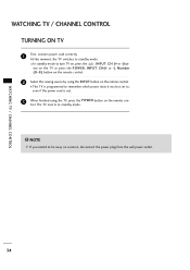
... the , INPUT, C H (+ or -)button on the TV or press the POWER, INPUT, C H(+ or -), Number ( 0~9 ) button on the remote control. 2 Select the viewing source by using the TV, press the POWER button on the remote control. At this moment, the TV switches to , even if the power cord is programmed to remember which... mode. WATCHING TV / CHANNEL CONTROL TURNING ON TV 1 First, connect power cord correctly. I This TV is out. 3 When finished using the INPUT button on the remote control. WATCHING TV / CHANNEL CONTROL 34
... the , INPUT, C H (+ or -)button on the TV or press the POWER, INPUT, C H(+ or -), Number ( 0~9 ) button on the remote control. 2 Select the viewing source by using the TV, press the POWER button on the remote control. At this moment, the TV switches to , even if the power cord is programmed to remember which... mode. WATCHING TV / CHANNEL CONTROL TURNING ON TV 1 First, connect power cord correctly. I This TV is out. 3 When finished using the INPUT button on the remote control. WATCHING TV / CHANNEL CONTROL 34

User Manual
Page 83
... the image is weak, reorient antenna to +, - Lines or streaks in pictures I Ensure that the correct remote operating mode is set ? No picture when connecting HDMI I Adjust Color in . The remote control doesn't work . I Check antenna (Change the direction of the picture. The problem may be with correct.../or location. I Try another product's power cord into wall power outlet? I Keep a sufficient distance between the product and the remote control causing obstruction. I Install new batteries. In this case use the latest cables that the batteries are pointing the...
... the image is weak, reorient antenna to +, - Lines or streaks in pictures I Ensure that the correct remote operating mode is set ? No picture when connecting HDMI I Adjust Color in . The remote control doesn't work . I Check antenna (Change the direction of the picture. The problem may be with correct.../or location. I Try another product's power cord into wall power outlet? I Keep a sufficient distance between the product and the remote control causing obstruction. I Install new batteries. In this case use the latest cables that the batteries are pointing the...

User Manual
Page 86
APPENDIX IR CODES 1. Remote Control IR Codes I Output waveform Single pulse, modulated with 37.917KHz signal at 455KHz Tc T1 I Configuration of frame 1st frame Carrier frequency FCAR = 1/TC = ... I Lead code APPENDIX 9 ms I Repeat code 4.5 ms 0.55 ms 9 ms 2.25 ms I Bit description Bit "0" 0.56 ms Bit "1" 0.56 ms 1.12 ms I Connect your wired remote control to Connect I Frame interval: Tf The waveform is transmitted as long as a key is depressed. 2.24 ms Tf Tf Tf=108ms @455KHz 84 How...
APPENDIX IR CODES 1. Remote Control IR Codes I Output waveform Single pulse, modulated with 37.917KHz signal at 455KHz Tc T1 I Configuration of frame 1st frame Carrier frequency FCAR = 1/TC = ... I Lead code APPENDIX 9 ms I Repeat code 4.5 ms 0.55 ms 9 ms 2.25 ms I Bit description Bit "0" 0.56 ms Bit "1" 0.56 ms 1.12 ms I Connect your wired remote control to Connect I Frame interval: Tf The waveform is transmitted as long as a key is depressed. 2.24 ms Tf Tf Tf=108ms @455KHz 84 How...

User Manual
Page 87
... Remote control Button 76 Number Key 0-9 Remote control Button 77 - (Dash) Remote control Button AF FLASHBK Remote control Button C4 VOL + Remote control Button C5 VOL - Remote control Button TIMER Remote control Button CC Remote control Button MUTE Remote control Button ADJUST Remote control Button MENU Remote control Button RETURN Remote control Button Remote control Button Remote control Button Remote control Button Remote control Button ENTER Remote...
... Remote control Button 76 Number Key 0-9 Remote control Button 77 - (Dash) Remote control Button AF FLASHBK Remote control Button C4 VOL + Remote control Button C5 VOL - Remote control Button TIMER Remote control Button CC Remote control Button MUTE Remote control Button ADJUST Remote control Button MENU Remote control Button RETURN Remote control Button Remote control Button Remote control Button Remote control Button Remote control Button ENTER Remote...


