
Owners Manual
Page 1
... on the back cover and quote this manual carefully before your dealer when you require service. As an ENERGY STAR Partner LGE U. S. LCD TV PLASMA TV OWNER'S MANUAL LCD TV MODELS 32LC7D 32LC7DC 37LC7D 42LC7D PLASMA TV MODELS 42PCSD 42PCSDC SOPCSD SOPCSDC Please read this information to your set. Retain it for energy efficiency. -.0 _J ENERGY STAR is a set...
... on the back cover and quote this manual carefully before your dealer when you require service. As an ENERGY STAR Partner LGE U. S. LCD TV PLASMA TV OWNER'S MANUAL LCD TV MODELS 32LC7D 32LC7DC 37LC7D 42LC7D PLASMA TV MODELS 42PCSD 42PCSDC SOPCSD SOPCSDC Please read this information to your set. Retain it for energy efficiency. -.0 _J ENERGY STAR is a set...

Owners Manual
Page 8
... exterior if there is stain or fingerprint on surface of that the following accessories are included with ferrite cores to maintain standard compliance for all models 2-Eye-bolts (Refer to p.16) 2-Wall brackets (Refer to p.16) D-sub 15 pin Cable Cable Management 7 This feature is missing, please contact the dealer where...
... exterior if there is stain or fingerprint on surface of that the following accessories are included with ferrite cores to maintain standard compliance for all models 2-Eye-bolts (Refer to p.16) 2-Wall brackets (Refer to p.16) D-sub 15 pin Cable Cable Management 7 This feature is missing, please contact the dealer where...
Owners Manual
Page 9
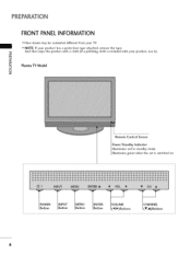
""_NOTE: If your product has a protection tape attached, remove the tape. -0 And then wipe the product with your TV. Illuminates green when the set is included with a cloth (If a polishing cloth is switched on. P__OWER _INPUT I Button I Button I Button _ENTER I Button "_VOLUME_ I (4l, l_)Buttons I (T,A)Buttons 8 PREPARATION FRONT PANELINFORMATION ,,,IHere shown may be somewhat different from your product, use it). _o r'rl _o Plasma TV Model i © z Remote Control Sensor Power/Standby Indicator Illuminates red in standby mode.
""_NOTE: If your product has a protection tape attached, remove the tape. -0 And then wipe the product with your TV. Illuminates green when the set is included with a cloth (If a polishing cloth is switched on. P__OWER _INPUT I Button I Button I Button _ENTER I Button "_VOLUME_ I (4l, l_)Buttons I (T,A)Buttons 8 PREPARATION FRONT PANELINFORMATION ,,,IHere shown may be somewhat different from your product, use it). _o r'rl _o Plasma TV Model i © z Remote Control Sensor Power/Standby Indicator Illuminates red in standby mode.

Owners Manual
Page 10
"0 m © z (A,V)Buttons (_I,I_) Buttons Button Button Button Button 9 LCD TV Model Remote Control Sensor Power/Standby Indicator llluminates red in standby mode. llluminates green when the set is switched on.
"0 m © z (A,V)Buttons (_I,I_) Buttons Button Button Button Button 9 LCD TV Model Remote Control Sensor Power/Standby Indicator llluminates red in standby mode. llluminates green when the set is switched on.
Owners Manual
Page 11
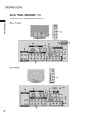
Plasma TV Model "0 _o m _o 0 z LCD TV Model 10 PREPARATION BACK PANELINFORMATION ,,,IHere shown may be somewhat different from your TV.
Plasma TV Model "0 _o m _o 0 z LCD TV Model 10 PREPARATION BACK PANELINFORMATION ,,,IHere shown may be somewhat different from your TV.

Owners Manual
Page 14
Plasma TV Model LCD TV Model 4 inches I 4 inches 4 inches 4 inches 4 inches I 4 inches 4 inches 4 inches 13 VESA WALL MOUNTING This product accepts a VESA-compliant mounting interface pad. (optional) There 4 threaded holes are available for attaching the bracket. =,_ Plasma TV Model LCD TV Model m 600 mm 600 mm (32LC7D/7DC only: 200 mm) O z 400 mm 400 mm (32LC7D/7DC only: 100 mm) DESKTOP PEDESTALINSTALLATION For proper ventilation, allow a clearance of 4 inches on all four sides from the wall.
Plasma TV Model LCD TV Model 4 inches I 4 inches 4 inches 4 inches 4 inches I 4 inches 4 inches 4 inches 13 VESA WALL MOUNTING This product accepts a VESA-compliant mounting interface pad. (optional) There 4 threaded holes are available for attaching the bracket. =,_ Plasma TV Model LCD TV Model m 600 mm 600 mm (32LC7D/7DC only: 200 mm) O z 400 mm 400 mm (32LC7D/7DC only: 100 mm) DESKTOP PEDESTALINSTALLATION For proper ventilation, allow a clearance of 4 inches on all four sides from the wall.
Owners Manual
Page 15
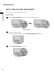
Install the CABLE MANAGEMENT as necessary. "0 Plasma TV Model r_ O Hold the CABLE MANAGEMENT with both hands and pull it backward as shown. © z CABLE MANAGEMENT e Connect the cables as shown. 14 PREPARATION BACK COVER FOR WIRE ARRANGEMENT ,,,IHere shown may be somewhat different from your TV. To connect an additional equipment, see the EXTERNAL EQUIPMENT SETUP section.
Install the CABLE MANAGEMENT as necessary. "0 Plasma TV Model r_ O Hold the CABLE MANAGEMENT with both hands and pull it backward as shown. © z CABLE MANAGEMENT e Connect the cables as shown. 14 PREPARATION BACK COVER FOR WIRE ARRANGEMENT ,,,IHere shown may be somewhat different from your TV. To connect an additional equipment, see the EXTERNAL EQUIPMENT SETUP section.

Owners Manual
Page 16
To connect an additional equipment, see the EXTERNAL EQUIPMENT SETUP section. © z O Install the CABLE MANAGEMENT as necessary. O Bundle the cables using the supplied TWISTER HOLDER. (This feature is not available for all models.) CABLE MANAGEMENT TWIST HOLDER 1S LCD TV Model -O _o m _o O onnect the cables as shown.
To connect an additional equipment, see the EXTERNAL EQUIPMENT SETUP section. © z O Install the CABLE MANAGEMENT as necessary. O Bundle the cables using the supplied TWISTER HOLDER. (This feature is not available for all models.) CABLE MANAGEMENT TWIST HOLDER 1S LCD TV Model -O _o m _o O onnect the cables as shown.

Owners Manual
Page 17
...on or hang from your product has the bolts in the eye-bolts position before inserting the eye-bolts, loosen the bolts. If your TV. _D r_ We recommend that children don't climb on the wall to the holes in the product. Caution: Please make sure that ..., _D potentially causing injury or damaging the product. PREPARATION ATTACHING THE TV TO A WALL ,,,IThis feature is not available for all models. ,,,iHere shown may be somewhat different from the TV. © z Plasma TV Model LCD TV Model Insert the eye-bolts (or TV brackets and bolts) to tighten the product to the wall as shown...
...on or hang from your product has the bolts in the eye-bolts position before inserting the eye-bolts, loosen the bolts. If your TV. _D r_ We recommend that children don't climb on the wall to the holes in the product. Caution: Please make sure that ..., _D potentially causing injury or damaging the product. PREPARATION ATTACHING THE TV TO A WALL ,,,IThis feature is not available for all models. ,,,iHere shown may be somewhat different from the TV. © z Plasma TV Model LCD TV Model Insert the eye-bolts (or TV brackets and bolts) to tighten the product to the wall as shown...

Owners Manual
Page 19
... receive Digital Over-the-air/Cable signals without an external digital set-top box. If connected to the owner's manual for LCD TV model. EXTERNAL EQUIPMENT SETUP 01T_o prevent the equipment damage, never plug in any power cords until you do receive digital signals from a digital set . operation) Select ...
... receive Digital Over-the-air/Cable signals without an external digital set-top box. If connected to the owner's manual for LCD TV model. EXTERNAL EQUIPMENT SETUP 01T_o prevent the equipment damage, never plug in any power cords until you do receive digital signals from a digital set . operation) Select ...

Owners Manual
Page 24
... sides of the VCR. VCR SETUP To avoid picture noise (interference), leave an adequate distance between the VCR and TV. How to use Set VCR output switch to 3 or 4 and then tune TV to the RF antenna in conse- How to connect O Connect the RF antenna out socket of time (Only Plasma... TV model). r_l x r_l When connecting with an antenna _o z r_l X_ c "0 r_l z L_ r_l c Wall Jack "0 Antenna 1. This phenomenon is used; Use the ISM feature in ...
... sides of the VCR. VCR SETUP To avoid picture noise (interference), leave an adequate distance between the VCR and TV. How to use Set VCR output switch to 3 or 4 and then tune TV to the RF antenna in conse- How to connect O Connect the RF antenna out socket of time (Only Plasma... TV model). r_l x r_l When connecting with an antenna _o z r_l X_ c "0 r_l z L_ r_l c Wall Jack "0 Antenna 1. This phenomenon is used; Use the ISM feature in ...

Owners Manual
Page 36
ON-SCREENMENUS SELECTION Your TV's OSD (On Screen Display) may differ slightly from what is shown in this manual. @ Press the MENU button and then use A or • button to select the each menu. @ Press the I_ button and then use A • _1 I_ button to display the available menus. SETUP PICTURE "1z < N -r" > Z Z fT1 N 0 It It Z LOCK For USA For Canada AUDIO _m 0 It OPTION It TIME Only Plasma TV model 35
ON-SCREENMENUS SELECTION Your TV's OSD (On Screen Display) may differ slightly from what is shown in this manual. @ Press the MENU button and then use A or • button to select the each menu. @ Press the I_ button and then use A • _1 I_ button to display the available menus. SETUP PICTURE "1z < N -r" > Z Z fT1 N 0 It It Z LOCK For USA For Canada AUDIO _m 0 It OPTION It TIME Only Plasma TV model 35

Owners Manual
Page 84
After that the remote may not control all models of other brands. If the device is successful. the currently selected device button is stored. If not, the remote should be programmed. The programming procedures ...
After that the remote may not control all models of other brands. If the device is successful. the currently selected device button is stored. If not, the remote should be programmed. The programming procedures ...

Owners Manual
Page 92
...][ ][NG][Data][x] 91 C8 q p ( _ p.94) [ q 0-1 l b 0~1 c (_p.95) I 0~1 m 0~1 -- Contrast k 09 s k 10, Color k 1_ Tint k 12. Color Temperature k d 0- 1 19. Red Adjustment k e 0~1 20. Green Adjustment k f 0 - 64 21. Plasma TV Model Only r 0- 64 s O~ 64 t 0 ~ 64 u 0~3 v 0 -
...][ ][NG][Data][x] 91 C8 q p ( _ p.94) [ q 0-1 l b 0~1 c (_p.95) I 0~1 m 0~1 -- Contrast k 09 s k 10, Color k 1_ Tint k 12. Color Temperature k d 0- 1 19. Red Adjustment k e 0~1 20. Green Adjustment k f 0 - 64 21. Plasma TV Model Only r 0- 64 s O~ 64 t 0 ~ 64 u 0~3 v 0 -

Owners Manual
Page 93
... ID][ ] [OK]NG] [Data] [x] 08. You can also adjust brightness in the Picture menu. Input Select (Command: x b) To select input source for the TV. Transmission[k] [e][] [Set ID] [ ] [Data] [Cr] .... See page 92;. Contrast (Command: k g) To adjust screen contrast. Brightness (Command: k h) To...In a like manner, if other functions transmit 'FF' data based on this format, Acknowledgement data feedback presents status about each function. * Note: In this model, TV will send the Acknowledge after power on remote control. Transmission[k] [c] [ ] [set ID] [ ] [Data] [Cr] Data Min: 0 _ Max...
... ID][ ] [OK]NG] [Data] [x] 08. You can also adjust brightness in the Picture menu. Input Select (Command: x b) To select input source for the TV. Transmission[k] [e][] [Set ID] [ ] [Data] [Cr] .... See page 92;. Contrast (Command: k g) To adjust screen contrast. Brightness (Command: k h) To...In a like manner, if other functions transmit 'FF' data based on this format, Acknowledgement data feedback presents status about each function. * Note: In this model, TV will send the Acknowledge after power on remote control. Transmission[k] [c] [ ] [set ID] [ ] [Data] [Cr] Data Min: 0 _ Max...

Owners Manual
Page 95
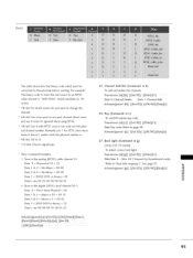
...: 0 - Acknowledgemen_ [$][ ][Set ID][ ][OK/NG] [Data] [x] 22. TransmgsiOn [j ][p][] [Set ID][] [Data] [cr] .... Low Power (Command: j q) (Only Plasma TV model) To control the low power function on ACknowledgemen_ [q][] [Set ID][] [OK/NG] [Data] [x] 24. Data3 & 4: Minor Channel Number Not needed for the Major and Minor, ... a) To tune channel to the Z E:I ] [ ] [Data2] [ ] [Data3] [ ] [Data4] [ ] [Data5] [cr] Digital channels have a Physical, Major, and Minor channel number. 21. ISM Method (Command: j p) (Only Plasma TV model) To avoid having a fixed image remain on screen.
...: 0 - Acknowledgemen_ [$][ ][Set ID][ ][OK/NG] [Data] [x] 22. TransmgsiOn [j ][p][] [Set ID][] [Data] [cr] .... Low Power (Command: j q) (Only Plasma TV model) To control the low power function on ACknowledgemen_ [q][] [Set ID][] [OK/NG] [Data] [x] 24. Data3 & 4: Minor Channel Number Not needed for the Major and Minor, ... a) To tune channel to the Z E:I ] [ ] [Data2] [ ] [Data3] [ ] [Data4] [ ] [Data5] [cr] Digital channels have a Physical, Major, and Minor channel number. 21. ISM Method (Command: j p) (Only Plasma TV model) To avoid having a fixed image remain on screen.
Owners Manual
Page 96
... 0: Channel Delete Data I: Channel Add Acknowledgemen_ [b][ ][Set ID][ ][OK/NG] [Data] ix] 26. Key (Command: m c) To send IR remote key code. Back Light (Command: m g) (Only LCD TV model) To adjust screen back light. * Tune Command Examples: Transmission [m] [g] [ ] [Set ID] [ ] [Data] [Cr] 1. Max: 64 (*transmit by Hexadecimal code) Data 0= Physical of 35 = 25 *Refer...
... 0: Channel Delete Data I: Channel Add Acknowledgemen_ [b][ ][Set ID][ ][OK/NG] [Data] ix] 26. Key (Command: m c) To send IR remote key code. Back Light (Command: m g) (Only LCD TV model) To adjust screen back light. * Tune Command Examples: Transmission [m] [g] [ ] [Set ID] [ ] [Data] [Cr] 1. Max: 64 (*transmit by Hexadecimal code) Data 0= Physical of 35 = 25 *Refer...


