
Owners Manual
Page 1
has determined that this product meets the ENERGY STAR guidelines for future reference. Retain it for energy efficiency. LCD TV PLASMA TV OWNER'S MANUAL LCD TV MODELS 32LC7D 32LC7DC 37LC7D 42LC7D PLASMA TV MODELS 42PCSD 42PCSDC SOPCSD SOPCSDC Please read this information to your set. Environmental Protection Agency(EPA). A.,Inc. operating Record model number and serial number of...
has determined that this product meets the ENERGY STAR guidelines for future reference. Retain it for energy efficiency. LCD TV PLASMA TV OWNER'S MANUAL LCD TV MODELS 32LC7D 32LC7DC 37LC7D 42LC7D PLASMA TV MODELS 42PCSD 42PCSDC SOPCSD SOPCSDC Please read this information to your set. Environmental Protection Agency(EPA). A.,Inc. operating Record model number and serial number of...

Owners Manual
Page 2
... 15 of the cable entry as practical. Connect the equipment to an outlet on , the user is connected. -Consult the dealer or an experienced radio/TV technician for proper grounding and, in accordance with the limits for compliance could void the user's authority to operate this equipment does cause harmful interference... interference in any way without written authorization from that the cable ground shall be determined by turning the equipment off and on a circuit different from LG Electronics.
... 15 of the cable entry as practical. Connect the equipment to an outlet on , the user is connected. -Consult the dealer or an experienced radio/TV technician for proper grounding and, in accordance with the limits for compliance could void the user's authority to operate this equipment does cause harmful interference... interference in any way without written authorization from that the cable ground shall be determined by turning the equipment off and on a circuit different from LG Electronics.

Owners Manual
Page 5
... Setup 18 DVD Setup 21 VCR Setup 23 Other A/V Source Setup 25 PC Setup 26 Audio Out Setup 31 Remote Control Functions 32 Turning On TV 34 Channel Selection 34 Volume Adjustment 34 On-Screen Menus Selection 35 Channel Setup - Add / Delete Channel (Manual Tuning) ......... (Sound Mode 56 Sound Setting Adjustment - Caption Option 66 Preset 45 - CONTENTS WARNING / CAUTION 1 SAFETY INSTRUCTIONS 2 FEATURE OF THIS TV 6 Accessories 7 Front Panel Information 8 Back Panel Information 10 Stand Installation 12 VESA Wall Mounting 13 Desktop Pedestal Installation 13 Back Cover for...
... Setup 18 DVD Setup 21 VCR Setup 23 Other A/V Source Setup 25 PC Setup 26 Audio Out Setup 31 Remote Control Functions 32 Turning On TV 34 Channel Selection 34 Volume Adjustment 34 On-Screen Menus Selection 35 Channel Setup - Add / Delete Channel (Manual Tuning) ......... (Sound Mode 56 Sound Setting Adjustment - Caption Option 66 Preset 45 - CONTENTS WARNING / CAUTION 1 SAFETY INSTRUCTIONS 2 FEATURE OF THIS TV 6 Accessories 7 Front Panel Information 8 Back Panel Information 10 Stand Installation 12 VESA Wall Mounting 13 Desktop Pedestal Installation 13 Back Cover for...
Owners Manual
Page 6
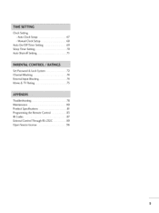
Manual Clock Setup 68 Auto On/Off Timer Setting 69 Sleep Timer Setting 70 Auto Shut-off Setting 71 Set Password & Lock System 72 Channel Blocking 74 External Input Blocking 74 Movie & TV Rating 75 Troubleshooting 78 Maintenance 80 Product Specifications 81 Programming the Remote Control 83 IR Codes 87 External Control Through RS-232C 89 Open Source License 96 S Auto Clock Setup 67 - Clock Setting -
Manual Clock Setup 68 Auto On/Off Timer Setting 69 Sleep Timer Setting 70 Auto Shut-off Setting 71 Set Password & Lock System 72 Channel Blocking 74 External Input Blocking 74 Movie & TV Rating 75 Troubleshooting 78 Maintenance 80 Product Specifications 81 Programming the Remote Control 83 IR Codes 87 External Control Through RS-232C 89 Open Source License 96 S Auto Clock Setup 67 - Clock Setting -

Owners Manual
Page 7
... dot defects may be visible on the screen. Doing so may be carried out in accordance to the HDMI (high-definition multimedia interface), LG TV with this product with one remote control. c. The fluorescent lamp used in this product must be a small "flicker" when it for ...of mercury. Disposal of this product contains a small amount of this logo works easily with TV. e"-_ _,[mPLInK television broadcast and playback system composed of SRS Labs, Inc. FOR LCD TV If the TV feels cold to the touch, there may produce some temporary distortion effects on the screen, ...
... dot defects may be visible on the screen. Doing so may be carried out in accordance to the HDMI (high-definition multimedia interface), LG TV with this product with one remote control. c. The fluorescent lamp used in this product must be a small "flicker" when it for ...of mercury. Disposal of this product contains a small amount of this logo works easily with TV. e"-_ _,[mPLInK television broadcast and playback system composed of SRS Labs, Inc. FOR LCD TV If the TV feels cold to the touch, there may produce some temporary distortion effects on the screen, ...
Owners Manual
Page 9
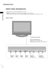
Illuminates green when the set is included with your product, use it). _o r'rl _o Plasma TV Model i © z Remote Control Sensor Power/Standby Indicator Illuminates red in standby mode. P__OWER _INPUT I Button I Button I Button _ENTER I Button "_VOLUME_ I (4l, l_)Buttons I (T,A)Buttons 8 PREPARATION FRONT PANELINFORMATION ,,,IHere shown may be somewhat different from your product has a protection tape attached, remove the tape. -0 And then wipe the product with a cloth (If a polishing cloth is switched on. ""_NOTE: If your TV.
Illuminates green when the set is included with your product, use it). _o r'rl _o Plasma TV Model i © z Remote Control Sensor Power/Standby Indicator Illuminates red in standby mode. P__OWER _INPUT I Button I Button I Button _ENTER I Button "_VOLUME_ I (4l, l_)Buttons I (T,A)Buttons 8 PREPARATION FRONT PANELINFORMATION ,,,IHere shown may be somewhat different from your product has a protection tape attached, remove the tape. -0 And then wipe the product with a cloth (If a polishing cloth is switched on. ""_NOTE: If your TV.

Owners Manual
Page 10
"0 m © z (A,V)Buttons (_I,I_) Buttons Button Button Button Button 9 llluminates green when the set is switched on. LCD TV Model Remote Control Sensor Power/Standby Indicator llluminates red in standby mode.
"0 m © z (A,V)Buttons (_I,I_) Buttons Button Button Button Button 9 llluminates green when the set is switched on. LCD TV Model Remote Control Sensor Power/Standby Indicator llluminates red in standby mode.
Owners Manual
Page 11
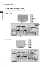
PREPARATION BACK PANELINFORMATION ,,,IHere shown may be somewhat different from your TV. Plasma TV Model "0 _o m _o 0 z LCD TV Model 10
PREPARATION BACK PANELINFORMATION ,,,IHere shown may be somewhat different from your TV. Plasma TV Model "0 _o m _o 0 z LCD TV Model 10

Owners Manual
Page 12
... or DTV. @ SERVICE O Remote Control Port Connect a wired remote control. -O _o m _o © z @ HDMI/DVI IN 1, HDMI IN 2 Connect a HDMI (DVI) connection to operate the TV on DC power. 11
... or DTV. @ SERVICE O Remote Control Port Connect a wired remote control. -O _o m _o © z @ HDMI/DVI IN 1, HDMI IN 2 Connect a HDMI (DVI) connection to operate the TV on DC power. 11
Owners Manual
Page 13
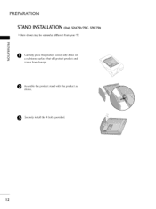
m i O Carefully place the product screen side down on 0 z a cushioned surface that will protect product and screen from your TV. e ssemble the product stand with the product as shown. 0 Securely install the 4 bolts provided. 12 PREPARATION STAND INSTALLATION (Onl3y2LC7D/7DC, 37LC7D) Here shown may be somewhat different from damage.
m i O Carefully place the product screen side down on 0 z a cushioned surface that will protect product and screen from your TV. e ssemble the product stand with the product as shown. 0 Securely install the 4 bolts provided. 12 PREPARATION STAND INSTALLATION (Onl3y2LC7D/7DC, 37LC7D) Here shown may be somewhat different from damage.

Owners Manual
Page 14
Plasma TV Model LCD TV Model 4 inches I 4 inches 4 inches 4 inches 4 inches I 4 inches 4 inches 4 inches 13 VESA WALL MOUNTING This product accepts a VESA-compliant mounting interface pad. (optional) There 4 threaded holes are available for attaching the bracket. =,_ Plasma TV Model LCD TV Model m 600 mm 600 mm (32LC7D/7DC only: 200 mm) O z 400 mm 400 mm (32LC7D/7DC only: 100 mm) DESKTOP PEDESTALINSTALLATION For proper ventilation, allow a clearance of 4 inches on all four sides from the wall.
Plasma TV Model LCD TV Model 4 inches I 4 inches 4 inches 4 inches 4 inches I 4 inches 4 inches 4 inches 13 VESA WALL MOUNTING This product accepts a VESA-compliant mounting interface pad. (optional) There 4 threaded holes are available for attaching the bracket. =,_ Plasma TV Model LCD TV Model m 600 mm 600 mm (32LC7D/7DC only: 200 mm) O z 400 mm 400 mm (32LC7D/7DC only: 100 mm) DESKTOP PEDESTALINSTALLATION For proper ventilation, allow a clearance of 4 inches on all four sides from the wall.
Owners Manual
Page 15
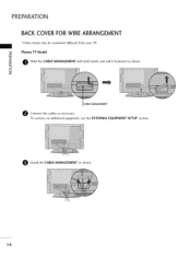
To connect an additional equipment, see the EXTERNAL EQUIPMENT SETUP section. Install the CABLE MANAGEMENT as necessary. PREPARATION BACK COVER FOR WIRE ARRANGEMENT ,,,IHere shown may be somewhat different from your TV. "0 Plasma TV Model r_ O Hold the CABLE MANAGEMENT with both hands and pull it backward as shown. © z CABLE MANAGEMENT e Connect the cables as shown. 14
To connect an additional equipment, see the EXTERNAL EQUIPMENT SETUP section. Install the CABLE MANAGEMENT as necessary. PREPARATION BACK COVER FOR WIRE ARRANGEMENT ,,,IHere shown may be somewhat different from your TV. "0 Plasma TV Model r_ O Hold the CABLE MANAGEMENT with both hands and pull it backward as shown. © z CABLE MANAGEMENT e Connect the cables as shown. 14

Owners Manual
Page 16
O Bundle the cables using the supplied TWISTER HOLDER. (This feature is not available for all models.) CABLE MANAGEMENT TWIST HOLDER 1S To connect an additional equipment, see the EXTERNAL EQUIPMENT SETUP section. © z O Install the CABLE MANAGEMENT as necessary. LCD TV Model -O _o m _o O onnect the cables as shown.
O Bundle the cables using the supplied TWISTER HOLDER. (This feature is not available for all models.) CABLE MANAGEMENT TWIST HOLDER 1S To connect an additional equipment, see the EXTERNAL EQUIPMENT SETUP section. © z O Install the CABLE MANAGEMENT as necessary. LCD TV Model -O _o m _o O onnect the cables as shown.

Owners Manual
Page 17
...to the wall as shown in the picture. Caution: Please make sure that the TV be attached to a wall so it cannot be somewhat different from the TV. © z Plasma TV Model LCD TV Model Insert the eye-bolts (or TV brackets and bolts) to tighten the product to the holes in the product. ...eye-bolts or brackets are tightened securely. 01U_se a sturdy rope (not provided as parts of the bracket that you set up the TV close to the wall. PREPARATION ATTACHING THE TV TO A WALL ,,,IThis feature is not available for all models. ,,,iHere shown may be pulled in a forward direction, _D ...
...to the wall as shown in the picture. Caution: Please make sure that the TV be attached to a wall so it cannot be somewhat different from the TV. © z Plasma TV Model LCD TV Model Insert the eye-bolts (or TV brackets and bolts) to tighten the product to the holes in the product. ...eye-bolts or brackets are tightened securely. 01U_se a sturdy rope (not provided as parts of the bracket that you set up the TV close to the wall. PREPARATION ATTACHING THE TV TO A WALL ,,,IThis feature is not available for all models. ,,,iHere shown may be pulled in a forward direction, _D ...
Owners Manual
Page 18
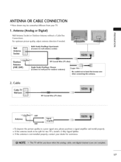
...) Outdo Antenn (VHF, UHF) RF Coaxial Wire (75 ohm) __/-- /I S(Cinognlnee-cfat miltyo wDawllejlalicnkgsf/oHrouosuetsdoor antenna) _ot_-_] t o bend ..t.h..e.....b..r.o...n..z..e....w...i.r.e. Cable Cable TV Wall Jack Antenna _ UHF VHF To improve the picture quality in a poor signal area, please purchase a signal amplifier and install properly. 01_If the antenna needs...be somewhat different from your dealer for assistance. 17 ANTENNA OR CABLE CONNECTION ""_Here shown may be split for two TV's, install a 2-Way Signal Splitter. 01_If the antenna is not installed properly, contact your...
...) Outdo Antenn (VHF, UHF) RF Coaxial Wire (75 ohm) __/-- /I S(Cinognlnee-cfat miltyo wDawllejlalicnkgsf/oHrouosuetsdoor antenna) _ot_-_] t o bend ..t.h..e.....b..r.o...n..z..e....w...i.r.e. Cable Cable TV Wall Jack Antenna _ UHF VHF To improve the picture quality in a poor signal area, please purchase a signal amplifier and install properly. 01_If the antenna needs...be somewhat different from your dealer for assistance. 17 ANTENNA OR CABLE CONNECTION ""_Here shown may be split for two TV's, install a 2-Way Signal Splitter. 01_If the antenna is not installed properly, contact your...

Owners Manual
Page 19
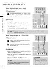
...part of EXTERNAL EQUIPMENT SETUP mainly use -O Turn on r_3 X:) the set. When connecting Component cable r_3 x I. How to the owner's manual for LCD TV model. However, if you have finished connecting all equipment. How to connect r_3 _o z O Connect the video outputs (Y, PB, PR) of the digital... top box to the figure as shown below. If connected to the COMPONENT IN AUDIO 1 jacks on the remote control. HD RECEIVERSETUP This TV can receive Digital Over-the-air/Cable signals without an external digital set-top box. operation) Select Component 1 input source by using the ...
...part of EXTERNAL EQUIPMENT SETUP mainly use -O Turn on r_3 X:) the set. When connecting Component cable r_3 x I. How to the owner's manual for LCD TV model. However, if you have finished connecting all equipment. How to connect r_3 _o z O Connect the video outputs (Y, PB, PR) of the digital... top box to the figure as shown below. If connected to the COMPONENT IN AUDIO 1 jacks on the remote control. HD RECEIVERSETUP This TV can receive Digital Over-the-air/Cable signals without an external digital set-top box. operation) Select Component 1 input source by using the ...

Owners Manual
Page 22
... use m c 01_Turn on the DVD player, insert a DVD. 01_Select Component 1 input source by using the INPUT button on DVD player 21 Component ports on the TV Video output ports on the remote control. 01_If connected to the x COMPONENT IN VIDE01 jacks on the set . m XD c O Connect the audio outputs of the...
... use m c 01_Turn on the DVD player, insert a DVD. 01_Select Component 1 input source by using the INPUT button on DVD player 21 Component ports on the TV Video output ports on the remote control. 01_If connected to the x COMPONENT IN VIDE01 jacks on the set . m XD c O Connect the audio outputs of the...

Owners Manual
Page 24
... connecting with an antenna _o z r_l X_ c "0 r_l z L_ r_l c Wall Jack "0 Antenna 1. How to use Set VCR output switch to 3 or 4 and then tune TV to all manufactures and in conse- the fixed images on the screen. How to the VCR owner's manual.) 23 quence the manufactures warranty does not... a video tape into the VCR and press PLAY on the set. 2. od of the screen may remain visible on the sides of time (Only Plasma TV model). IN socket on the VCR. (Refer to connect O Connect the RF antenna out socket of the VCR. VCR SETUP To avoid picture noise (interference...
... connecting with an antenna _o z r_l X_ c "0 r_l z L_ r_l c Wall Jack "0 Antenna 1. How to use Set VCR output switch to 3 or 4 and then tune TV to all manufactures and in conse- the fixed images on the screen. How to the VCR owner's manual.) 23 quence the manufactures warranty does not... a video tape into the VCR and press PLAY on the set. 2. od of the screen may remain visible on the sides of time (Only Plasma TV model). IN socket on the VCR. (Refer to connect O Connect the RF antenna out socket of the VCR. VCR SETUP To avoid picture noise (interference...
Owners Manual
Page 25
... control. 01_If connected to AV IN2, select AV2 input source. Connect the audio outputs of the VCR to connect O Connect the AUDIO/VIDEO jacks between TV and VCR.
... control. 01_If connected to AV IN2, select AV2 input source. Connect the audio outputs of the VCR to connect O Connect the AUDIO/VIDEO jacks between TV and VCR.

Owners Manual
Page 26
How to AV IN I input, select AV I input source. 01_Operate the corresponding external equipment. Camcorder Video Game Set r_ x r_ _o z r_ X:) c r_ z r_ c -O 25 Match the jack colors. (Video = yellow, Audio Left = white, and Audio Right = red) 2. OTHERA/V SOURCESETUP 1. How to use 01_Select AV2 input source by using the INPUT button on the remote control. 01_If connected to connect 0 Connect the AUDIO/VIDEO jacks between TV and external equipment.
How to AV IN I input, select AV I input source. 01_Operate the corresponding external equipment. Camcorder Video Game Set r_ x r_ _o z r_ X:) c r_ z r_ c -O 25 Match the jack colors. (Video = yellow, Audio Left = white, and Audio Right = red) 2. OTHERA/V SOURCESETUP 1. How to use 01_Select AV2 input source by using the INPUT button on the remote control. 01_If connected to connect 0 Connect the AUDIO/VIDEO jacks between TV and external equipment.


