Owner's Manual (English)
Page 4
..., if not installed and used in any way without written authorization from that interference will not occur in the literature accompanying the appliance. Any changes or modifications not expressly approved by turning the equipment off and on a circuit different from LG Electronics. Connect the equipment to Article 820-40 of important operating and maintenance (servicing) instructions in a particular installation. MFL34797033...
..., if not installed and used in any way without written authorization from that interference will not occur in the literature accompanying the appliance. Any changes or modifications not expressly approved by turning the equipment off and on a circuit different from LG Electronics. Connect the equipment to Article 820-40 of important operating and maintenance (servicing) instructions in a particular installation. MFL34797033...
Owner's Manual (English)
Page 5
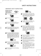
... periods of time. 4 Do not install near water. 8 Use only with the apparatus. Do not connect too many appliances to the same AC power outlet as this owner's manual to be placed upon a dedicated circuit; Servicing is used, use this apparatus or antenna during lighting storms or when unused for replacement of the polarized or grounding-type plug. Check the specification page of the TV. 13 Do...
... periods of time. 4 Do not install near water. 8 Use only with the apparatus. Do not connect too many appliances to the same AC power outlet as this owner's manual to be placed upon a dedicated circuit; Servicing is used, use this apparatus or antenna during lighting storms or when unused for replacement of the polarized or grounding-type plug. Check the specification page of the TV. 13 Do...
Owner's Manual (English)
Page 6
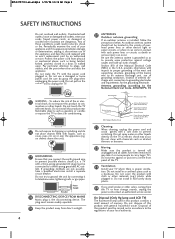
... not expose to plugs, wall outlets, and the point where the cord exits the appliance. on or over - The plug must be connected to the regulations of antenna dis- On Disposal (Only Hg lamp used LCD TV) The fluorescent lamp used in a door, or walked upon. Protect the power cord from direct sunlight. 4 20 ANTENNAS Outdoor antenna grounding If an outdoor antenna is installed, follow the...
... not expose to plugs, wall outlets, and the point where the cord exits the appliance. on or over - The plug must be connected to the regulations of antenna dis- On Disposal (Only Hg lamp used LCD TV) The fluorescent lamp used in a door, or walked upon. Protect the power cord from direct sunlight. 4 20 ANTENNAS Outdoor antenna grounding If an outdoor antenna is installed, follow the...
Owner's Manual (English)
Page 7
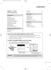
... want to a wall 14 Desktop Pedestal Installation 14 Stand Installation 15 VESA Wall Mounting 15 Antenna or Cable Connection 16 EXTERNAL EQUIPMENT SETUP HD Receiver Setup 17 DVD Setup 18 VCR Setup 19 PC Setup 20 WATCHING TV Turning On TV 21 Channel Selection 21 Volume Adjustment 21 Channel Search 22 On-Screen Menus Selection 23 APPENDIX Troubleshooting 26 Maintenance 28 Product Specifications 29 Open Source Software Notice 30 HOW TO USE THE OWNER'S MANUAL ON THE CD-ROM To view the Owner's Manual on the...
... want to a wall 14 Desktop Pedestal Installation 14 Stand Installation 15 VESA Wall Mounting 15 Antenna or Cable Connection 16 EXTERNAL EQUIPMENT SETUP HD Receiver Setup 17 DVD Setup 18 VCR Setup 19 PC Setup 20 WATCHING TV Turning On TV 21 Channel Selection 21 Volume Adjustment 21 Channel Search 22 On-Screen Menus Selection 23 APPENDIX Troubleshooting 26 Maintenance 28 Product Specifications 29 Open Source Software Notice 30 HOW TO USE THE OWNER'S MANUAL ON THE CD-ROM To view the Owner's Manual on the...
Owner's Manual (English)
Page 8
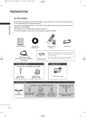
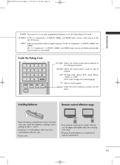
... all models 32LC7D/7DC, 37LC7D, 32LG10 only Cable Management 2- TV Bracket Bolts 2- TV Brackets, Twist Holder (Refer to p.14) 2- CD Manual (Refer to p.5) 1 4 7 Remote Control, Batteries Power Cord 75ohm Round Cable (This feature is stain or fingerprint on the exterior only with (Refer to p.14) the twist holder. 4-Bolts for all models Option Extras 2-Eye-bolts (Refer to p.14) 2-Wall brackets (Refer to p.14) D-sub 15 pin Cable For LCD TV models This...
... all models 32LC7D/7DC, 37LC7D, 32LG10 only Cable Management 2- TV Bracket Bolts 2- TV Brackets, Twist Holder (Refer to p.14) 2- CD Manual (Refer to p.5) 1 4 7 Remote Control, Batteries Power Cord 75ohm Round Cable (This feature is stain or fingerprint on the exterior only with (Refer to p.14) the twist holder. 4-Bolts for all models Option Extras 2-Eye-bolts (Refer to p.14) 2-Wall brackets (Refer to p.14) D-sub 15 pin Cable For LCD TV models This...
Owner's Manual (English)
Page 9
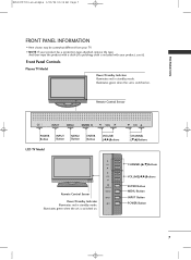
...Illuminates green when the set is switched on . ENTER MENU INPUT CHANNEL (E,D)Buttons CHANNEL(D,E)Buttons VOLUME(F,G)Buttons ENTER Button MENU Button INPUT Button POWER Button 7 Illuminates green when the set is switched on . Remote Control Sensor INPUT INPUT MENU ENTER MVOELNU ECHNTER VOL CH POWER Button INPUT Button MENU Button ENTER Button VOLUME (F,G)Buttons LCD TV Model CH CH VOL ENTER MENU VOL INPUT Remote Control Sensor Power/Standby Indicator Illuminates red in standby mode. MFL34797033-en-simple 1/20/04 12:34 AM Page 7 PREPARATION FRONT PANEL INFORMATION...
...Illuminates green when the set is switched on . ENTER MENU INPUT CHANNEL (E,D)Buttons CHANNEL(D,E)Buttons VOLUME(F,G)Buttons ENTER Button MENU Button INPUT Button POWER Button 7 Illuminates green when the set is switched on . Remote Control Sensor INPUT INPUT MENU ENTER MVOELNU ECHNTER VOL CH POWER Button INPUT Button MENU Button ENTER Button VOLUME (F,G)Buttons LCD TV Model CH CH VOL ENTER MENU VOL INPUT Remote Control Sensor Power/Standby Indicator Illuminates red in standby mode. MFL34797033-en-simple 1/20/04 12:34 AM Page 7 PREPARATION FRONT PANEL INFORMATION...
Owner's Manual (English)
Page 11
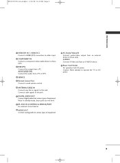
Connect cable signals to this jack. 7 DIGITAL AUDIO OUT Connect digital audio from various types of equipment. 10 AV (Audio/Video) IN Connect audio/video output from a PC or DTV. 4 SERVICE 5 Remote Control Port Connect a wired remote control. 6 ANTENNA/CABLE IN Connect over-the air signals to this jack. S-VIDEO Connect S-Video out from a PC. Note: In standby mode, these ports do not work. 8 RS-232C IN (CONTROL & SERVICE) PORT For external control devices. 9 AUDIO OUT Connect analog audio to various types of equipment. Caution: Never attempt to these jacks. MFL34797033-en-simple ...
Connect cable signals to this jack. 7 DIGITAL AUDIO OUT Connect digital audio from various types of equipment. 10 AV (Audio/Video) IN Connect audio/video output from a PC or DTV. 4 SERVICE 5 Remote Control Port Connect a wired remote control. 6 ANTENNA/CABLE IN Connect over-the air signals to this jack. S-VIDEO Connect S-Video out from a PC. Note: In standby mode, these ports do not work. 8 RS-232C IN (CONTROL & SERVICE) PORT For external control devices. 9 AUDIO OUT Connect analog audio to various types of equipment. Caution: Never attempt to these jacks. MFL34797033-en-simple ...
Owner's Manual (English)
Page 12
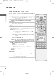
... program channels such as 2-1, 2-2, etc. TV INPUT TV AUDIO POWER DVD MODE CABLE INPUT VCR STB BRIGHT - MENU BRIGHT + ENTER EXIT TIMER RATIO SIMPLINK VOL MUTE FAV CH 1 2 3 4 5 6 7 8 9 0 BACK 10 When you toggle this button, the SimpLink menu appears at the remote control sensor on screen. FAV Scroll through the programmed Favorite channels. UP/DOWN NUMBER button - (DASH) Used to the last channel viewed. TIMER Select the amount of AV devices connected to TV viewing from any menu. CHANNEL Select available channels. control buttons MENU Displays...
... program channels such as 2-1, 2-2, etc. TV INPUT TV AUDIO POWER DVD MODE CABLE INPUT VCR STB BRIGHT - MENU BRIGHT + ENTER EXIT TIMER RATIO SIMPLINK VOL MUTE FAV CH 1 2 3 4 5 6 7 8 9 0 BACK 10 When you toggle this button, the SimpLink menu appears at the remote control sensor on screen. FAV Scroll through the programmed Favorite channels. UP/DOWN NUMBER button - (DASH) Used to the last channel viewed. TIMER Select the amount of AV devices connected to TV viewing from any menu. CHANNEL Select available channels. control buttons MENU Displays...
Owner's Manual (English)
Page 13
... the factory preset picture depend on the back side and install the batteries matching correct polarity (+ with +, - MENU BRIGHT + TV INPUT TV AUDIO POWER DVD MODE CABLE INPUT VCR STB BRIGHT - MFL34797033-en-simple 1/20/04 12:34 AM Page 11 PREPARATION POWER Turns your TV or any other programmed equipment on or off, depending on the mode. ADJUST Adjust the screen resolution, position, size and phase. I Use a remote control up to the last TV channel. CC Select a closed caption...
... the factory preset picture depend on the back side and install the batteries matching correct polarity (+ with +, - MENU BRIGHT + TV INPUT TV AUDIO POWER DVD MODE CABLE INPUT VCR STB BRIGHT - MFL34797033-en-simple 1/20/04 12:34 AM Page 11 PREPARATION POWER Turns your TV or any other programmed equipment on or off, depending on the mode. ADJUST Adjust the screen resolution, position, size and phase. I Use a remote control up to the last TV channel. CC Select a closed caption...
Owner's Manual (English)
Page 15
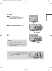
... How to remove the CABLE MANAGEMENT G Hold the CABLE MANAGEMENT with both hands and pull it backward. 13 MFL34797033-en-simple 1/20/04 12:34 AM Page 13 PREPARATION LCD TV Model 1 Connect the cables as shown. 3 Bundle the cables using the supplied TWISTER HOLDER.... (This feature is dropped, you may be injured or the product may be broken. If the product is not available for all models.) ! To connect an additional equipment, see the EXTERNAL EQUIPMENT SETUP section. 2 Install the CABLE...
... How to remove the CABLE MANAGEMENT G Hold the CABLE MANAGEMENT with both hands and pull it backward. 13 MFL34797033-en-simple 1/20/04 12:34 AM Page 13 PREPARATION LCD TV Model 1 Connect the cables as shown. 3 Bundle the cables using the supplied TWISTER HOLDER.... (This feature is dropped, you may be injured or the product may be broken. If the product is not available for all models.) ! To connect an additional equipment, see the EXTERNAL EQUIPMENT SETUP section. 2 Install the CABLE...
Owner's Manual (English)
Page 17
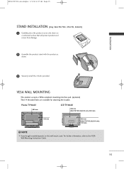
... the VESA Wall Mounting Instruction Guide. ( ) ( ) 15 NOTE G Screw length needed depends on a cushioned surface that will protect product and screen from damage. 2 Assemble the product stand with the product as shown. 3 Securely install the 4 bolts provided. VESA WALL MOUNTING This product accepts a VESA-compliant mounting interface pad. (optional) There 4 threaded holes are available for attaching the bracket. MFL34797033-en-simple 1/1/04 6:57 AM Page 15 PREPARATION STAND INSTALLATION (Only 32LC7D...
... the VESA Wall Mounting Instruction Guide. ( ) ( ) 15 NOTE G Screw length needed depends on a cushioned surface that will protect product and screen from damage. 2 Assemble the product stand with the product as shown. 3 Securely install the 4 bolts provided. VESA WALL MOUNTING This product accepts a VESA-compliant mounting interface pad. (optional) There 4 threaded holes are available for attaching the bracket. MFL34797033-en-simple 1/1/04 6:57 AM Page 15 PREPARATION STAND INSTALLATION (Only 32LC7D...
Owner's Manual (English)
Page 19
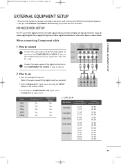
...-air/Cable signals without an external digital set -top box. I Turn on the digital set-top box. (Refer to use picture for the digital set -top box. Match the jack colors (Y = green, PB = blue, and 1 PR = red). /DVI IN VIDEO AUDIO S- ( ) Connect the audio output of EXTERNAL EQUIPMENT SETUP mainly use I If connected to 2 the COMPONENT IN AUDIO 1 jacks on the set. EXTERNAL EQUIPMENT SETUP 2. MFL34797033-en-simple 1/20/04 12:34 AM Page 17 EXTERNAL EQUIPMENT SETUP I Select Component 1 input source by using the INPUT button on the remote control. operation) I To...
...-air/Cable signals without an external digital set -top box. I Turn on the digital set-top box. (Refer to use picture for the digital set -top box. Match the jack colors (Y = green, PB = blue, and 1 PR = red). /DVI IN VIDEO AUDIO S- ( ) Connect the audio output of EXTERNAL EQUIPMENT SETUP mainly use I If connected to 2 the COMPONENT IN AUDIO 1 jacks on the set. EXTERNAL EQUIPMENT SETUP 2. MFL34797033-en-simple 1/20/04 12:34 AM Page 17 EXTERNAL EQUIPMENT SETUP I Select Component 1 input source by using the INPUT button on the remote control. operation) I To...
Owner's Manual (English)
Page 20
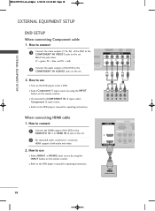
...colors COMPONENT IN R (CONT 2 (Y = green, PB = blue, and PR = red). 1 Connect the audio outputs of the DVD to the 2 COMPONENT IN AUDIO1 jacks on the DVD player, insert a DVD. HDMI support(s b) oth audio and video. 2. I Turn on the set. How to the DVD player's manual for operating instructions. 1 2 Y PB PR L R When connecting HDMI cable 1. How to use I Refer to use I Select Component 1 input source by using the INPUT button on the set . I VIDEO 1 HDMI-DVD OUTPUT 18 How to connect 1 Connect the video outputs (Y, PB, PR) of the DVD to the DVD...
...colors COMPONENT IN R (CONT 2 (Y = green, PB = blue, and PR = red). 1 Connect the audio outputs of the DVD to the 2 COMPONENT IN AUDIO1 jacks on the DVD player, insert a DVD. HDMI support(s b) oth audio and video. 2. I Turn on the set. How to the DVD player's manual for operating instructions. 1 2 Y PB PR L R When connecting HDMI cable 1. How to use I Refer to use I Select Component 1 input source by using the INPUT button on the set . I VIDEO 1 HDMI-DVD OUTPUT 18 How to connect 1 Connect the video outputs (Y, PB, PR) of the DVD to the DVD...
Owner's Manual (English)
Page 21
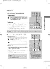
... VCR to the VCR owner's manual.) I Select A V 1 input source by using the INPUT button on the set . MFL34797033-en-simple 1/20/04 12:34 AM Page 19 EXTERNAL EQUIPMENT SETUP ( ) VCR SETUP When connecting with an S-Video cable 1. When connecting with a RCA cable 1. ANT IN S-VIDEO VIDEO L R ANT OUT OUTPUT SWITCH 2 Connect the audio outputs of the set . NOTE G The picture quality is improved: compared to the S -VIDEO input on the remote control. How to use I Insert a video tape into the...
... VCR to the VCR owner's manual.) I Select A V 1 input source by using the INPUT button on the set . MFL34797033-en-simple 1/20/04 12:34 AM Page 19 EXTERNAL EQUIPMENT SETUP ( ) VCR SETUP When connecting with an S-Video cable 1. When connecting with a RCA cable 1. ANT IN S-VIDEO VIDEO L R ANT OUT OUTPUT SWITCH 2 Connect the audio outputs of the set . NOTE G The picture quality is improved: compared to the S -VIDEO input on the remote control. How to use I Insert a video tape into the...
Owner's Manual (English)
Page 22
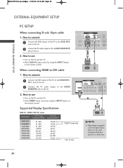
...AUDIO S-VIDEO VI ( ) 1 ( ) 2 When connecting HDMI to use I Select RGB-PC input source by using the INPUT button on the remote control. I Turn on the PC and the TV. How to find best picture in a little time. 20 I Turn on the PC and the TV. RGB OUTPUT AUDIO HDMI IN ANTENNA/ CABLE IN RGB IN DIGITAL RGB(PC) AUDIO REMOTE AUDIO OUT (RGB/DVI) SERVICE CONTROL IN OPTICAL 2 2 1 1 HDMI/DVI IN COMPONENT IN RS-232C IN (CONTROL & SERVICE) AUDIO VIDEO AUDIO S-VIDEO VIDEO (MONO) A ( ) 1 2 Supported Display Specifications RGB-PC, HDMI1/DVI-PC mode Resolution...
...AUDIO S-VIDEO VI ( ) 1 ( ) 2 When connecting HDMI to use I Select RGB-PC input source by using the INPUT button on the remote control. I Turn on the PC and the TV. How to find best picture in a little time. 20 I Turn on the PC and the TV. RGB OUTPUT AUDIO HDMI IN ANTENNA/ CABLE IN RGB IN DIGITAL RGB(PC) AUDIO REMOTE AUDIO OUT (RGB/DVI) SERVICE CONTROL IN OPTICAL 2 2 1 1 HDMI/DVI IN COMPONENT IN RS-232C IN (CONTROL & SERVICE) AUDIO VIDEO AUDIO S-VIDEO VIDEO (MONO) A ( ) 1 2 Supported Display Specifications RGB-PC, HDMI1/DVI-PC mode Resolution...
Owner's Manual (English)
Page 24
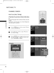
... Auto Tuning Manual Tuning Channel Edit 2 Processing Auto Tuning... Run Auto Tuning again after any Antenna/Cable connection changes. A password is required to gain access to Auto Tuning menu if the Lock System is turned on the channel list. NOTE Analog TV antenna Digital DTV antenna Analog CATV cable Digital CADTV cable TV INPUT POWER TV AUDIO DVD MODE CABLE INPUT VCR STB BRIGHT - Press to complete the channel search cycle for ANTENNA and CABLE. ! MFL34797033-en-simple 1/20/04 12:34 AM Page 22 WATCHING TV WATCHING TV CHANNEL SEARCH Auto Scan (Auto...
... Auto Tuning Manual Tuning Channel Edit 2 Processing Auto Tuning... Run Auto Tuning again after any Antenna/Cable connection changes. A password is required to gain access to Auto Tuning menu if the Lock System is turned on the channel list. NOTE Analog TV antenna Digital DTV antenna Analog CATV cable Digital CADTV cable TV INPUT POWER TV AUDIO DVD MODE CABLE INPUT VCR STB BRIGHT - Press to complete the channel search cycle for ANTENNA and CABLE. ! MFL34797033-en-simple 1/20/04 12:34 AM Page 22 WATCHING TV WATCHING TV CHANNEL SEARCH Auto Scan (Auto...
Owner's Manual (English)
Page 25
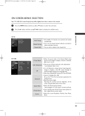
... the screen using the black level of three automatic color adjustments : Cool, Medium, Warm, User I Adjust the screen Resolution, Position, Size, Phase, Reset. 23 I Cinema 3:2 Mode (On, Off) Set up the TV for the best picture appearance for viewing movies. Color Temperature I Choose one of the screen. Screen I It is shown in this manual. 1 Press the MENU button and then use D or E button to select the each menu. 2 Press the G button and then use D E F G button to display a real HD source through...
... the screen using the black level of three automatic color adjustments : Cool, Medium, Warm, User I Adjust the screen Resolution, Position, Size, Phase, Reset. 23 I Cinema 3:2 Mode (On, Off) Set up the TV for the best picture appearance for viewing movies. Color Temperature I Choose one of the screen. Screen I It is shown in this manual. 1 Press the MENU button and then use D or E button to select the each menu. 2 Press the G button and then use D E F G button to display a real HD source through...
Owner's Manual (English)
Page 27
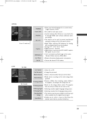
... screen menus : English, Spanish, French. Input Block I Use it to minimize any fixed image on your family do not want to block. I Enables you wish to view. I Change the password. Set Password I Reduces the plasma display power consumption. I Digital Option: Customize the DTV/CADTV captions that you to select a source to block from watching certain children's TV programs, according to prevent unauthorized viewing by locking out the front panel controls. I Digital...
... screen menus : English, Spanish, French. Input Block I Use it to minimize any fixed image on your family do not want to block. I Enables you wish to view. I Change the password. Set Password I Reduces the plasma display power consumption. I Digital Option: Customize the DTV/CADTV captions that you to select a source to block from watching certain children's TV programs, according to prevent unauthorized viewing by locking out the front panel controls. I Digital...
Owner's Manual (English)
Page 28
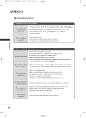
... correct remote operating mode is weak, reorient antenna to -). Power interrupted. I Is the power cord inserted into the outlet where the product's power cord was plugged in. to receive weaker station. I Try another channel. I Station signal is set ? I Check your service center, if the picture has not appeared after switching on . MFL34797033-en-simple 1/20/04 12:34 AM Page 26 APPENDIX APPENDIX TROUBLESHOOTING The operation does not work . I Install new...
... correct remote operating mode is weak, reorient antenna to -). Power interrupted. I Is the power cord inserted into the outlet where the product's power cord was plugged in. to receive weaker station. I Try another channel. I Station signal is set ? I Check your service center, if the picture has not appeared after switching on . MFL34797033-en-simple 1/20/04 12:34 AM Page 26 APPENDIX APPENDIX TROUBLESHOOTING The operation does not work . I Install new...
Owner's Manual (English)
Page 31
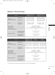
.../04 12:34 AM Page 29 APPENDIX PRODUCT SPECIFICATIONS MODELS Dimensions (Width x Height x Depth) Including stand Excluding stand Weight including stand excluding stand Power requirement Television System Program Coverage External Antenna Impedance Environment condition Operating Temperature Operating Humidity Storage Temperature Storage Humidity 42PC5D (42PC5D-UL) 42PC5DC (42PC5DC-UL) 41.3 x 30.2 x 12.2 inches 1048.0 x 766.0 x 310.0 mm 41.3 x 28.1 x 3.3 inches 1048.0 x 713.0 x 83.5 mm 50PC5D (50PC5D-UL) 50PC5DC...
.../04 12:34 AM Page 29 APPENDIX PRODUCT SPECIFICATIONS MODELS Dimensions (Width x Height x Depth) Including stand Excluding stand Weight including stand excluding stand Power requirement Television System Program Coverage External Antenna Impedance Environment condition Operating Temperature Operating Humidity Storage Temperature Storage Humidity 42PC5D (42PC5D-UL) 42PC5DC (42PC5DC-UL) 41.3 x 30.2 x 12.2 inches 1048.0 x 766.0 x 310.0 mm 41.3 x 28.1 x 3.3 inches 1048.0 x 713.0 x 83.5 mm 50PC5D (50PC5D-UL) 50PC5DC...


