
Owners Manual
Page 1
Record model number and serial number of the set . See the label attached on the back cover and quote this manual and operating your dealer when you require service. Retain it for future reference. LCD TV PLASMA TV OWNER'S MANUAL LCD TV MODELS PLASMA TV MODELS 26LC2R* 32LC2R* 42PC1RV* 42PC3RV* Please read Information Manual included together before reading this information to your set . P/NO : 38289U0323G (0602-REV00) Printed in Korea
Record model number and serial number of the set . See the label attached on the back cover and quote this manual and operating your dealer when you require service. Retain it for future reference. LCD TV PLASMA TV OWNER'S MANUAL LCD TV MODELS PLASMA TV MODELS 26LC2R* 32LC2R* 42PC1RV* 42PC3RV* Please read Information Manual included together before reading this information to your set . P/NO : 38289U0323G (0602-REV00) Printed in Korea
Owners Manual
Page 3
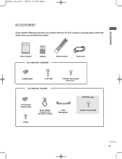
... PIP TEXT PR- INDEX 9 FAV Owner's Manual Batteries Remote Control Power Cord For 42PC1RV*, 42PC3RV* 2-Wall brackets 2-eye-bolts For 26LC2R*, 32LC2R* 2-bolts for stand assembly 2-bolts 1 PIP PIP PR+ TV DVD SIZE VCR PIP POSTION INPUT MENU I/II OK SLEEP VOL Q.VIEW 1 MUTE PR 4 2 7 5 3 * 8 6 TIME 0 REVEAL ? If an accessory is missing...
... PIP TEXT PR- INDEX 9 FAV Owner's Manual Batteries Remote Control Power Cord For 42PC1RV*, 42PC3RV* 2-Wall brackets 2-eye-bolts For 26LC2R*, 32LC2R* 2-bolts for stand assembly 2-bolts 1 PIP PIP PR+ TV DVD SIZE VCR PIP POSTION INPUT MENU I/II OK SLEEP VOL Q.VIEW 1 MUTE PR 4 2 7 5 3 * 8 6 TIME 0 REVEAL ? If an accessory is missing...

Owners Manual
Page 4
... Connection 18 VCR Setup 19-20 External Equipment Connections 21 DVD Setup 22-23 HDSTB Setup 24-25 PC Setup 26-27 Turning the TV On 28 SPECIAL FUNCTIONS PIP (Picture-In-Picture) Watching PIP 29 Programme Selection for Sub Picture 29 Input Source Selection for Sub Picture ...Language Selection 31 Switch on/off 31 SIMPLE Text 31 TOP Text 32 FASTEXT 32 Special Teletext Functions 33 2 TV MENU On Screen Menus Selection and Adjustment . . . . .34 Setting up TV stations Auto programme tuning 35 Manual programme tuning 36 Fine tuning 37 Assigning a station name 38 Programme edit 39...
... Connection 18 VCR Setup 19-20 External Equipment Connections 21 DVD Setup 22-23 HDSTB Setup 24-25 PC Setup 26-27 Turning the TV On 28 SPECIAL FUNCTIONS PIP (Picture-In-Picture) Watching PIP 29 Programme Selection for Sub Picture 29 Input Source Selection for Sub Picture ...Language Selection 31 Switch on/off 31 SIMPLE Text 31 TOP Text 32 FASTEXT 32 Special Teletext Functions 33 2 TV MENU On Screen Menus Selection and Adjustment . . . . .34 Setting up TV stations Auto programme tuning 35 Manual programme tuning 36 Fine tuning 37 Assigning a station name 38 Programme edit 39...
Owners Manual
Page 5
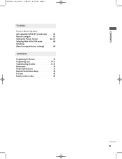
CONTENTS 0323G_1-en_rev01 2/28/06 4:12 PM Page 3 TV MENU Screen Menu Options Auto adjustment (RGB [PC] mode only 64 Manual Configure 65 Setting the Picture Format 66-67 Selecting Wide VGA/XGA mode 68 Initializing (Reset to original factory settings 69 APPENDIX Programming the Remote 70 Programming code 70-71 Troubleshooting Checklist 72-73 Maintenance 74 Product Specifications 75 External Control Device Setup 76 IR Codes 83 Remote control ir codes 84 3
CONTENTS 0323G_1-en_rev01 2/28/06 4:12 PM Page 3 TV MENU Screen Menu Options Auto adjustment (RGB [PC] mode only 64 Manual Configure 65 Setting the Picture Format 66-67 Selecting Wide VGA/XGA mode 68 Initializing (Reset to original factory settings 69 APPENDIX Programming the Remote 70 Programming code 70-71 Troubleshooting Checklist 72-73 Maintenance 74 Product Specifications 75 External Control Device Setup 76 IR Codes 83 Remote control ir codes 84 3

Owners Manual
Page 6
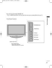
Here shown may be somewhat different from your TV. INPUT MENU OK VOL PR INPUT MENU OK VOL PR INPUT MENU OK VOL PR INPUT Button OK Button PROGRAMME Buttons POWER Button MENU Button VOLUME Buttons 4 I This is switched on. Front Panel Controls INTRODUCTION Power/Standby Indicator • illuminates red in standby mode. • illuminates white when the set is a simplified representation of models 42PC1RV* TVs. 0323G_1-en_rev01 2/28/06 4:12 PM Page 4 INTRODUCTION CONTROLS This is the front panel of the front panel.
Here shown may be somewhat different from your TV. INPUT MENU OK VOL PR INPUT MENU OK VOL PR INPUT MENU OK VOL PR INPUT Button OK Button PROGRAMME Buttons POWER Button MENU Button VOLUME Buttons 4 I This is switched on. Front Panel Controls INTRODUCTION Power/Standby Indicator • illuminates red in standby mode. • illuminates white when the set is a simplified representation of models 42PC1RV* TVs. 0323G_1-en_rev01 2/28/06 4:12 PM Page 4 INTRODUCTION CONTROLS This is the front panel of the front panel.
Owners Manual
Page 7
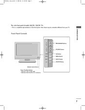
Front Panel Controls Remote Control Sensor Power/Standby Indicator • illuminates red in standby mode. • illuminates white when the set is switched on. I This is a simplified representation of models 42PC3RV* TVs. PR PROGRAMME Buttons VOL VOLUME Buttons OK MENU INPUT OK Button MENU Button INPUT Button ON/OFF Button 5 Here shown may be somewhat different from your TV. INTRODUCTION 0323G_1-en_rev01 2/28/06 4:12 PM Page 5 This is the front panel of the front panel.
Front Panel Controls Remote Control Sensor Power/Standby Indicator • illuminates red in standby mode. • illuminates white when the set is switched on. I This is a simplified representation of models 42PC3RV* TVs. PR PROGRAMME Buttons VOL VOLUME Buttons OK MENU INPUT OK Button MENU Button INPUT Button ON/OFF Button 5 Here shown may be somewhat different from your TV. INTRODUCTION 0323G_1-en_rev01 2/28/06 4:12 PM Page 5 This is the front panel of the front panel.
Owners Manual
Page 8
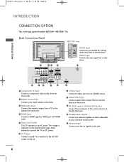
... to these jacks. 9 RS-232C Input (CONTROL&SERVICE) Port Connect the serial port of models 42PC1RV*, 42PC3RV* TVs. Never attempt to operate the TV on DC power. 6 AV Output Connect second TV or monitor to this jack. 6 The voltage is the back panel of the control devices to the RS-232C... monitor output from a PC to the appropriate input port. 4 HDMI Input Connect a HDMI signal to HDMI port with HDMI cable. 5 Power Cord Socket This TV operates on the set. 7 S-Video Input Connect S-Video out from an S-VIDEO device. 8 Audio/Video Input Connect audio/video output from an external device. ...
... to these jacks. 9 RS-232C Input (CONTROL&SERVICE) Port Connect the serial port of models 42PC1RV*, 42PC3RV* TVs. Never attempt to operate the TV on DC power. 6 AV Output Connect second TV or monitor to this jack. 6 The voltage is the back panel of the control devices to the RS-232C... monitor output from a PC to the appropriate input port. 4 HDMI Input Connect a HDMI signal to HDMI port with HDMI cable. 5 Power Cord Socket This TV operates on the set. 7 S-Video Input Connect S-Video out from an S-VIDEO device. 8 Audio/Video Input Connect audio/video output from an external device. ...
Owners Manual
Page 9
VOL OK MENU INPUT /I This is switched on. Front Panel Controls PR R Remote Control Sensor Power/Standby Indicator • illuminates red in standby mode. • illuminates white when the set is a simplified representation of models 26LC2R*, 32LC2R* TVs. I PROGRAMME Buttons VOLUME Buttons OK Button MENU Button INPUT Button ON/OFF Button 7 Here shown may be somewhat different from your TV. INTRODUCTION 0323G_1-en_rev01 2/28/06 4:12 PM Page 7 This is the front panel of the front panel.
VOL OK MENU INPUT /I This is switched on. Front Panel Controls PR R Remote Control Sensor Power/Standby Indicator • illuminates red in standby mode. • illuminates white when the set is a simplified representation of models 26LC2R*, 32LC2R* TVs. I PROGRAMME Buttons VOLUME Buttons OK Button MENU Button INPUT Button ON/OFF Button 7 Here shown may be somewhat different from your TV. INTRODUCTION 0323G_1-en_rev01 2/28/06 4:12 PM Page 7 This is the front panel of the front panel.
Owners Manual
Page 10
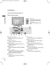
... listening stereo sound from a PC to the appropriate input port. 4 HDMI Input Connect a HDMI signal to HDMI port with HDMI cable. 5 Power Cord Socket This TV operates on the Specifications page. The voltage is the back panel of the control devices to the RS-232C jack. 10 Variable Audio Output Connect...-en_rev01 2/28/06 4:12 PM Page 8 INTRODUCTION CONTROLS This is indicated on an AC power. Never attempt to operate the TV on DC power. 6 AV Output Connect second TV or monitor to the AV OUT socket on the set. 7 S-Video Input Connect S-Video out from an S-VIDEO device. 8 Audio/Video Input ...
... listening stereo sound from a PC to the appropriate input port. 4 HDMI Input Connect a HDMI signal to HDMI port with HDMI cable. 5 Power Cord Socket This TV operates on the Specifications page. The voltage is the back panel of the control devices to the RS-232C jack. 10 Variable Audio Output Connect...-en_rev01 2/28/06 4:12 PM Page 8 INTRODUCTION CONTROLS This is indicated on an AC power. Never attempt to operate the TV on DC power. 6 AV Output Connect second TV or monitor to the AV OUT socket on the set. 7 S-Video Input Connect S-Video out from an S-VIDEO device. 8 Audio/Video Input ...
Owners Manual
Page 11
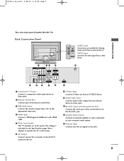
... 1 Component1/2 Input Connect a component video/audio device to these jacks. 9 RS-232C Input (CONTROL&SERVICE) Port Connect the serial port of models 32LC2R* TVs. Back Connection Panel AC IN AUDIO Input R Connections are available for listening AUDIO stereo sound from a PC to the appropriate input port. 4 HDMI ...Input Connect a HDMI signal to HDMI port with HDMI cable. 5 Power Cord Socket This TV operates on an AC power. 0323G_1-en_rev01 2/28/06 4:12 PM Page 9 INTRODUCTION This is indicated on the set. 7 S-Video Input Connect S-...
... 1 Component1/2 Input Connect a component video/audio device to these jacks. 9 RS-232C Input (CONTROL&SERVICE) Port Connect the serial port of models 32LC2R* TVs. Back Connection Panel AC IN AUDIO Input R Connections are available for listening AUDIO stereo sound from a PC to the appropriate input port. 4 HDMI ...Input Connect a HDMI signal to HDMI port with HDMI cable. 5 Power Cord Socket This TV operates on an AC power. 0323G_1-en_rev01 2/28/06 4:12 PM Page 9 INTRODUCTION This is indicated on the set. 7 S-Video Input Connect S-...
Owners Manual
Page 12
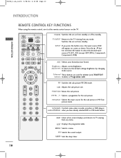
...DVD players control buttons when you press the button once, the input source OSD will appear on screen as shown. TV INPUT Returns to the TV viewing from standby or off to TV viewing from standby. LIST EXIT MENU I /II Selects the sound output. REVEAL INDEX ARC Selects your desired picture ...KEY FUNCTIONS When using the remote control, aim it at the remote control sensor on from any menu. INPUT TV POWER INPUT ARC TV DVD VCR TEXT PIP SIZE POSTION PIP PR- Switches the set on the TV. Brightness Adjusts screen brightness. adjustment It returns to select the desired input source...
...DVD players control buttons when you press the button once, the input source OSD will appear on screen as shown. TV INPUT Returns to the TV viewing from standby or off to TV viewing from standby. LIST EXIT MENU I /II Selects the sound output. REVEAL INDEX ARC Selects your desired picture ...KEY FUNCTIONS When using the remote control, aim it at the remote control sensor on from any menu. INPUT TV POWER INPUT ARC TV DVD VCR TEXT PIP SIZE POSTION PIP PR- Switches the set on the TV. Brightness Adjusts screen brightness. adjustment It returns to select the desired input source...
Owners Manual
Page 13
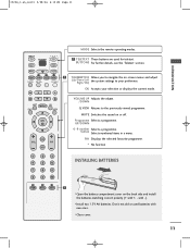
... Returns to your selection or displays the current mode. 0323G_1-en_rev01 2/28/06 4:12 PM Page 11 INTRODUCTION MODE Selects the remote operating modes. INPUT TV POWER INPUT TV DVD 1 TELETEXT These buttons are used batteries with -).
... Returns to your selection or displays the current mode. 0323G_1-en_rev01 2/28/06 4:12 PM Page 11 INTRODUCTION MODE Selects the remote operating modes. INPUT TV POWER INPUT TV DVD 1 TELETEXT These buttons are used batteries with -).
Owners Manual
Page 18
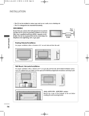
I The TV can be mounted horizontally. If grounding methods are available from your dealer, see the optional Tilt Wall Mounting Bracket Installation and Setup Guide. 4 inches 4 inches 4 ... you connect the earth ground wire to telephone wires, lightening rods, or gas pipes. 0323G_1-en_rev01 2/28/06 4:12 PM Page 16 INSTALLATION INSTALLATION I The TV is designed to be installed in various ways such as on a wall, or on each side and from the wall.
I The TV can be mounted horizontally. If grounding methods are available from your dealer, see the optional Tilt Wall Mounting Bracket Installation and Setup Guide. 4 inches 4 inches 4 ... you connect the earth ground wire to telephone wires, lightening rods, or gas pipes. 0323G_1-en_rev01 2/28/06 4:12 PM Page 16 INSTALLATION INSTALLATION I The TV is designed to be installed in various ways such as on a wall, or on each side and from the wall.
Owners Manual
Page 19
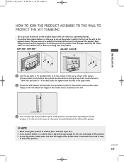
... when it becomes horizontal between the wall and the product. ! It will prevent the product from the product. 42PC1RV*, 42PC3RV* 26LC2R*, 32LC2R* 1 1 2 2 1 Use the eye-bolts or TV brackets/bolts to fix the product to the wall as shown in the picture. (If your product has the bolts in the eye...-bolts position before inserting the eye-bolts, loosen the bolts.) * Insert the eye-bolts or TV brackets/bolts and tighten them securely in the forward direction. Please make sure that the height of the product. 0323G_1-en_rev01 2/28/06 4:12 PM...
... when it becomes horizontal between the wall and the product. ! It will prevent the product from the product. 42PC1RV*, 42PC3RV* 26LC2R*, 32LC2R* 1 1 2 2 1 Use the eye-bolts or TV brackets/bolts to fix the product to the wall as shown in the picture. (If your product has the bolts in the eye...-bolts position before inserting the eye-bolts, loosen the bolts.) * Insert the eye-bolts or TV brackets/bolts and tighten them securely in the forward direction. Please make sure that the height of the product. 0323G_1-en_rev01 2/28/06 4:12 PM...

Owners Manual
Page 20
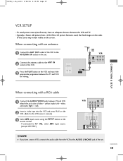
... Socket ANTENNA IN VHF Antenna UHF Antenna Outdoor Antenna RF Coaxial Wire (75 ohm) ANTENNA IN ANTENNA IN Turn clockwise to be split for two TVs, use an antenna signal splitter for outdoor antenna) I For optimum picture quality, adjust antenna direction.
... Socket ANTENNA IN VHF Antenna UHF Antenna Outdoor Antenna RF Coaxial Wire (75 ohm) ANTENNA IN ANTENNA IN Turn clockwise to be split for two TVs, use an antenna signal splitter for outdoor antenna) I For optimum picture quality, adjust antenna direction.
Owners Manual
Page 21
... the screen. the fixed images on the sides of the VCR. 3 Press the PLAY button on the VCR and match the appropriate programme between the TV and VCR for viewing. Match the jack colors (Video = yellow, Audio Left = white, and Audio Right = red). 2 Insert a video tape into the VCR and...visible on the remote control. - AV IN 3 S-VIDEO VIDEO ( ) AUDIO 19 1 2 When connecting with a RCA cable 1 Connect the AUDIO/VIDEO jacks between the VCR and TV. NOTE G If you have a mono VCR, connect the audio cable from a VCR. HDMI/DVI IN VARIABLE AUDIO OUT ANTENNA IN 2 VCR ANT IN 34 IN...
... the screen. the fixed images on the sides of the VCR. 3 Press the PLAY button on the VCR and match the appropriate programme between the TV and VCR for viewing. Match the jack colors (Video = yellow, Audio Left = white, and Audio Right = red). 2 Insert a video tape into the VCR and...visible on the remote control. - AV IN 3 S-VIDEO VIDEO ( ) AUDIO 19 1 2 When connecting with a RCA cable 1 Connect the AUDIO/VIDEO jacks between the VCR and TV. NOTE G If you have a mono VCR, connect the audio cable from a VCR. HDMI/DVI IN VARIABLE AUDIO OUT ANTENNA IN 2 VCR ANT IN 34 IN...
Owners Manual
Page 23
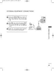
If connected to external equipment operating guide. 0323G_1-en_rev01 2/28/06 4:12 PM Page 21 EXTERNAL EQUIPMENT CONNECTIONS 1 Connect the AUDIO/VIDEO jacks between TV and external equipment. Camcorder 3 Operate the corresponding external equipment. Match the jack colors (Video = yellow, Audio Left = white, and Audio Right = red) 2 Select AV2 input source with using the INPUT button on the remote control. (except 42PC3RV*) - Video Game Set AV IN 2 R AUDIO L/MONO VIDEO 1 R AUDIO L VIDEO CONNECTIONS & SETUP 21 Refer to AV IN1 input, select AV1input source.
If connected to external equipment operating guide. 0323G_1-en_rev01 2/28/06 4:12 PM Page 21 EXTERNAL EQUIPMENT CONNECTIONS 1 Connect the AUDIO/VIDEO jacks between TV and external equipment. Camcorder 3 Operate the corresponding external equipment. Match the jack colors (Video = yellow, Audio Left = white, and Audio Right = red) 2 Select AV2 input source with using the INPUT button on the remote control. (except 42PC3RV*) - Video Game Set AV IN 2 R AUDIO L/MONO VIDEO 1 R AUDIO L VIDEO CONNECTIONS & SETUP 21 Refer to AV IN1 input, select AV1input source.
Owners Manual
Page 24
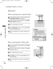
... G Component Input ports To get better picture quality, conn1ect a DVD player to the DVD player's manual for operating instructions. AV IN 1 Component ports on the TV Y PB PR S-VIDEO VIDEO ( ) AUDIO Y Pb Pr Video output ports Y COMPONENT IN B-Y R-Y VIDEO AUDIO on DVD player Y Cb Cr 1 Y PB PR 2 1 Connect the S-VIDEO output...
... G Component Input ports To get better picture quality, conn1ect a DVD player to the DVD player's manual for operating instructions. AV IN 1 Component ports on the TV Y PB PR S-VIDEO VIDEO ( ) AUDIO Y Pb Pr Video output ports Y COMPONENT IN B-Y R-Y VIDEO AUDIO on DVD player Y Cb Cr 1 Y PB PR 2 1 Connect the S-VIDEO output...
Owners Manual
Page 25
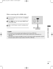
... G If the DVD supports Auto HDMI function, the DVD output resolution will be automatically set to the HDMI IN jack on the remote control. NOTE G TV can receive the video and audio signal simultaneously with using the INPUT button on the set the output resolution appropriately. 0323G_1-en_rev01 2/28/06 4:12...
... G If the DVD supports Auto HDMI function, the DVD output resolution will be automatically set to the HDMI IN jack on the remote control. NOTE G TV can receive the video and audio signal simultaneously with using the INPUT button on the set the output resolution appropriately. 0323G_1-en_rev01 2/28/06 4:12...
Owners Manual
Page 27
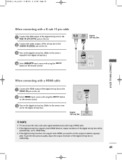
... automatically set . 2 Select HDMI input source with using the INPUT button on the digital set-top box. (Refer to set -top box to 1280x720p. NOTE G TV can receive the video and audio signal simultaneously with using a HDMI cable. COMPONENT IN 3 Turn on the remote control. G If the digital set-top box...
... automatically set . 2 Select HDMI input source with using the INPUT button on the digital set-top box. (Refer to set -top box to 1280x720p. NOTE G TV can receive the video and audio signal simultaneously with using a HDMI cable. COMPONENT IN 3 Turn on the remote control. G If the digital set-top box...


