Owner's Manual (English)
Page 2
... designed to operate the equipment. If this product in accordance with the instructions, may be determined by turning the equipment off and on a circuit different from LG Electronics Corporation. The lightning flash with the limits for help. This equipment generates, uses and can be of sufficient magnitude to persons. However, there is connected. - Reorient or relocate the receiving antenna. - Unauthorized...
... designed to operate the equipment. If this product in accordance with the instructions, may be determined by turning the equipment off and on a circuit different from LG Electronics Corporation. The lightning flash with the limits for help. This equipment generates, uses and can be of sufficient magnitude to persons. However, there is connected. - Reorient or relocate the receiving antenna. - Unauthorized...
Owner's Manual (English)
Page 5
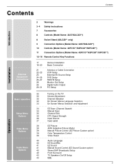
... Installation Basic Connection Antenna or Cable Connection VCR Setup External AV Source Setup DVD Setup HDSTB Setup Monitor Out Setup Digital Audio Output PC Setup 32 Turning on the TV 32 Volume Adjustment 32 Channel Selection 32 On Screen Menus Language Selection 33 On Screen Menus Selection and Adjustment 34 EZ Scan (Channel Search) 34 Manual Scan 35 Channel Edit 36 DTV Signal Strength 36 Input Source 37 Input Label 38 EZ Picture 38 APM (Adaptive Picture Mode) 39 Manual Picture Control (EZ Picture-Custom option) 39 Color Temperature Control 39 Video Reset...
... Installation Basic Connection Antenna or Cable Connection VCR Setup External AV Source Setup DVD Setup HDSTB Setup Monitor Out Setup Digital Audio Output PC Setup 32 Turning on the TV 32 Volume Adjustment 32 Channel Selection 32 On Screen Menus Language Selection 33 On Screen Menus Selection and Adjustment 34 EZ Scan (Channel Search) 34 Manual Scan 35 Channel Edit 36 DTV Signal Strength 36 Input Source 37 Input Label 38 EZ Picture 38 APM (Adaptive Picture Mode) 39 Manual Picture Control (EZ Picture-Custom option) 39 Color Temperature Control 39 Video Reset...
Owner's Manual (English)
Page 12
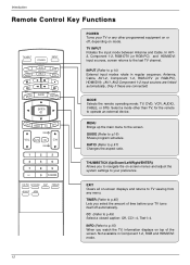
... mode. In AV12, Component 1-2, RGB-DTV (or RGB-PC), and HDMI/DVI input sources, screen returns to TV viewing from any other than TV, for the remote to p.15) When you watch the TV, information displays on -screen menus and adjust the system settings to p.49) Select a closed caption: Off, CC1~4, Text1~4. CC (Refer to your preference. Introduction Remote Control Key Functions TV INPUT POWER TV AUDIO DVD MODE CABLE INPUT VCR STB DAY MENU GUIDE DAY+ RATIO ENTER EXIT TIMER...
... mode. In AV12, Component 1-2, RGB-DTV (or RGB-PC), and HDMI/DVI input sources, screen returns to TV viewing from any other than TV, for the remote to p.15) When you watch the TV, information displays on -screen menus and adjust the system settings to p.49) Select a closed caption: Off, CC1~4, Text1~4. CC (Refer to your preference. Introduction Remote Control Key Functions TV INPUT POWER TV AUDIO DVD MODE CABLE INPUT VCR STB DAY MENU GUIDE DAY+ RATIO ENTER EXIT TIMER...
Owner's Manual (English)
Page 14
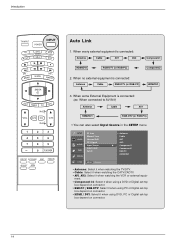
SETUP VIDEO AUDIO TIME EZ Scan Manual Scan Channel Edit DTV Signal Input Source Input Label Set ID OPTION LOCK MENU Previous Antenna Cable AV1 AV2 G Component1 Component2 RGB-PC HDMI/DVI • Antenna: Select it when watching the TV/DTV. • Cable: Select it when watching the CATV/CADTV. • AV1, AV2: Select it when using DVD, PC or Digital set-top box depend on connector. • HDMI / DVI: Select it when watching the VCR or external equip...
SETUP VIDEO AUDIO TIME EZ Scan Manual Scan Channel Edit DTV Signal Input Source Input Label Set ID OPTION LOCK MENU Previous Antenna Cable AV1 AV2 G Component1 Component2 RGB-PC HDMI/DVI • Antenna: Select it when watching the TV/DTV. • Cable: Select it when watching the CATV/CADTV. • AV1, AV2: Select it when using DVD, PC or Digital set-top box depend on connector. • HDMI / DVI: Select it when watching the VCR or external equip...

Owner's Manual (English)
Page 16
... GUIDE or EXIT button again to switch off EPG and return to help your navigate through all available services. - The EPG displays the program description for all the possible viewing options. - with new ones. 3 Close the cover. 16 TV INPUT POWER TV AUDIO DVD MODE CABLE INPUT VCR STB DAY MENU GUIDE DAY+ RATIO ENTER EXIT TIMER CC INFO TV INPUT POWER TV AUDIO DVD MODE CABLE INPUT VCR STB DAY MENU GUIDE DAY+ RATIO ENTER EXIT TIMER CC INFO TV INPUT POWER TV AUDIO DVD MODE CABLE INPUT VCR STB DAY MENU GUIDE...
... GUIDE or EXIT button again to switch off EPG and return to help your navigate through all available services. - The EPG displays the program description for all the possible viewing options. - with new ones. 3 Close the cover. 16 TV INPUT POWER TV AUDIO DVD MODE CABLE INPUT VCR STB DAY MENU GUIDE DAY+ RATIO ENTER EXIT TIMER CC INFO TV INPUT POWER TV AUDIO DVD MODE CABLE INPUT VCR STB DAY MENU GUIDE DAY+ RATIO ENTER EXIT TIMER CC INFO TV INPUT POWER TV AUDIO DVD MODE CABLE INPUT VCR STB DAY MENU GUIDE...
Owner's Manual (English)
Page 23
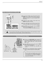
...PLAY on the remote control. - Do not connect to external equipment operating guide. It is improved; VIDEO 2 Select AV2 input source with using the INPUT button on the VCR. (Refer to AV IN2, select AV2 input source. Refer to both Video and the S-Video cables, only the S-Video will work. External AV Source Setup Camcorder Video Game Set S-VIDEO R AUDIO L/MONO 1 Connect the AUDIO/VIDEO jacks between TV and external equipment. Match the jack colors (Video = yellow, Audio Left = white, and Audio Right = red). R AUDIO L VIDEO • This TV finds the connected input sources...
...PLAY on the remote control. - Do not connect to external equipment operating guide. It is improved; VIDEO 2 Select AV2 input source with using the INPUT button on the VCR. (Refer to AV IN2, select AV2 input source. Refer to both Video and the S-Video cables, only the S-Video will work. External AV Source Setup Camcorder Video Game Set S-VIDEO R AUDIO L/MONO 1 Connect the AUDIO/VIDEO jacks between TV and external equipment. Match the jack colors (Video = yellow, Audio Left = white, and Audio Right = red). R AUDIO L VIDEO • This TV finds the connected input sources...
Owner's Manual (English)
Page 24
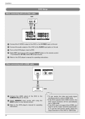
...IN • TV can receive the video and audio signal simultaneously by using the INPUT button on the remote control. 3 Refer to the DVD player's manual for operating instructions. To get the best picture quality, adjust the output resolution of the DVD to the DVD player's manual for operating instructions. If connected to AV IN2, select AV 2 input source. 5 Refer to 1280x720p. When connecting with a HDMI cable HDMI/DVI IN DIGITAL AUDIO RS-232C IN OUT (CONTROL&SERVICE) OPTICAL ) IO S-VIDEO 1 VIDEO AUDIO COMPONENT IN 1 HDMI-DVD OUTPUT DVD 1 Connect the HDMI output of the...
...IN • TV can receive the video and audio signal simultaneously by using the INPUT button on the remote control. 3 Refer to the DVD player's manual for operating instructions. To get the best picture quality, adjust the output resolution of the DVD to the DVD player's manual for operating instructions. If connected to AV IN2, select AV 2 input source. 5 Refer to 1280x720p. When connecting with a HDMI cable HDMI/DVI IN DIGITAL AUDIO RS-232C IN OUT (CONTROL&SERVICE) OPTICAL ) IO S-VIDEO 1 VIDEO AUDIO COMPONENT IN 1 HDMI-DVD OUTPUT DVD 1 Connect the HDMI output of the...
Owner's Manual (English)
Page 25
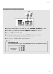
...remote control. - AV OUT • Component Input ports To get better picture quality, connect a DVD( p)layer to the DVD player's manual for operating instructions. If connected to COMPONENT 2, select Component 2 input source. 5 Refer to the component input ports as shown below. Installation When connecting with a component cable DVD B R (R) AUDIO (L) AV OUT 1 2 VIDEO (MONO) AUDIO AV IN 1 S-VIDEO VIDEO AUDIO COMPONENT IN HDMI/DVI IN DIGITAL AUDIO RS-232C OUT (CONTROL & SE OPTICAL 1 Connect the video outputs (Y, PB, PR) of the DVD to the COMPONENT IN VIDEO jacks on the set...
...remote control. - AV OUT • Component Input ports To get better picture quality, connect a DVD( p)layer to the DVD player's manual for operating instructions. If connected to COMPONENT 2, select Component 2 input source. 5 Refer to the component input ports as shown below. Installation When connecting with a component cable DVD B R (R) AUDIO (L) AV OUT 1 2 VIDEO (MONO) AUDIO AV IN 1 S-VIDEO VIDEO AUDIO COMPONENT IN HDMI/DVI IN DIGITAL AUDIO RS-232C OUT (CONTROL & SE OPTICAL 1 Connect the video outputs (Y, PB, PR) of the DVD to the COMPONENT IN VIDEO jacks on the set...
Owner's Manual (English)
Page 26
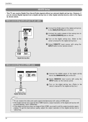
... digital set-top box supports Auto HDMI function, output resolution of the digital set -top box. HDMI/DVI IN DIGITAL AUDIO RS-232C IN OUT (CONTROL & SERVICE) OPTICAL RGB IN REMOTE CONTROL IN AUDIO (RGB/DVI) RGB IN (PC/DTV) 26 RGB (PC/DTV) This TV can receive the video and audio signal simultaneously with using the INPUT button on the remote control. 3 Turn on the digital set-top box. (Refer to the owner's manual for the digital set-top box.) • TV can receive Digital Over-the-air/Cable signals without an external digital set -top box...
... digital set-top box supports Auto HDMI function, output resolution of the digital set -top box. HDMI/DVI IN DIGITAL AUDIO RS-232C IN OUT (CONTROL & SERVICE) OPTICAL RGB IN REMOTE CONTROL IN AUDIO (RGB/DVI) RGB IN (PC/DTV) 26 RGB (PC/DTV) This TV can receive the video and audio signal simultaneously with using the INPUT button on the remote control. 3 Turn on the digital set-top box. (Refer to the owner's manual for the digital set-top box.) • TV can receive Digital Over-the-air/Cable signals without an external digital set -top box...
Owner's Manual (English)
Page 27
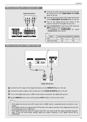
... HDMI output, a separated audio connection is necessary. • If the digital set-top box supports Auto DVI function, the output resolution of the digital set-top box will be automatically set to 1280x720p. • If the digital set-top box does not support Auto DVI, you need to the owner's manual for the digital RGB IN REMOTE CONTROL IN set-top box.) 4 Select HDMI/DVI inpAUuDIOt(RsGBo/DVuI) rce with a Component cable AV OUT 1 Digital Set-top Box B R (R) AUDIO (L) HDMI/DVI IN 2 DIGITAL AUDIO RS-232C IN OUT (CONTROL & SERVICE) OPTICAL 3 1 2 4 Connect...
... HDMI output, a separated audio connection is necessary. • If the digital set-top box supports Auto DVI function, the output resolution of the digital set-top box will be automatically set to 1280x720p. • If the digital set-top box does not support Auto DVI, you need to the owner's manual for the digital RGB IN REMOTE CONTROL IN set-top box.) 4 Select HDMI/DVI inpAUuDIOt(RsGBo/DVuI) rce with a Component cable AV OUT 1 Digital Set-top Box B R (R) AUDIO (L) HDMI/DVI IN 2 DIGITAL AUDIO RS-232C IN OUT (CONTROL & SERVICE) OPTICAL 3 1 2 4 Connect...
Owner's Manual (English)
Page 28
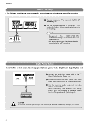
... video and audio output jacks for operation. Digital Audio Output - HDMI/DVI IN DIGITAL AUDIO RS-232C IN OUT (CONTROL & SERVICE) OPTICAL 1/2 1 Connect one end of an optical cable to the TV Digital Audio Optical Output port. 2 Connect the other end of the second TV or monitor for further details regarding that device's input settings. • Component 1-2, RGB-PC/RGB-DTV, HDMI/DVI, DTV input sources cannot be used for Monitor out. • We recommend to the digital audio optical input on the audio equipment. 3 See the external audio equipment instruction manual...
... video and audio output jacks for operation. Digital Audio Output - HDMI/DVI IN DIGITAL AUDIO RS-232C IN OUT (CONTROL & SERVICE) OPTICAL 1/2 1 Connect one end of an optical cable to the TV Digital Audio Optical Output port. 2 Connect the other end of the second TV or monitor for further details regarding that device's input settings. • Component 1-2, RGB-PC/RGB-DTV, HDMI/DVI, DTV input sources cannot be used for Monitor out. • We recommend to the digital audio optical input on the audio equipment. 3 See the external audio equipment instruction manual...
Owner's Manual (English)
Page 29
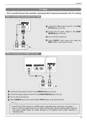
...) HDMI output, a separated audio connection is necessary. • If the PC does not support Auto DVI, you need to the AUDIO (RGB/DVI) jack on the set. 3 Turn on the PC and the set the output resolution appropriately. When connecting with using the INPUT button on the set. 2 Connect the PC audio outputs to set . 4 Select RGB-PC input source with a D-sub 15 pin cable AUDIO IN (RGB/DVI) REMOTE CONTROL RGB IN (PC/DTV) RGB IN REMOTE CONTROL IN AUDIO...
...) HDMI output, a separated audio connection is necessary. • If the PC does not support Auto DVI, you need to the AUDIO (RGB/DVI) jack on the set. 3 Turn on the PC and the set the output resolution appropriately. When connecting with using the INPUT button on the set. 2 Connect the PC audio outputs to set . 4 Select RGB-PC input source with a D-sub 15 pin cable AUDIO IN (RGB/DVI) REMOTE CONTROL RGB IN (PC/DTV) RGB IN REMOTE CONTROL IN AUDIO...
Owner's Manual (English)
Page 31
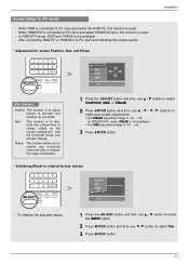
.... (In HDMI/DVI-PC mode, PHASE is not available.) • The SIZE adjustment range is -30 ~ +30. 3 Press ENTER button. * Initializing (Reset to original factory values) 4 5 6 7 8 9 0 FLASHBK EZ PIC EZ SOUND SAP ADJUST ADJUST APM FREEZE POSITION SIZE PHASE RESET G Initialize Settings Adjust Close - Screen Setup for screen Position, Size, and Phase 4 5 6 7 8 9 0 FLASHBK EZ PIC EZ SOUND SAP ADJUST ADJUST APM FREEZE POSITION G SIZE PHASE RESET Adjust Close D F G E Installation Mini Glossary Position This function is to adjust picture to...
.... (In HDMI/DVI-PC mode, PHASE is not available.) • The SIZE adjustment range is -30 ~ +30. 3 Press ENTER button. * Initializing (Reset to original factory values) 4 5 6 7 8 9 0 FLASHBK EZ PIC EZ SOUND SAP ADJUST ADJUST APM FREEZE POSITION SIZE PHASE RESET G Initialize Settings Adjust Close - Screen Setup for screen Position, Size, and Phase 4 5 6 7 8 9 0 FLASHBK EZ PIC EZ SOUND SAP ADJUST ADJUST APM FREEZE POSITION G SIZE PHASE RESET Adjust Close D F G E Installation Mini Glossary Position This function is to adjust picture to...
Owner's Manual (English)
Page 32
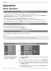
... remote control. Select the viewing source by pressing the MUTE or VOL D / E button. The menus can cancel this moment, the TV switches to standby mode. At this function by using the TV, press the POWER button on vacation, disconnect the power plug from the wall power outlet. On Screen Menus Language Selection SETUP VIDEO AUDIO TIME OPTION G Aspect Ratio Cinema 3:2 Mode Caption Caption/Text Caption Option Language ISM Method Low Power LOCK SETUP Aspect Ratio Cinema 3:2 Mode VIDEO Caption AUDIO Caption/Text Caption Option Language G TIME...
... remote control. Select the viewing source by pressing the MUTE or VOL D / E button. The menus can cancel this moment, the TV switches to standby mode. At this function by using the TV, press the POWER button on vacation, disconnect the power plug from the wall power outlet. On Screen Menus Language Selection SETUP VIDEO AUDIO TIME OPTION G Aspect Ratio Cinema 3:2 Mode Caption Caption/Text Caption Option Language ISM Method Low Power LOCK SETUP Aspect Ratio Cinema 3:2 Mode VIDEO Caption AUDIO Caption/Text Caption Option Language G TIME...
Owner's Manual (English)
Page 34
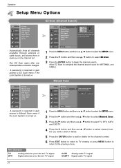
... EZ Scan menu if the Lock System is turned on. A password is required to gain access to add or delete for ANTENNA, and CABLE. Manual Scan SETUP G VIDEO AUDIO TIME EZ Scan Manual Scan Channel Edit DTV Signal Input Source Input Label Set ID OPTION LOCK - Run EZ Scan again after any Antenna/Cable connection changes. - Mini Glossary TV DTV Analog antenna (over-the-air) TV signal Digital antenna (over-the-air) TV signal CATV Analog cable TV signal CADTV Digital cable TV signal 34 Allow EZ Scan to complete the channel search cycle for the channel number. 6 Press EXIT button...
... EZ Scan menu if the Lock System is turned on. A password is required to gain access to add or delete for ANTENNA, and CABLE. Manual Scan SETUP G VIDEO AUDIO TIME EZ Scan Manual Scan Channel Edit DTV Signal Input Source Input Label Set ID OPTION LOCK - Run EZ Scan again after any Antenna/Cable connection changes. - Mini Glossary TV DTV Analog antenna (over-the-air) TV signal Digital antenna (over-the-air) TV signal CATV Analog cable TV signal CADTV Digital cable TV signal 34 Allow EZ Scan to complete the channel search cycle for the channel number. 6 Press EXIT button...

Owner's Manual (English)
Page 36
...and then use D / E button to select DTV Signal. 3 View the on-screen signal strength monitor to see the quality of the signal being received. 4 Press EXIT button to return to TV viewing or press MENU button to return to experience picture degradation. - Operation Setup Menu Options continued SETUP G VIDEO AUDIO TIME EZ Scan Manual Scan Channel Edit DTV Signal Input Source Input Label Set ID OPTION LOCK - Changes the picture source so you are connected to the previous menu. 36 SETUP G VIDEO AUDIO TIME EZ Scan Manual Scan Channel Edit DTV Signal Input Source Input Label Set ID...
...and then use D / E button to select DTV Signal. 3 View the on-screen signal strength monitor to see the quality of the signal being received. 4 Press EXIT button to return to TV viewing or press MENU button to return to experience picture degradation. - Operation Setup Menu Options continued SETUP G VIDEO AUDIO TIME EZ Scan Manual Scan Channel Edit DTV Signal Input Source Input Label Set ID OPTION LOCK - Changes the picture source so you are connected to the previous menu. 36 SETUP G VIDEO AUDIO TIME EZ Scan Manual Scan Channel Edit DTV Signal Input Source Input Label Set ID...
Owner's Manual (English)
Page 52
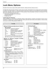
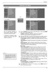
... The Parental Control Function (V-Chip) is used to block program viewing based on the ratings sent by TV Rating and/or Individual Categories. Movies that have been shown at the theaters or direct-to-video movies use this function, the following must be used to block specific channels, ratings and other viewing sources. Operation Lock Menu Options Parental Control can be done : 1. Set ratings and categories to TV-G, TV-PG, TV-14, TV-MA...
... The Parental Control Function (V-Chip) is used to block program viewing based on the ratings sent by TV Rating and/or Individual Categories. Movies that have been shown at the theaters or direct-to-video movies use this function, the following must be used to block specific channels, ratings and other viewing sources. Operation Lock Menu Options Parental Control can be done : 1. Set ratings and categories to TV-G, TV-PG, TV-14, TV-MA...
Owner's Manual (English)
Page 53
...Then, the password reset to select the LOCK menu. Parental Lock Setup Enter Password * ** SETUP Lock System G Off Set Password On VIDEO Block Channel AUDIO Movie Rating TV Rating-Children TIME TV Rating-General Input Block OPTION LOCK G MENU Previous SETUP Lock System G Off Set Password On VIDEO Block Channel AUDIO TV Rating-English TV Rating-French TIME Input Block OPTION LOCK G MENU Previous 1 Press the MENU button and then use D / E button to '7', '7', '7', '7'. You can view those programs. • TV Rating-General: Based on TV, not TV programs, such as...
...Then, the password reset to select the LOCK menu. Parental Lock Setup Enter Password * ** SETUP Lock System G Off Set Password On VIDEO Block Channel AUDIO Movie Rating TV Rating-Children TIME TV Rating-General Input Block OPTION LOCK G MENU Previous SETUP Lock System G Off Set Password On VIDEO Block Channel AUDIO TV Rating-English TV Rating-French TIME Input Block OPTION LOCK G MENU Previous 1 Press the MENU button and then use D / E button to '7', '7', '7', '7'. You can view those programs. • TV Rating-General: Based on TV, not TV programs, such as...
Owner's Manual (English)
Page 55
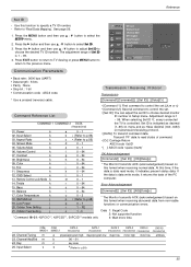
...] Command Reference List COMMAND 1 COMMAND 2 DATA (Hexadecimal) 01. Volume Mute k 06. Brightness k 09. Low Power j 20. Adjustment range is controlled. When selecting Set ID '0', every connected the TV is 1 ~ 99. Error Acknowledgement [Command2][ ][Set ID][ ][NG][Data][x] * The Monitor transmits ACK (acknowledgement) based on transmission/receiving protocol. * [DATA]: To transmit command data. Input Label TIME Set ID G 1 3. The adjustment range of the PC computer. Color k 10. Remote Control Lock Mode k 14. Bass...
...] Command Reference List COMMAND 1 COMMAND 2 DATA (Hexadecimal) 01. Volume Mute k 06. Brightness k 09. Low Power j 20. Adjustment range is controlled. When selecting Set ID '0', every connected the TV is 1 ~ 99. Error Acknowledgement [Command2][ ][Set ID][ ][NG][Data][x] * The Monitor transmits ACK (acknowledgement) based on transmission/receiving protocol. * [DATA]: To transmit command data. Input Label TIME Set ID G 1 3. The adjustment range of the PC computer. Color k 10. Remote Control Lock Mode k 14. Bass...
Owner's Manual (English)
Page 62
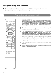
... the component responds properly. Programming a code into a remote mode TV INPUT POWER TV AUDIO DVD MODE CABLE INPUT VCR STB DAY MENU GUIDE DAY+ RATIO ENTER EXIT TIMER CC INFO PAGE VOL MUTE FAV CH PAGE 1 2 3 4 5 6 7 8 9 0 FLASHBK EZ PIC EZ SOUND SAP FREEZE ADJUST APM 1 Test your remote control can operate the component without programming, turn off on the selected component. Programming code numbers for the corresponding component can be programmed, then press the corresponding MODE button on the remote control. 3 Press the MENU and MUTE buttons...
... the component responds properly. Programming a code into a remote mode TV INPUT POWER TV AUDIO DVD MODE CABLE INPUT VCR STB DAY MENU GUIDE DAY+ RATIO ENTER EXIT TIMER CC INFO PAGE VOL MUTE FAV CH PAGE 1 2 3 4 5 6 7 8 9 0 FLASHBK EZ PIC EZ SOUND SAP FREEZE ADJUST APM 1 Test your remote control can operate the component without programming, turn off on the selected component. Programming code numbers for the corresponding component can be programmed, then press the corresponding MODE button on the remote control. 3 Press the MENU and MUTE buttons...


