Owners Manual
Page 8
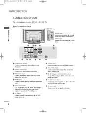
...* only AV IN 2 AUDIO Input R Connections are available for listening AUDIO stereo sound from a PC to the appropriate input port. 4 HDMI Input Connect a HDMI signal to this jack. 6 The voltage is the back panel of the control devices to the RS-232C jack. 10 Variable Audio Output ...an external device to these jacks. 2 Remote Control Port Connect your surround sound system. 11 Antenna Input Connect over-the-air signals to HDMI port with HDMI cable. 5 Power Cord Socket This TV operates on the Specifications page. 0323G_1-en_rev01 2/28/06 4:12 PM Page 6 INTRODUCTION INTRODUCTION ...
...* only AV IN 2 AUDIO Input R Connections are available for listening AUDIO stereo sound from a PC to the appropriate input port. 4 HDMI Input Connect a HDMI signal to this jack. 6 The voltage is the back panel of the control devices to the RS-232C jack. 10 Variable Audio Output ...an external device to these jacks. 2 Remote Control Port Connect your surround sound system. 11 Antenna Input Connect over-the-air signals to HDMI port with HDMI cable. 5 Power Cord Socket This TV operates on the Specifications page. 0323G_1-en_rev01 2/28/06 4:12 PM Page 6 INTRODUCTION INTRODUCTION ...
Owners Manual
Page 10
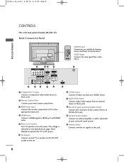
...system. 11 Antenna Input Connect over-the-air signals to these jacks. 9 RS-232C Input (CONTROL&SERVICE) Port Connect the serial port of models 26LC2R* TVs. Never attempt to operate the TV on DC power. 6 AV Output Connect second TV or monitor to the AV OUT socket on the set...Connect S-Video out from an S-VIDEO device. 8 Audio/Video Input Connect audio/video output from a PC to the appropriate input port. 4 HDMI Input Connect a HDMI signal to HDMI port with HDMI cable. 5 Power Cord Socket This TV operates on the Specifications page. The voltage is the back panel of the control devices to...
...system. 11 Antenna Input Connect over-the-air signals to these jacks. 9 RS-232C Input (CONTROL&SERVICE) Port Connect the serial port of models 26LC2R* TVs. Never attempt to operate the TV on DC power. 6 AV Output Connect second TV or monitor to the AV OUT socket on the set...Connect S-Video out from an S-VIDEO device. 8 Audio/Video Input Connect audio/video output from a PC to the appropriate input port. 4 HDMI Input Connect a HDMI signal to HDMI port with HDMI cable. 5 Power Cord Socket This TV operates on the Specifications page. The voltage is the back panel of the control devices to...
Owners Manual
Page 11
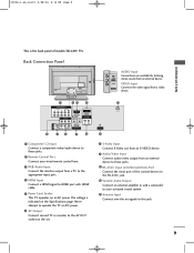
...your wired remote control here. 3 RGB/Audio Input Connect the monitor output from a PC to the appropriate input port. 4 HDMI Input Connect a HDMI signal to HDMI port with HDMI cable. 5 Power Cord Socket This TV operates on the Specifications page. Back Connection Panel AC IN AUDIO Input R Connections ...are available for listening AUDIO stereo sound from a video AV IN 2 device. 1 COMPONENT IN VIDEO AUDIO 1 2 AV OUT 23 4 RGB IN (PC/DTV) HDMI IN REMOTE AUDIO IN CONTROL IN (RGB) VARIABLE AUDIO OUT 5 AC IN AV IN 1 S-VIDEO VIDEO (MONO) AUDIO RS-232C IN (CONTROL & SERVICE) 6 ...
...your wired remote control here. 3 RGB/Audio Input Connect the monitor output from a PC to the appropriate input port. 4 HDMI Input Connect a HDMI signal to HDMI port with HDMI cable. 5 Power Cord Socket This TV operates on the Specifications page. Back Connection Panel AC IN AUDIO Input R Connections ...are available for listening AUDIO stereo sound from a video AV IN 2 device. 1 COMPONENT IN VIDEO AUDIO 1 2 AV OUT 23 4 RGB IN (PC/DTV) HDMI IN REMOTE AUDIO IN CONTROL IN (RGB) VARIABLE AUDIO OUT 5 AC IN AV IN 1 S-VIDEO VIDEO (MONO) AUDIO RS-232C IN (CONTROL & SERVICE) 6 ...
Owners Manual
Page 21
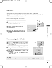
...). 2 Insert a video tape into the VCR and press PLAY on the remote control. - AV IN 3 S-VIDEO VIDEO ( ) AUDIO 19 1 2 If the 4:3 picture format is used; HDMI/DVI IN VARIABLE AUDIO OUT ANTENNA IN 2 VCR ANT IN 34 IN ANT OUT S-VIDEO OUT OUTPUT SWITCH (R) AUDIO (L) VIDEO 1 When connecting with an antenna...
...). 2 Insert a video tape into the VCR and press PLAY on the remote control. - AV IN 3 S-VIDEO VIDEO ( ) AUDIO 19 1 2 If the 4:3 picture format is used; HDMI/DVI IN VARIABLE AUDIO OUT ANTENNA IN 2 VCR ANT IN 34 IN ANT OUT S-VIDEO OUT OUTPUT SWITCH (R) AUDIO (L) VIDEO 1 When connecting with an antenna...
Owners Manual
Page 25
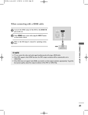
... receive the video and audio signal simultaneously with using the INPUT button on the set. 2 Select HDMI input source with a HDMI cable 1 Connect the HDMI output of the DVD to 1280x720p. G If the DVD does not support Auto HDMI, you need to set to 1280x720p. To get the best picture quality, adjust the output... resolution of the DVD to the DVD player's manual for operating instruc- tions. COMPONENT IN 3 Refer to the HDMI IN jack on the remote control. 0323G_1-en_rev01 2/28/06 4:12 PM Page 23 When connecting with using...
... receive the video and audio signal simultaneously with using the INPUT button on the set. 2 Select HDMI input source with a HDMI cable 1 Connect the HDMI output of the DVD to 1280x720p. G If the DVD does not support Auto HDMI, you need to set to 1280x720p. To get the best picture quality, adjust the output... resolution of the DVD to the DVD player's manual for operating instruc- tions. COMPONENT IN 3 Refer to the HDMI IN jack on the remote control. 0323G_1-en_rev01 2/28/06 4:12 PM Page 23 When connecting with using...

Owners Manual
Page 26
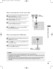
... 4 Select Component input source with using the INPUT button on the remote control. 1 2 AV IN 1 S-VIDEO VIDEO ( ) AUDIO RGB IN (PC/DTV) HDMI IN REMOTE AUDIO IN CONTROL IN (RGB) VARIABLE AUDIO OUT RS-232C IN (CONTROL&SERVICE) 1 2 Digital Set-top Box DVI-DTV OUTPUT (R) AUDIO (L) !.... 2 Connect the audio outputs of the digital set-top box to the owner's manual for the digital set -top box has a DVI output and no HDMI output, a separated audio connection is necessary. Digital Set-top Box B R (R) AUDIO (L) 1 2 COMPONENT IN VIDEO AUDIO 1 2 AV OUT ( MONO) S-VIDEO VIDEO ...
... 4 Select Component input source with using the INPUT button on the remote control. 1 2 AV IN 1 S-VIDEO VIDEO ( ) AUDIO RGB IN (PC/DTV) HDMI IN REMOTE AUDIO IN CONTROL IN (RGB) VARIABLE AUDIO OUT RS-232C IN (CONTROL&SERVICE) 1 2 Digital Set-top Box DVI-DTV OUTPUT (R) AUDIO (L) !.... 2 Connect the audio outputs of the digital set-top box to the owner's manual for the digital set -top box has a DVI output and no HDMI output, a separated audio connection is necessary. Digital Set-top Box B R (R) AUDIO (L) 1 2 COMPONENT IN VIDEO AUDIO 1 2 AV OUT ( MONO) S-VIDEO VIDEO ...
Owners Manual
Page 27
...-DTV input source with using the INPUT button on the remote control. (R) AUDIO (L) RGB-DTV OUTPUT Digital Set-top Box 2 1 RGB IN (PC/DTV) HDMI IN REMOTE AUDIO IN CONTROL IN (RGB) VARIABLE AUDIO OUT RS-232C IN (CONTROL&SERVICE) CONNECTIONS & SETUP When connecting with... a HDMI cable 1 Connect the HDMI output of the digital set-top box to the HDMI IN jack on the set the output resolution appropri- To get the best picture quality, adjust the output resolution...
...-DTV input source with using the INPUT button on the remote control. (R) AUDIO (L) RGB-DTV OUTPUT Digital Set-top Box 2 1 RGB IN (PC/DTV) HDMI IN REMOTE AUDIO IN CONTROL IN (RGB) VARIABLE AUDIO OUT RS-232C IN (CONTROL&SERVICE) CONNECTIONS & SETUP When connecting with... a HDMI cable 1 Connect the HDMI output of the digital set-top box to the HDMI IN jack on the set the output resolution appropri- To get the best picture quality, adjust the output resolution...
Owners Manual
Page 28
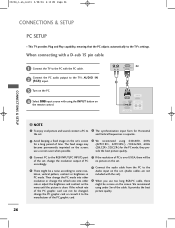
... the TV to the PC with using the INPUT button on the remote control. (R) AUDIO (L) RGB-DTV OUTPUT PC 2 1 RGB IN (PC/DTV) HDMI IN REMOTE AUDIO IN CONTROL IN (RGB) VARIABLE AUDIO OUT RS-232C IN (CONTROL&SERVICE) CONNECTIONS & SETUP ! and Vertical frequencies is separate. 2 Avoid ... not included with the set). 9 When you use a screen saver when possible. 6 We recommend using 640x480, 60Hz (42PC1RV*, 42PC3RV*) /1024x768, 60Hz (26LC2R*, 32LC2R*) for the PC mode, they provide the best picture quality. 3 Connect PC to 5 The synchronization input form for a long period of the cable.
... the TV to the PC with using the INPUT button on the remote control. (R) AUDIO (L) RGB-DTV OUTPUT PC 2 1 RGB IN (PC/DTV) HDMI IN REMOTE AUDIO IN CONTROL IN (RGB) VARIABLE AUDIO OUT RS-232C IN (CONTROL&SERVICE) CONNECTIONS & SETUP ! and Vertical frequencies is separate. 2 Avoid ... not included with the set). 9 When you use a screen saver when possible. 6 We recommend using 640x480, 60Hz (42PC1RV*, 42PC3RV*) /1024x768, 60Hz (26LC2R*, 32LC2R*) for the PC mode, they provide the best picture quality. 3 Connect PC to 5 The synchronization input form for a long period of the cable.
Owners Manual
Page 31
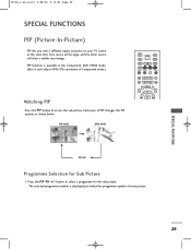
PIP function is displayed just below . The selected programme number is available in the Component, RGB, HDMI mode. (But, it can't adjust 480i/576i resolution of main picture. One source will be large, and the other source will show a smaller inset image. ...
PIP function is displayed just below . The selected programme number is available in the Component, RGB, HDMI mode. (But, it can't adjust 480i/576i resolution of main picture. One source will be large, and the other source will show a smaller inset image. ...
Owners Manual
Page 50
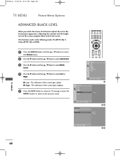
This function works in the following mode: AV (NTSC-M), SVideo (NTSC-M) or HDMI. 1 Press the M E N U button and then D / E button to select the Picture menu. 2 Press the G button and then D / E button to select Advanced. 3 Press the G button and then D / E ...
This function works in the following mode: AV (NTSC-M), SVideo (NTSC-M) or HDMI. 1 Press the M E N U button and then D / E button to select the Picture menu. 2 Press the G button and then D / E button to select Advanced. 3 Press the G button and then D / E ...
Owners Manual
Page 56
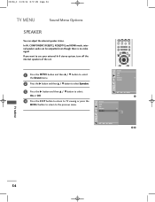
...-fi stereo system, turn off the internal speakers of the set. TEXT PIP SIZE POSTION PIP PR- In AV, COMPONENT, RGB[PC], RGB[DTV] and HDMI mode, internal speaker audio can adjust the internal speaker status. 0323G_2 2/22/06 8:57 PM Page 54 TV MENU Sound Menu Options SPEAKER You can...
...-fi stereo system, turn off the internal speakers of the set. TEXT PIP SIZE POSTION PIP PR- In AV, COMPONENT, RGB[PC], RGB[DTV] and HDMI mode, internal speaker audio can adjust the internal speaker status. 0323G_2 2/22/06 8:57 PM Page 54 TV MENU Sound Menu Options SPEAKER You can...
Owners Manual
Page 78
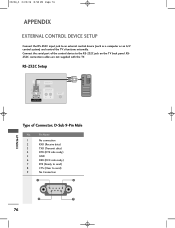
... device (such as a computer or an A/V control system) and control the TV's functions externally. D-Sub 9-Pin Male No. RS-232C Setup RGB IN (PC/DTV) HDMI/DVI IN REMOTE AUDIO IN CONTROL IN (RGB/DVI) VARIABLE AUDIO OUT RS-232C IN (CONTROL&SERVICE) UPGRADE (MODULE) PC RGB IN (PC/DTV...) HDMI/DVI IN VARIABLE AUDIO OUT Type of the control device to the RS-232C jack on the TV back pane l.RS232C connection cables are not ...
... device (such as a computer or an A/V control system) and control the TV's functions externally. D-Sub 9-Pin Male No. RS-232C Setup RGB IN (PC/DTV) HDMI/DVI IN REMOTE AUDIO IN CONTROL IN (RGB/DVI) VARIABLE AUDIO OUT RS-232C IN (CONTROL&SERVICE) UPGRADE (MODULE) PC RGB IN (PC/DTV...) HDMI/DVI IN VARIABLE AUDIO OUT Type of the control device to the RS-232C jack on the TV back pane l.RS232C connection cables are not ...

Service Manual
Page 17
... Bar) (3) Push the button change and select the Channel memory data (4) Check the communication is OK message. (5) Push the Update NVM from File b. Never connect HDMI & D-SUB Cable at the same time. - Use the proper cables below for EDID Download * Caution: - Colorcarrier Adjustment (inspection process) a. push the "adj" key in the...
... Bar) (3) Push the button change and select the Channel memory data (4) Check the communication is OK message. (5) Push the Update NVM from File b. Never connect HDMI & D-SUB Cable at the same time. - Use the proper cables below for EDID Download * Caution: - Colorcarrier Adjustment (inspection process) a. push the "adj" key in the...
Service Manual
Page 18
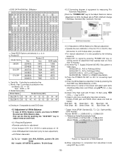
< EDID DATA HDMI Set : 256bytes> 4.3.2 Connecting diagram of equipment for measuring (For Automatic Adjustment) [Push the "POWER ON" key at the Adjust Remocon before Adjustment of White Balance 8) ... 30057(A) 7569 30058(D) 756A 37LC2R 30059(A) 756B 30060(D) 756C EDID table 1D56 1E56 6975 6A75 6B75 6C75 b. Model Name(Hex) : Model Name Model Name(HEX) 26LC2R-TJ 32 36 4C 43 32 52 2D 54 4A 32LC2R-TJ 33 32 4C 43 32 52 2D 54 4A e.Checksum: Changeable by pushing...
< EDID DATA HDMI Set : 256bytes> 4.3.2 Connecting diagram of equipment for measuring (For Automatic Adjustment) [Push the "POWER ON" key at the Adjust Remocon before Adjustment of White Balance 8) ... 30057(A) 7569 30058(D) 756A 37LC2R 30059(A) 756B 30060(D) 756C EDID table 1D56 1E56 6975 6A75 6B75 6C75 b. Model Name(Hex) : Model Name Model Name(HEX) 26LC2R-TJ 32 36 4C 43 32 52 2D 54 4A 32LC2R-TJ 33 32 4C 43 32 52 2D 54 4A e.Checksum: Changeable by pushing...

Service Manual
Page 25
... Yes Are Speaker units good? 2) Main board part Is sound at Scart1/2 (or No Component2)RGB, or Side AV Good? Exchange IC401 Is sound at HDMI No Good? No If it dead or short, exchange this elements - 25 - No Are Speaker Cables connect normally? Are good some elements (C, R, L, or Diode) at...
... Yes Are Speaker units good? 2) Main board part Is sound at Scart1/2 (or No Component2)RGB, or Side AV Good? Exchange IC401 Is sound at HDMI No Good? No If it dead or short, exchange this elements - 25 - No Are Speaker Cables connect normally? Are good some elements (C, R, L, or Diode) at...

Service Manual
Page 27
... Download the EDID data Exchange AD9381 IC Exchange the VCT-P IC - 27 - Check the EDID data No No No Yes Is AD9381 good? Yes (only _ HDMI) No Is VCT-P IC good? No picture (1) Symptom 1) Some mode doesn't display. 2) Front LED is green 3) The set still discharge a little (2) Check ...Is VCT-P IC good? 7. connected? No Insert the LVDS cable exactly Insert the Tuner cable exactly If it dead or short, exchange this elements 3) RGB/HDMI-mode doesn' Exchange the VCT-P IC Is the LVDS cable Yes connected? Are good some Yes elements (C, R, L, or Diode) at path? No Is ...
... Download the EDID data Exchange AD9381 IC Exchange the VCT-P IC - 27 - Check the EDID data No No No Yes Is AD9381 good? Yes (only _ HDMI) No Is VCT-P IC good? No picture (1) Symptom 1) Some mode doesn't display. 2) Front LED is green 3) The set still discharge a little (2) Check ...Is VCT-P IC good? 7. connected? No Insert the LVDS cable exactly Insert the Tuner cable exactly If it dead or short, exchange this elements 3) RGB/HDMI-mode doesn' Exchange the VCT-P IC Is the LVDS cable Yes connected? Are good some Yes elements (C, R, L, or Diode) at path? No Is ...

Service Manual
Page 28
TV_LV/R out MNT_V/L/R out TV_L/R MNT_L/R H/P_L/R SPK_L/R HDMI P600(LPL) LVDS_JAE P601(PDP) JAE STRAIGHT P602(CMO) LVDS_JAE LVDS VGA_R/G/B HS SC 1_R,G,B,FB (COMP 2 Y,PB,PR) COMP 1 Y,PB,PR SIDE_V SC 2_V, ... V-OUT GND 33V 5V SDA SCL AS +B TUNER TU1 RFA AV1 (FULL) AV2 (HALF) S-VIDEO AV3 (REAR AV) COMPONENT 1 WIRED IR PC A-IN RS-232C HDMI VAR.AUD.OUT PDP D/L RF INPUT BLOCK DIAGRAM - 28 -
TV_LV/R out MNT_V/L/R out TV_L/R MNT_L/R H/P_L/R SPK_L/R HDMI P600(LPL) LVDS_JAE P601(PDP) JAE STRAIGHT P602(CMO) LVDS_JAE LVDS VGA_R/G/B HS SC 1_R,G,B,FB (COMP 2 Y,PB,PR) COMP 1 Y,PB,PR SIDE_V SC 2_V, ... V-OUT GND 33V 5V SDA SCL AS +B TUNER TU1 RFA AV1 (FULL) AV2 (HALF) S-VIDEO AV3 (REAR AV) COMPONENT 1 WIRED IR PC A-IN RS-232C HDMI VAR.AUD.OUT PDP D/L RF INPUT BLOCK DIAGRAM - 28 -

Service Manual
Page 29
- 29 - CABLE IR RS232 RGB (PC/DTV) PC_Audio RF MNT_OUT S-AV AV COMP 1 RT COMP 2 SCART 1 RZ SCART 2 HDMI (PC/DTV) Variable Audio_out TX IR Tx 0/1 Rx 0/1 ST3232C TXD/RXD SCL/SDA 24C02 COMP1_Y/Pb/Pr VGA_RGB COMP2_Y/Pb/Pr VGA_HS/VS HDMI_HS/VS ...
- 29 - CABLE IR RS232 RGB (PC/DTV) PC_Audio RF MNT_OUT S-AV AV COMP 1 RT COMP 2 SCART 1 RZ SCART 2 HDMI (PC/DTV) Variable Audio_out TX IR Tx 0/1 Rx 0/1 ST3232C TXD/RXD SCL/SDA 24C02 COMP1_Y/Pb/Pr VGA_RGB COMP2_Y/Pb/Pr VGA_HS/VS HDMI_HS/VS ...


