
Service Manual
Page 21
... a vehicle, it . (4) Removing the printer Observe the following precautions in removal and transportation of the printer. • Be sure to repack the printer in its original carton. • Do not leave the printer, toner container, process unit and other printer modules inside when a vehicle is more than...the outdoor temperature is parked for a long period of time, the drum, toner container, process unit and the supplies should be exposed to the temperature change of the printer. 1-13 FS-1050 Allow approximately two to allow minimum air circulation or the adequate air conditioning ...
... a vehicle, it . (4) Removing the printer Observe the following precautions in removal and transportation of the printer. • Be sure to repack the printer in its original carton. • Do not leave the printer, toner container, process unit and other printer modules inside when a vehicle is more than...the outdoor temperature is parked for a long period of time, the drum, toner container, process unit and the supplies should be exposed to the temperature change of the printer. 1-13 FS-1050 Allow approximately two to allow minimum air circulation or the adequate air conditioning ...

Service Manual
Page 22
...-17 toner kit. FS-1050 1-14 To ensure the high print quality and long service life, the following handling precautions should use any refilled toner containers that may be available commercially. This is because Kyocera have no means of control over how such refilled toner could affect the print quality and the reliability of the printer. (1) Toner container...
...-17 toner kit. FS-1050 1-14 To ensure the high print quality and long service life, the following handling precautions should use any refilled toner containers that may be available commercially. This is because Kyocera have no means of control over how such refilled toner could affect the print quality and the reliability of the printer. (1) Toner container...

Service Manual
Page 23
... unit, put it in a protective bag and keep it with the toner container installed. Otherwise, toner may leak and contamination may result in the printer. 1-15 FS-1050 To ensure the high print quality, store the toner container in a place that satisfies the following environmental conditions: Temperature: -20 to 40 °C (-4 to 104 °F) Humidity: 15...
... unit, put it in a protective bag and keep it with the toner container installed. Otherwise, toner may leak and contamination may result in the printer. 1-15 FS-1050 To ensure the high print quality, store the toner container in a place that satisfies the following environmental conditions: Temperature: -20 to 40 °C (-4 to 104 °F) Humidity: 15...

Service Manual
Page 26
..., stable surface. Carefully remove the printer. Toner container (TK-17) Cleaning cloth Printer Installation guide Kyocera Mita digital library CD-ROM Figure 2-1-1 Unpacking (1) Power cord Remove the tape on the rear side of the spacer and remove the spacer. Tapes Spacer Printed notice Figure 2-1-2 Unpacking (2) 2-3 Spacer FS-1050 Remove the printer and all the accessories from the...
..., stable surface. Carefully remove the printer. Toner container (TK-17) Cleaning cloth Printer Installation guide Kyocera Mita digital library CD-ROM Figure 2-1-1 Unpacking (1) Power cord Remove the tape on the rear side of the spacer and remove the spacer. Tapes Spacer Printed notice Figure 2-1-2 Unpacking (2) 2-3 Spacer FS-1050 Remove the printer and all the accessories from the...

Service Manual
Page 27
For details, refer to the optional Paper feeder's Service Manual. 2-2-1 Installing the toner container 1. If the option paper feeder is in the release position. 1 Figure 2-2-1 Confirming the lock lever #1 FS-1050 2-4 If not, pull it forward until it is in the release (forward) position. Confirm that the lock lever #1 1 is used with the printer, begin installation with connecting the printer and the paper feeder. Open the top cover all the way. 2. Proceed as follows in sequence. 2-2 Installing the printer Installing the printer requires several steps.
For details, refer to the optional Paper feeder's Service Manual. 2-2-1 Installing the toner container 1. If the option paper feeder is in the release position. 1 Figure 2-2-1 Confirming the lock lever #1 FS-1050 2-4 If not, pull it forward until it is in the release (forward) position. Confirm that the lock lever #1 1 is used with the printer, begin installation with connecting the printer and the paper feeder. Open the top cover all the way. 2. Proceed as follows in sequence. 2-2 Installing the printer Installing the printer requires several steps.
Service Manual
Page 28
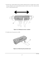
Hold it with the protective seal 3 (orange-colored) facing up. This ensures that the toner is evenly distributed inside. 2 Figure 2-2-2 Shaking the toner container 4. Carefully remove the protective seal 3. 3 Figure 2-2-3 Removing the protective seal 2-5 FS-1050 3. Shake the toner container 2 horizontally at least five times. Take the toner container 2 from the bag.
Hold it with the protective seal 3 (orange-colored) facing up. This ensures that the toner is evenly distributed inside. 2 Figure 2-2-2 Shaking the toner container 4. Carefully remove the protective seal 3. 3 Figure 2-2-3 Removing the protective seal 2-5 FS-1050 3. Shake the toner container 2 horizontally at least five times. Take the toner container 2 from the bag.
Service Manual
Page 29
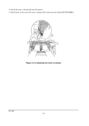
Install the toner container 2 into the printer. 6. 5. Push firmly on the top of the toner container 2 at the positions marked [PUSH HERE]. 2 Figure 2-2-4 Installing the toner container FS-1050 2-6
Install the toner container 2 into the printer. 6. 5. Push firmly on the top of the toner container 2 at the positions marked [PUSH HERE]. 2 Figure 2-2-4 Installing the toner container FS-1050 2-6

Service Manual
Page 30
... out once, shake it well, then install again. When the printer is approximately 15 minutes. If the toner low or replace toner indication does not go off after the toner container is necessary for the printer to the lock position. 8. FS-1050 2-7 The period of toner to print a job. 7. This delay is installed in its developer (Process unit...
... out once, shake it well, then install again. When the printer is approximately 15 minutes. If the toner low or replace toner indication does not go off after the toner container is necessary for the printer to the lock position. 8. FS-1050 2-7 The period of toner to print a job. 7. This delay is installed in its developer (Process unit...
Service Manual
Page 39
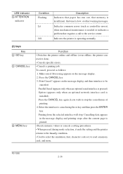
... when an optional serial interface is present) Option (appears only when an optional network interface card is low, or other warning messages. FS-1050 2-16 to cancel using the or key and then press the ENTER key. appears on the message display. 2. Printing from the selected... and offline (even offline, the printer can receive data). • Cancels specific errors. • Cancels a printing job. To cancel, proceed as controller errors), when mechanical maintenance is needed or indicates a problem that toner is installed) Press the CANCEL key again if you wish to select the emulation...
... when an optional serial interface is present) Option (appears only when an optional network interface card is low, or other warning messages. FS-1050 2-16 to cancel using the or key and then press the ENTER key. appears on the message display. 2. Printing from the selected... and offline (even offline, the printer can receive data). • Cancels specific errors. • Cancels a printing job. To cancel, proceed as controller errors), when mechanical maintenance is needed or indicates a problem that toner is installed) Press the CANCEL key again if you wish to select the emulation...

Service Manual
Page 44
... Adjust > Custom 1 >Reset Type Adjust >>Paper Weight Normal >>Paper Weight Heavy (Thick) >>Paper Weight Light (Thin) LIFE Counters > >>Print Density 03 >Total Print 0123456 >New Toner Installed Continued on next page. 2-21 FS-1050
... Adjust > Custom 1 >Reset Type Adjust >>Paper Weight Normal >>Paper Weight Heavy (Thick) >>Paper Weight Light (Thin) LIFE Counters > >>Print Density 03 >Total Print 0123456 >New Toner Installed Continued on next page. 2-21 FS-1050

Service Manual
Page 48
Kit TK-17 PU-42 Table 3-1-1 Life expectancy of modules The table below shows the nominal life expectancy for each module (except toner container) can be found in Parts Catalog. Detailed part information for modules. 3-1 Maintenance/Adjustments 3-1-1 Life expectancy of modules Module Toner container Process unit Nominal life (pages) 6,000 100,000 Remarks User-replaceable User-replaceable FS-1050 3-3
Kit TK-17 PU-42 Table 3-1-1 Life expectancy of modules The table below shows the nominal life expectancy for each module (except toner container) can be found in Parts Catalog. Detailed part information for modules. 3-1 Maintenance/Adjustments 3-1-1 Life expectancy of modules Module Toner container Process unit Nominal life (pages) 6,000 100,000 Remarks User-replaceable User-replaceable FS-1050 3-3

Service Manual
Page 49
... Toner indicator is lit, replace the toner container to continue printing. (2) Notes on changing toner container Observe the following cautions when replacing the toner container: • Do not attempt to clean the parts as instructed in pages TK-17 6,000 Based on the operation panel. Table 3-1-2 Toner container NOTE Kit Life in this message appears. FS-1050...
... Toner indicator is lit, replace the toner container to continue printing. (2) Notes on changing toner container Observe the following cautions when replacing the toner container: • Do not attempt to clean the parts as instructed in pages TK-17 6,000 Based on the operation panel. Table 3-1-2 Toner container NOTE Kit Life in this message appears. FS-1050...

Service Manual
Page 50
Pull lock lever #1 1 to the release [UNLOCK] position, then pull lock lever #2 2 to the release (right) position. 1 2 Figure 3-1-1 Releasing Lock levers #1 and #2 Gently remove the old toner container 3. 3 Figure 3-1-2 Removing the old toner container 3-5 FS-1050 (3) Toner container replacement To replace the toner container, open the top cover.
Pull lock lever #1 1 to the release [UNLOCK] position, then pull lock lever #2 2 to the release (right) position. 1 2 Figure 3-1-1 Releasing Lock levers #1 and #2 Gently remove the old toner container 3. 3 Figure 3-1-2 Removing the old toner container 3-5 FS-1050 (3) Toner container replacement To replace the toner container, open the top cover.

Service Manual
Page 51
... save printing costs by using the operator panel (MENU) For details refer to the printer's User's Manual. FS-1050 3-6 EcoPrint mode is made from non-harmful, flammable material, be sure to dispose of the old toner container NOTE Although the toner container is factory-set to off and turned on the page so as to...
... save printing costs by using the operator panel (MENU) For details refer to the printer's User's Manual. FS-1050 3-6 EcoPrint mode is made from non-harmful, flammable material, be sure to dispose of the old toner container NOTE Although the toner container is factory-set to off and turned on the page so as to...

Service Manual
Page 52
Never expose the drum even to light. 3-1-3 Cleaning the printer To avoid print quality problems, the following printer parts must be cleaned with the toner container out of the printer. 1 2 3 NOTE Figure 3-1-4 Removing the process unit The drum in the process unit is sensitive to normal office lighting (500 lux) for more than five minutes. Lift the process unit 3 together with every toner container replacement. Open the top cover 1 and front cover 2. FS-1050 3-7 To clean the printer, first, remove the process unit from the printer.
Never expose the drum even to light. 3-1-3 Cleaning the printer To avoid print quality problems, the following printer parts must be cleaned with the toner container out of the printer. 1 2 3 NOTE Figure 3-1-4 Removing the process unit The drum in the process unit is sensitive to normal office lighting (500 lux) for more than five minutes. Lift the process unit 3 together with every toner container replacement. Open the top cover 1 and front cover 2. FS-1050 3-7 To clean the printer, first, remove the process unit from the printer.

Service Manual
Page 69
...image constituted on the developing roller A is given a positive charge. The positively charged toner E is then attracted to the areas of the drum F which was exposed to the laser light. (The gap between the drum F and the developing roller A is approximately ...iron particles. Toner E on the drum is applied with the roller revolution. The developing roller A contains a 3-pole (S-N-S) magnet core B and an aluminum cylinder rotating around the magnet core B. Doctor blade C, magnetized by compensating the toner's attraction and repelling action during development. FS-1050 4-10
...image constituted on the developing roller A is given a positive charge. The positively charged toner E is then attracted to the areas of the drum F which was exposed to the laser light. (The gap between the drum F and the developing roller A is approximately ...iron particles. Toner E on the drum is applied with the roller revolution. The developing roller A contains a 3-pole (S-N-S) magnet core B and an aluminum cylinder rotating around the magnet core B. Doctor blade C, magnetized by compensating the toner's attraction and repelling action during development. FS-1050 4-10

Service Manual
Page 70
... PSEL1 PSEL2 YC11-14 YC12-2 YC11-12 YC11-9 YC11-7 Figure 4-1-9 Transfer The nominal transfer bias is raised to approximately -2.5 kV/-6 µA for thin paper. 4-11 FS-1050 Since the ideal potential of the transfer bias depends on the drum A is transferred onto the paper because of paper, the bias is set to... -1.8 kV/-6 µA for thicker paper. The transfer roller is negatively biased so that the positively charged toner is attracted onto the paper while it is pinched by toner on the thickness of the electrical attraction between the...
... PSEL1 PSEL2 YC11-14 YC12-2 YC11-12 YC11-9 YC11-7 Figure 4-1-9 Transfer The nominal transfer bias is raised to approximately -2.5 kV/-6 µA for thin paper. 4-11 FS-1050 Since the ideal potential of the transfer bias depends on the drum A is transferred onto the paper because of paper, the bias is set to... -1.8 kV/-6 µA for thicker paper. The transfer roller is negatively biased so that the positively charged toner is attracted onto the paper while it is pinched by toner on the thickness of the electrical attraction between the...

Service Manual
Page 71
...by florin to scratch the roller surface as it passes between the heat roller A and the press roller B in contact with its surface. FS-1050 4-12 This roller is used to maintain the constant temperature onto the heat roller surface. The temperature of the heat-resistant silicon rubber. The... temperature is approximately 160 °C while the printer is idle; The heat roller is resin coated by the engine board using the thermistor and triac. (5) Fusing The toner on the paper is molten and pressed into the paper as doing so may ...
...by florin to scratch the roller surface as it passes between the heat roller A and the press roller B in contact with its surface. FS-1050 4-12 This roller is used to maintain the constant temperature onto the heat roller surface. The temperature of the heat-resistant silicon rubber. The... temperature is approximately 160 °C while the printer is idle; The heat roller is resin coated by the engine board using the thermistor and triac. (5) Fusing The toner on the paper is molten and pressed into the paper as doing so may ...

Service Manual
Page 73
... After the drum B is physically cleaned, it then must be physically cleaned of toner which is residual after the development process. This is constantly pressed against the drum B and scrapes the residual toner off to accept the uniform charge for the next print process. The cleaning blade... the electrical conductivity of the sweep roller C and sent back to the toner container, into the waste toner reservoir D. The waste toner is canceled by exposing the drum B to the light emitted from the eraser lamp E. FS-1050 4-14 (6) Cleaning After the transferring process, the drum needs to be ...
... After the drum B is physically cleaned, it then must be physically cleaned of toner which is residual after the development process. This is constantly pressed against the drum B and scrapes the residual toner off to accept the uniform charge for the next print process. The cleaning blade... the electrical conductivity of the sweep roller C and sent back to the toner container, into the waste toner reservoir D. The waste toner is canceled by exposing the drum B to the light emitted from the eraser lamp E. FS-1050 4-14 (6) Cleaning After the transferring process, the drum needs to be ...

Service Manual
Page 75
...process that is driven by the main board. 8 Fuser unit 6 Exit 7 sensor Power supply board High voltage board Bias board Power train Toner container TK-17 Process unit Drum Developing roller 5 4 3 1 2 Registration sensor MP tray MP feed clutch MP paper sensor Main motor... Feed roller 3 Lower registration roller 4 Upper registration roller 6 Heat roller 7 Lower exit roller 8 Upper exit roller Figure 4-2-2 Paper feed control FS-1050 4-16 4-2-1 Paper feed control The following diagram shows interconnectivity of the feeding system components including the sensors and rollers.
...process that is driven by the main board. 8 Fuser unit 6 Exit 7 sensor Power supply board High voltage board Bias board Power train Toner container TK-17 Process unit Drum Developing roller 5 4 3 1 2 Registration sensor MP tray MP feed clutch MP paper sensor Main motor... Feed roller 3 Lower registration roller 4 Upper registration roller 6 Heat roller 7 Lower exit roller 8 Upper exit roller Figure 4-2-2 Paper feed control FS-1050 4-16 4-2-1 Paper feed control The following diagram shows interconnectivity of the feeding system components including the sensors and rollers.


