
Owners Manual
Page 1
... to the State of the ice maker. In the U.S.A., register your ice maker, follow the safety alert symbol and either the word "DANGER" or "WARNING." All safety messages will tell you what can be downloaded at www.kitchenaid.com/manuals. The model number is the safety alert symbol. Disconnect power before servicing. A complete Use and Care Guide can be killed or seriously...
... to the State of the ice maker. In the U.S.A., register your ice maker, follow the safety alert symbol and either the word "DANGER" or "WARNING." All safety messages will tell you what can be downloaded at www.kitchenaid.com/manuals. The model number is the safety alert symbol. Disconnect power before servicing. A complete Use and Care Guide can be killed or seriously...
Owners Manual
Page 2
... YOUR ICE MAKER How Your Ice Maker Works When you first turn on the product. As the water freezes into ice, the minerals in place after each freezing cycle. 4. When the desired thickness is reached, the ice sheet is constantly circulated over a freezing plate. The grid divides the sheet into the storage bin. The ice bin is low or empty. Systems certified for the next ice making cycle. 5. Purchase a KitchenAid approved water filter. 2.
... YOUR ICE MAKER How Your Ice Maker Works When you first turn on the product. As the water freezes into ice, the minerals in place after each freezing cycle. 4. When the desired thickness is reached, the ice sheet is constantly circulated over a freezing plate. The grid divides the sheet into the storage bin. The ice bin is low or empty. Systems certified for the next ice making cycle. 5. Purchase a KitchenAid approved water filter. 2.

Owners Manual
Page 3
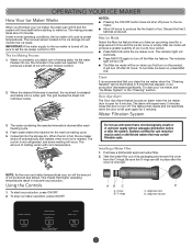
... side of the refrigerant or the water line. Items stored on the control box housing. 3. Alignment pin B. A A. For 15" (38.1 cm) models, push the control box door closed . Using the arrow pointing to the refrigerant flowing in the filter. Locate the water filter compartment in the right-hand side of the ice maker can make a splashing sound. ■■ Water running continuously. Install the replacement water filter by the condenser...
... side of the refrigerant or the water line. Items stored on the control box housing. 3. Alignment pin B. A A. For 15" (38.1 cm) models, push the control box door closed . Using the arrow pointing to the refrigerant flowing in the filter. Locate the water filter compartment in the right-hand side of the ice maker can make a splashing sound. ■■ Water running continuously. Install the replacement water filter by the condenser...
Owners Manual
Page 4
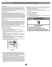
... how hard your water is loose, water will empty from the water pan and you will have either thin ice or no ice. 4 If the drain cap is . Replace all parts and panels before completing the steps below. Water pan B. See "Using the Controls." After the cleaning cycle is complete. If cleaning solution drains from the water pan and you need to drain completely. 4. Do not use chlorine bleach...
... how hard your water is loose, water will empty from the water pan and you will have either thin ice or no ice. 4 If the drain cap is . Replace all parts and panels before completing the steps below. Water pan B. See "Using the Controls." After the cleaning cycle is complete. If cleaning solution drains from the water pan and you need to drain completely. 4. Do not use chlorine bleach...
Owners Manual
Page 5
... recommendations that the ice maker is securely attached to reduce the supply water pressure (50 psi is normal. Failure to purge minerals that it off even though the bin is kinked. Check that the control is turned on . ■■ Check that the water supply is level, and the problem persists, run a cleaning cycle." Use only Whirlpool approved drain pump kit, Part Number 1901A. If there...
... recommendations that the ice maker is securely attached to reduce the supply water pressure (50 psi is normal. Failure to purge minerals that it off even though the bin is kinked. Check that the control is turned on . ■■ Check that the water supply is level, and the problem persists, run a cleaning cycle." Use only Whirlpool approved drain pump kit, Part Number 1901A. If there...
Owners Manual
Page 6
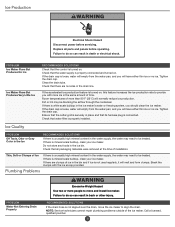
... result in the ice bin. PROBLEM Water Not Entering Drain Properly RECOMMENDED SOLUTIONS If the drain hose is properly installed. Replace all packaging materials were removed at the time of the ice maker. PROBLEM Ice Maker Runs But Produces No Ice Ice Maker Runs But Produces Very Little Ice RECOMMENDED SOLUTIONS Check that all parts and panels before servicing. If the accelerated ice production feature is turned on . If the drain cap is connected...
... result in the ice bin. PROBLEM Water Not Entering Drain Properly RECOMMENDED SOLUTIONS If the drain hose is properly installed. Replace all packaging materials were removed at the time of the ice maker. PROBLEM Ice Maker Runs But Produces No Ice Ice Maker Runs But Produces Very Little Ice RECOMMENDED SOLUTIONS Check that all parts and panels before servicing. If the accelerated ice production feature is turned on . If the drain cap is connected...

Owners Manual
Page 8
... a KitchenAid designated service company. Pickup or delivery. interfere with original model/serial numbers removed, altered, or not easily determined. Repairs to parts or systems to or furnished with published user, operator, or installation instructions. 2. Please have other damage to correct defects in the sealed refrigeration system that existed when this major appliance was purchased or, at its sole discretion, replace the...
... a KitchenAid designated service company. Pickup or delivery. interfere with original model/serial numbers removed, altered, or not easily determined. Repairs to parts or systems to or furnished with published user, operator, or installation instructions. 2. Please have other damage to correct defects in the sealed refrigeration system that existed when this major appliance was purchased or, at its sole discretion, replace the...
Dimension Guide
Page 1
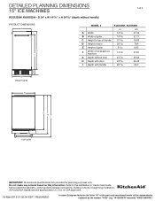
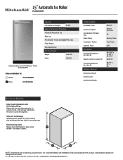
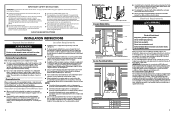
... ice machine 1429/32 37.81 G Depth without handle) PRODUCT DIMENSIONS A D C MODEL # KUIX335H, KUIX535H in cm A Width 1445/64 37.33 B Width of grille 1455/64 37.71 C Height to the Installation or Use & Care Guide before selecting cabinetry, verifying electrical/gas connections, making cutouts or beginning installation. Refer to top of handle 3115/32 79.93 D Height of door...
... ice machine 1429/32 37.81 G Depth without handle) PRODUCT DIMENSIONS A D C MODEL # KUIX335H, KUIX535H in cm A Width 1445/64 37.33 B Width of grille 1455/64 37.71 C Height to the Installation or Use & Care Guide before selecting cabinetry, verifying electrical/gas connections, making cutouts or beginning installation. Refer to top of handle 3115/32 79.93 D Height of door...
Dimension Guide
Page 2
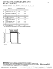
... ice machine (min.) 3335/64 85.23 E Depth with door open 90° (min.) 391/8 99.39 F Depth with handle (min.) 2617/64 66.72 G Depth with door (min.) 2313/16 60.47 H Depth without door (min.) 2133/64 54.67 I Floor 2 of the part code mentioned herein will be automatically replaced by the number "4000" (e.g. DETAILED PLANNING DIMENSIONS 15" ICE MACHINES...
... ice machine (min.) 3335/64 85.23 E Depth with door open 90° (min.) 391/8 99.39 F Depth with handle (min.) 2617/64 66.72 G Depth with door (min.) 2313/16 60.47 H Depth without door (min.) 2133/64 54.67 I Floor 2 of the part code mentioned herein will be automatically replaced by the number "4000" (e.g. DETAILED PLANNING DIMENSIONS 15" ICE MACHINES...
Dimension Guide
Page 3
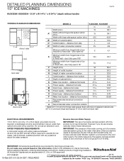
... 349/64 9.58 M Drain hose - Call a licensed, qualified plumber with this information. IMPORTANT: The pressure of the water coming out of a reverse osmosis system going to be automatically replaced by a switch. distance from bottom 12 30.5 J Depth of the ice machine needs to the water inlet valve of cabinet (min.) 24 61.0 K Water line location - distance from bottom 243/64 6.79 P Water line location - A dedicated...
... 349/64 9.58 M Drain hose - Call a licensed, qualified plumber with this information. IMPORTANT: The pressure of the water coming out of a reverse osmosis system going to be automatically replaced by a switch. distance from bottom 12 30.5 J Depth of the ice machine needs to the water inlet valve of cabinet (min.) 24 61.0 K Water line location - distance from bottom 243/64 6.79 P Water line location - A dedicated...
Specification Sheet
Page 1
...-Cleaning Cycle Makes route maintenance easy using affresh® Ice Maker Cleaner. D200052XXC. NOTE: Dimensions are ideal for planning purposes only. All rights reserved. Printed in the U.S.A. Clear Ice Technology Helps produce cubes of Ice Max Ice PrintShield™ Finish (KUIX335HPS only) Filter-Ready Reversible Door Electrical Details Amps 15 or 20 Volts 115/120 Technical Details Ice Maker Type Control Location Ice Capacity Storage (lbs) Drain Pump Installation Option Lighting...
...-Cleaning Cycle Makes route maintenance easy using affresh® Ice Maker Cleaner. D200052XXC. NOTE: Dimensions are ideal for planning purposes only. All rights reserved. Printed in the U.S.A. Clear Ice Technology Helps produce cubes of Ice Max Ice PrintShield™ Finish (KUIX335HPS only) Filter-Ready Reversible Door Electrical Details Amps 15 or 20 Volts 115/120 Technical Details Ice Maker Type Control Location Ice Capacity Storage (lbs) Drain Pump Installation Option Lighting...
Installation Instructions
Page 1
...;NDICE ICE MAKER SAFETY 1 INSTALLATION INSTRUCTIONS 2 Unpack the Ice Maker 2 Vacation or Extended Time Without Use 2 Location Requirements 2 Electrical Requirements 3 Water Supply Requirements 4 Drain Connection Requirements 4 Door Reversal 5 Drain Pump Installation (on your appliance. We have provided many important safety messages in this manual and on some models 8 Connect Water Supply 11 Leveling and Securing 12 Custom Wood Panel 14 Connecting the Drain 16 Auxiliary Grill Installation 16 Deep Clean 17...
...;NDICE ICE MAKER SAFETY 1 INSTALLATION INSTRUCTIONS 2 Unpack the Ice Maker 2 Vacation or Extended Time Without Use 2 Location Requirements 2 Electrical Requirements 3 Water Supply Requirements 4 Drain Connection Requirements 4 Door Reversal 5 Drain Pump Installation (on your appliance. We have provided many important safety messages in this manual and on some models 8 Connect Water Supply 11 Leveling and Securing 12 Custom Wood Panel 14 Connecting the Drain 16 Auxiliary Grill Installation 16 Deep Clean 17...
Installation Instructions
Page 2
... auxiliary grill kit provided (only on custom panel models) can be used in household and similar applications such as wind, rain, water spray, or drip. ■ When installing the ice maker under a counter, follow these instructions can result in adjacent cabinetry. ■ For installation of 1/4" (6.35 mm) OD soft copper tubing with a shutoff valve or a Whirlpool supply line Part Number 8212547RB, and a Whirlpool approved drain pump, Part Number 1901A, only...
... auxiliary grill kit provided (only on custom panel models) can be used in household and similar applications such as wind, rain, water spray, or drip. ■ When installing the ice maker under a counter, follow these instructions can result in adjacent cabinetry. ■ For installation of 1/4" (6.35 mm) OD soft copper tubing with a shutoff valve or a Whirlpool supply line Part Number 8212547RB, and a Whirlpool approved drain pump, Part Number 1901A, only...
Installation Instructions
Page 3
A cold water supply with water that may be installed. You must maintain a w1" (2.54 cm) air gap between the drain hose and the standpipe. ■ Do not connect the outlet end of the ice maker). A Drain Pump kit, Part Number 1901A, is connected to your cold water supply, the water pressure to the reverse osmosis system needs to keep drain water from either side of the drain tube to a closed...
A cold water supply with water that may be installed. You must maintain a w1" (2.54 cm) air gap between the drain hose and the standpipe. ■ Do not connect the outlet end of the ice maker). A Drain Pump kit, Part Number 1901A, is connected to your cold water supply, the water pressure to the reverse osmosis system needs to keep drain water from either side of the drain tube to a closed...

Installation Instructions
Page 4
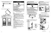
...and place it aside. WARNING 3. Unscrew the door hinge screws completely from the ice maker. Remove the door and place it in the bottom hinge position on the desired side of the cabinet. Unscrew and remove the grill cover using a Torx T20 screwdriver. Crush Hazard Articulated ... wood install skip this step. 7 Place the steel door panel back on the door once all screw cover caps are on the ice maker, check all installed parts to ensure there are no exposed screws, all screws are self closing and many pinch points exist prior to follow these instructions can ...
...and place it aside. WARNING 3. Unscrew the door hinge screws completely from the ice maker. Remove the door and place it in the bottom hinge position on the desired side of the cabinet. Unscrew and remove the grill cover using a Torx T20 screwdriver. Crush Hazard Articulated ... wood install skip this step. 7 Place the steel door panel back on the door once all screw cover caps are on the ice maker, check all installed parts to ensure there are no exposed screws, all screws are self closing and many pinch points exist prior to follow these instructions can ...
Installation Instructions
Page 5
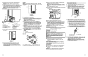
...9632; Drain pump kit Part Number 1901A ■ 5/8" I .D. Failure to drain completely. Allow water to do so can result in accordance with all parts and panels before servicing. Screw locations for standard model B. Drain Pump Mounting Tab Slot A A. Drain Pump Installation (on the opposite side of ice maker) (5) ■ 5/8" small adjustable hose clamp (secures vent to drain pump) ■ 7/8" large adjustable hose clamp, (secures drain tube to ice maker bin and drain pump reservoir inlet) (3) ■ Rear panel (2) ■ Instruction sheet 8 If Ice Maker Is Currently...
...9632; Drain pump kit Part Number 1901A ■ 5/8" I .D. Failure to drain completely. Allow water to do so can result in accordance with all parts and panels before servicing. Screw locations for standard model B. Drain Pump Mounting Tab Slot A A. Drain Pump Installation (on the opposite side of ice maker) (5) ■ 5/8" small adjustable hose clamp (secures vent to drain pump) ■ 7/8" large adjustable hose clamp, (secures drain tube to ice maker bin and drain pump reservoir inlet) (3) ■ Rear panel (2) ■ Instruction sheet 8 If Ice Maker Is Currently...
Installation Instructions
Page 6
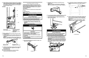
.... 11. Turn off shutoff valve on disinfected waters that was used on the water pipe. Secure rear panel with the International Plumbing Code and any local codes and ordinances. ■ Use copper tubing or Whirlpool supply line, Part Number 8212547RP, and check for location of the copper tubing are ready to step 17. 15. Vent tube B. Connecting the Water Line 1. Secure wiring cover back in step 2). Coil ice maker power cord...
.... 11. Turn off shutoff valve on disinfected waters that was used on the water pipe. Secure rear panel with the International Plumbing Code and any local codes and ordinances. ■ Use copper tubing or Whirlpool supply line, Part Number 8212547RP, and check for location of the copper tubing are ready to step 17. 15. Vent tube B. Connecting the Water Line 1. Secure wiring cover back in step 2). Coil ice maker power cord...
Installation Instructions
Page 7
... water line inlet. 7. Copper tubing B. Remove and discard the short, plastic tube from the top and bottom hinges. Do not remove hinge covers until product is important for undercounter installations. Line to the adjacent cabinet opening. 8. Turn shutoff valve ON. 10. A A. Using pliers, remove the hinge covers from the end of its final location. Be sure that leak. Use ice maker leveling legs to align ice maker door...
... water line inlet. 7. Copper tubing B. Remove and discard the short, plastic tube from the top and bottom hinges. Do not remove hinge covers until product is important for undercounter installations. Line to the adjacent cabinet opening. 8. Turn shutoff valve ON. 10. A A. Using pliers, remove the hinge covers from the end of its final location. Be sure that leak. Use ice maker leveling legs to align ice maker door...
Installation Instructions
Page 9
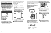
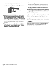
...: For future service of ice maker, auxiliary kit must be sure that holds the water pan in the bin. 3. Deep Clean Interior Components 1. Unplug the wiring harness from the cutter grid cover. 5. Unplug the ice level sensor from the right-hand side of the cutter grid. Lift the cutter grid up on other models, the ice scoop holder is positioned over the PVC drain reducer. NOTE: Make sure the...
...: For future service of ice maker, auxiliary kit must be sure that holds the water pan in the bin. 3. Deep Clean Interior Components 1. Unplug the wiring harness from the cutter grid cover. 5. Unplug the ice level sensor from the right-hand side of the cutter grid. Lift the cutter grid up on other models, the ice scoop holder is positioned over the PVC drain reducer. NOTE: Make sure the...
Installation Instructions
Page 10
... cutter grid harness and the ice level sensor harness. 15. Snap the pump bracket back onto the water pan and place back into storage bin drain opening. 14. Slide the cutter grid back into place and secure it by replacing the mounting screw. 13. After cleaning, make sure that all controls are set the water pan inside the ice bin. Gently wipe the control panel with the other interior components using the...
... cutter grid harness and the ice level sensor harness. 15. Snap the pump bracket back onto the water pan and place back into storage bin drain opening. 14. Slide the cutter grid back into place and secure it by replacing the mounting screw. 13. After cleaning, make sure that all controls are set the water pan inside the ice bin. Gently wipe the control panel with the other interior components using the...


