Use and Care Guide
Page 1
ELECTRIC RANGE ARCHITECT® SERIES II Use & Care Guide For questions about features, operation/performance, parts accessories or service, call: 1-800-422-1230 or visit our website at www.kitchenaid.com In Canada, call for assistance, installation and service, call: 1-800-807-6777 or visit our website at www.KitchenAid.ca Table of Contents...2 Models KESK901 KESS907 KERS807 KESS908 YKESS907 YKERS807 YKESS908 W10109440
ELECTRIC RANGE ARCHITECT® SERIES II Use & Care Guide For questions about features, operation/performance, parts accessories or service, call: 1-800-422-1230 or visit our website at www.kitchenaid.com In Canada, call for assistance, installation and service, call: 1-800-807-6777 or visit our website at www.KitchenAid.ca Table of Contents...2 Models KESK901 KESS907 KERS807 KESS908 YKESS907 YKERS807 YKESS908 W10109440
Use and Care Guide
Page 2
...-Activated Custom Control Temperature Management System 10 Cooktop Controls - Option 6 17 Sabbath Mode - Option 5 (on some models 29 TROUBLESHOOTING 30 ASSISTANCE OR SERVICE 31 In the U.S.A 31 In Canada 31 WARRANTY 32 2 Standard Knobs 13 GLASS TOUCH-ACTIVATED ELECTRONIC OVEN CONTROL 15...Clock/Timer Display 16 Timer 16 OPTIONS 16 Options Selection Pad 16 Fahrenheit and Celsius - TABLE OF CONTENTS RANGE SAFETY 3 The Anti-Tip Bracket 3 PARTS AND FEATURES 5 COOKTOP USE 9 Ceramic Glass 9 Cookware 9 Home Canning 10 Cooktop Controls - Options 2 , 3, 4 17 ...
...-Activated Custom Control Temperature Management System 10 Cooktop Controls - Option 6 17 Sabbath Mode - Option 5 (on some models 29 TROUBLESHOOTING 30 ASSISTANCE OR SERVICE 31 In the U.S.A 31 In Canada 31 WARRANTY 32 2 Standard Knobs 13 GLASS TOUCH-ACTIVATED ELECTRONIC OVEN CONTROL 15...Clock/Timer Display 16 Timer 16 OPTIONS 16 Options Selection Pad 16 Fahrenheit and Celsius - TABLE OF CONTENTS RANGE SAFETY 3 The Anti-Tip Bracket 3 PARTS AND FEATURES 5 COOKTOP USE 9 Ceramic Glass 9 Cookware 9 Home Canning 10 Cooktop Controls - Options 2 , 3, 4 17 ...
Use and Care Guide
Page 4
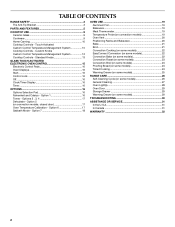
...not touch, or let clothing or other servicing should be positioned so that may penetrate the broken cooktop and create a risk of electric shock. Proper relationship of utensil to burner will expose a portion of the heating element to direct contact and may subject wiring ...of any part of the range unless specifically recommended in ignition of a range - TO CHECK IF THE DEVICES ARE INSTALLED PROPERLY, SLIDE RANGE FORWARD, LOOK FOR ANTI-TIP BRACKET SECURELY ATTACHED TO FLOOR, AND SLIDE RANGE BACK SO REAR RANGE FOOT IS UNDER ANTI-TIP BRACKET. s Never Use the Range for range-top service...
...not touch, or let clothing or other servicing should be positioned so that may penetrate the broken cooktop and create a risk of electric shock. Proper relationship of utensil to burner will expose a portion of the heating element to direct contact and may subject wiring ...of any part of the range unless specifically recommended in ignition of a range - TO CHECK IF THE DEVICES ARE INSTALLED PROPERLY, SLIDE RANGE FORWARD, LOOK FOR ANTI-TIP BRACKET SECURELY ATTACHED TO FLOOR, AND SLIDE RANGE BACK SO REAR RANGE FOOT IS UNDER ANTI-TIP BRACKET. s Never Use the Range for range-top service...

Use and Care Guide
Page 5
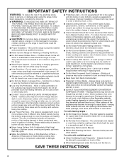
...A B. Oven display B. Left front touch control (triple-size element) I . Left rear touch control (dual-size element) G F ED C B 5 The range you have purchased may not match those of the items listed. Zone diameter indicator (single) I F. Right front touch control (single element) C. Glass Touch-Activated Electronic... TIME PROBE TEMP HR MIN COOK TIME NIGHT LIGHT DELAY MIN HR SEC MIN START TIME STOP TIME B A. PARTS AND FEATURES This manual covers several different models. Zone diameter indicator (dual) G. Increase/Decrease temperature touch control H J.
...A B. Oven display B. Left front touch control (triple-size element) I . Left rear touch control (dual-size element) G F ED C B 5 The range you have purchased may not match those of the items listed. Zone diameter indicator (single) I F. Right front touch control (single element) C. Glass Touch-Activated Electronic... TIME PROBE TEMP HR MIN COOK TIME NIGHT LIGHT DELAY MIN HR SEC MIN START TIME STOP TIME B A. PARTS AND FEATURES This manual covers several different models. Zone diameter indicator (dual) G. Increase/Decrease temperature touch control H J.
Use and Care Guide
Page 6
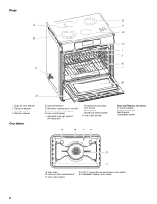
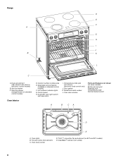
Triple-size element C. Ceramic surface cooking area H. Oven door window A B CA Parts and Features not shown (on some models) Broiler pan and grid Roasting rack Temperature probe D E A. Electronic cooktop touch controls G. Anti-tip bracket D. Dual-size element F. ... B. Model and serial number M. Dual-size oval element B. Temperature probe jack (not shown) K. T.H.E.™ convection fan and element (not visible) E. Full and center broil elements C. Range E A F G B H I .
Triple-size element C. Ceramic surface cooking area H. Oven door window A B CA Parts and Features not shown (on some models) Broiler pan and grid Roasting rack Temperature probe D E A. Electronic cooktop touch controls G. Anti-tip bracket D. Dual-size element F. ... B. Model and serial number M. Dual-size oval element B. Temperature probe jack (not shown) K. T.H.E.™ convection fan and element (not visible) E. Full and center broil elements C. Range E A F G B H I .
Use and Care Guide
Page 8
Range D E F A G H I . Temperature probe jack (not shown) (electronic knob control only) J. Oven door window Parts and Features not shown (on 807 and 907 models) E. Automatic oven light switch/ self-clean latch I J B K L C A. Model and serial number L. Oven cavity sensor D. CleanBake™ ...
Range D E F A G H I . Temperature probe jack (not shown) (electronic knob control only) J. Oven door window Parts and Features not shown (on 807 and 907 models) E. Automatic oven light switch/ self-clean latch I J B K L C A. Model and serial number L. Oven cavity sensor D. CleanBake™ ...
Use and Care Guide
Page 9
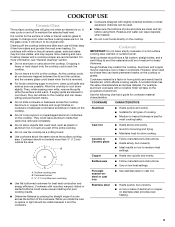
... on a hot surface cooking area, element or surface burner. Cookware material is normal for best heat conduction and energy efficiency. s Do not slide cookware or bakeware across the bottom of aluminum or copper on the cooktop. Cookware should be used . Cookware/canner C. ½" (1.3 cm)... Aluminum and copper may require more information, see "General Cleaning" section. Use the following chart as a core or base in any part of medium-to cool down , they can be removed completely. Aluminum or copper bottoms and rough finishes on low to its base material...
... on a hot surface cooking area, element or surface burner. Cookware material is normal for best heat conduction and energy efficiency. s Do not slide cookware or bakeware across the bottom of aluminum or copper on the cooktop. Cookware should be used . Cookware/canner C. ½" (1.3 cm)... Aluminum and copper may require more information, see "General Cleaning" section. Use the following chart as a core or base in any part of medium-to cool down , they can be removed completely. Aluminum or copper bottoms and rough finishes on low to its base material...
Use and Care Guide
Page 18
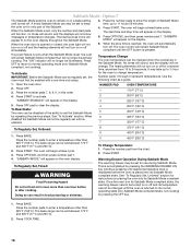
... . When the Sabbath Mode is set, only the number and start time and stop time is reached, the oven will automatically turn off for only part of the Sabbath. Press OPTIONS, and then press number pad 7. Press OFF to return to set , the oven must first be enabled with a ...Mode. enabled. 7 250°F (120°C) 300°F (149°C) 325°F (163°C) 350°F (177°C) To Regularly Set, Untimed: 1. The bake range can be actively cooking. "SABBATH MODE" will no tones will sound, and the displays will appear on or off . Press the number pads to enter...
... . When the Sabbath Mode is set, only the number and start time and stop time is reached, the oven will automatically turn off for only part of the Sabbath. Press OPTIONS, and then press number pad 7. Press OFF to return to set , the oven must first be enabled with a ...Mode. enabled. 7 250°F (120°C) 300°F (149°C) 325°F (163°C) 350°F (177°C) To Regularly Set, Untimed: 1. The bake range can be actively cooking. "SABBATH MODE" will no tones will sound, and the displays will appear on or off . Press the number pads to enter...
Use and Care Guide
Page 31
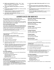
...cooking? Oven peeking releases oven heat and can also look in your nearest KitchenAid designated service center. s Are baked items too brown on "Shopping Options," then "Replacement Parts and Accessories." Use aluminum foil to higher position in Canada. ASSISTANCE OR...us or your correspondence. These factory specified parts will help , follow the menu prompts. KitchenAid® Stainless Steel Cleaner & Polish (stainless steel models) Order Part Number 4396920 KitchenAid® Stainless Steel Wipes (stainless steel models) Order Part Number 8212510 Cooktop Cleaner (porcelain or ...
...cooking? Oven peeking releases oven heat and can also look in your nearest KitchenAid designated service center. s Are baked items too brown on "Shopping Options," then "Replacement Parts and Accessories." Use aluminum foil to higher position in Canada. ASSISTANCE OR...us or your correspondence. These factory specified parts will help , follow the menu prompts. KitchenAid® Stainless Steel Cleaner & Polish (stainless steel models) Order Part Number 4396920 KitchenAid® Stainless Steel Wipes (stainless steel models) Order Part Number 8212510 Cooktop Cleaner (porcelain or ...
Use and Care Guide
Page 32
KITCHENAID® ELECTRIC RANGE WARRANTY ONE YEAR LIMITED WARRANTY For one year from the date of your appliance if it . Service must provide proof of the ceramic glass cooktop s Surface unit elements ITEMS KITCHENAID WILL NOT PAY FOR 1. Service calls to or furnished with electrical or plumbing codes, or use of KitchenAid, U.S.A., KitchenAid... maintained according to instructions attached to or furnished with the product, KitchenAid or KitchenAid Canada (hereafter "KitchenAid") will pay for factory specified parts for product service in the home. 7. Expenses for travel and ...
KITCHENAID® ELECTRIC RANGE WARRANTY ONE YEAR LIMITED WARRANTY For one year from the date of your appliance if it . Service must provide proof of the ceramic glass cooktop s Surface unit elements ITEMS KITCHENAID WILL NOT PAY FOR 1. Service calls to or furnished with electrical or plumbing codes, or use of KitchenAid, U.S.A., KitchenAid... maintained according to instructions attached to or furnished with the product, KitchenAid or KitchenAid Canada (hereafter "KitchenAid") will pay for factory specified parts for product service in the home. 7. Expenses for travel and ...
Installation Instructions
Page 2
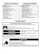
...Height 7 Adjust Leveling Legs 8 Install Anti-Tip Bracket 8 Electrical Connection - WARNING You can be killed or seriously injured if you what can result in Ranges Only 7 INSTALLATION INSTRUCTIONS 7 Unpack Range 7 Measure for Slide-in death or serious burns to follow the safety alert ... You can be killed or seriously injured if you how to rear range foot. Reconnect the anti-tip bracket, if the range is the safety alert symbol. TABLE OF CONTENTS RANGE SAFETY 2 INSTALLATION REQUIREMENTS 3 Tools and Parts 3 Location Requirements 3 Electrical Requirements -
...Height 7 Adjust Leveling Legs 8 Install Anti-Tip Bracket 8 Electrical Connection - WARNING You can be killed or seriously injured if you what can result in Ranges Only 7 INSTALLATION INSTRUCTIONS 7 Unpack Range 7 Measure for Slide-in death or serious burns to follow the safety alert ... You can be killed or seriously injured if you how to rear range foot. Reconnect the anti-tip bracket, if the range is the safety alert symbol. TABLE OF CONTENTS RANGE SAFETY 2 INSTALLATION REQUIREMENTS 3 Tools and Parts 3 Location Requirements 3 Electrical Requirements -
Installation Instructions
Page 3
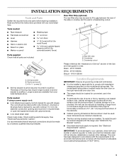
...range should be located for convenient use with nominal 1³⁄₈" (3.5 cm) diameter connection opening dimensions that all parts are shown must end in accordance with the requirements of UL and CSA International and complies with the maximum allowable wood cabinet temperatures of burns or fire by a licensed, qualified electrical...the rear of the slide-in cooktop and the wall in the kitchen. ■ To eliminate the risk of 194°F (90°C). 3 INSTALLATION REQUIREMENTS Tools and Parts Gather the required tools and parts before starting installation. ...
...range should be located for convenient use with nominal 1³⁄₈" (3.5 cm) diameter connection opening dimensions that all parts are shown must end in accordance with the requirements of UL and CSA International and complies with the maximum allowable wood cabinet temperatures of burns or fire by a licensed, qualified electrical...the rear of the slide-in cooktop and the wall in the kitchen. ■ To eliminate the risk of 194°F (90°C). 3 INSTALLATION REQUIREMENTS Tools and Parts Gather the required tools and parts before starting installation. ...
Installation Instructions
Page 4
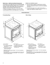
... Safety Standard, Title 24 CFR, Part 3280 (formerly the Federal Standard for Manufactured Home Installations, ANSI A225.1/NFPA 501A or follow local codes. Mobile home installations require: ■ When this range is installed in * C. Product Dimensions Freestanding Range Slide-in Range B A F** D* C G E A F E** B* C D A. 5³⁄₄" (14.6 cm) B. 30" (76.2 cm) C. 41&#... countertop; In Canada, the installation of oven door protrudes 1³⁄₄" (4.4 cm) beyond 24" (61 cm) base cabinet. See "Electrical Connection" section. front of this range must be revised.
... Safety Standard, Title 24 CFR, Part 3280 (formerly the Federal Standard for Manufactured Home Installations, ANSI A225.1/NFPA 501A or follow local codes. Mobile home installations require: ■ When this range is installed in * C. Product Dimensions Freestanding Range Slide-in Range B A F** D* C G E A F E** B* C D A. 5³⁄₄" (14.6 cm) B. 30" (76.2 cm) C. 41&#... countertop; In Canada, the installation of oven door protrudes 1³⁄₄" (4.4 cm) beyond 24" (61 cm) base cabinet. See "Electrical Connection" section. front of this range must be revised.

Installation Instructions
Page 6
... conform with upturned ends, terminating in death, fire, or electrical shock. or 50-amp range power supply cord (pigtail). Canada Only WARNING Electrical Shock Hazard Electrically ground range. ■ This range is manufactured with the ground connected to the cabinet. When ...Electrical Connection." ■ Allow 2 to 3 ft (61.0 cm to do not permit ground through flexible or nonmetallic sheathed, copper or aluminum cable. Failure to 91.4 cm) of slack in conformance with a UL listed strain relief and be Type SRD or SRDT with CSA Standard C22.1, Canadian Electrical Code, Part...
... conform with upturned ends, terminating in death, fire, or electrical shock. or 50-amp range power supply cord (pigtail). Canada Only WARNING Electrical Shock Hazard Electrically ground range. ■ This range is manufactured with the ground connected to the cabinet. When ...Electrical Connection." ■ Allow 2 to 3 ft (61.0 cm to do not permit ground through flexible or nonmetallic sheathed, copper or aluminum cable. Failure to 91.4 cm) of slack in conformance with a UL listed strain relief and be Type SRD or SRDT with CSA Standard C22.1, Canadian Electrical Code, Part...
Installation Instructions
Page 7
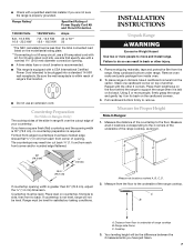
.... If you have just taken. 7 C B A A. Countertop Preparation (for Slide-in Ranges Only) The cooktop sides of the slide-in back or other 2 corners. Using 2 or more people to support the range when it on its back on its back. Remove shipping materials, tape and protective...firmly grasp the range and gently lay it is less than 30" (76.2 cm), adjust the ³⁄₈" (1.0 cm) dimension. Pull cardboard bottom firmly to underside of your countertop. ■ Check with a qualified electrical installer if you are not sure the range is required. Range Rating* 120/...
.... If you have just taken. 7 C B A A. Countertop Preparation (for Slide-in Ranges Only) The cooktop sides of the slide-in back or other 2 corners. Using 2 or more people to support the range when it on its back on its back. Remove shipping materials, tape and protective...firmly grasp the range and gently lay it is less than 30" (76.2 cm), adjust the ³⁄₈" (1.0 cm) dimension. Pull cardboard bottom firmly to underside of your countertop. ■ Check with a qualified electrical installer if you are not sure the range is required. Range Rating* 120/...
Installation Instructions
Page 13
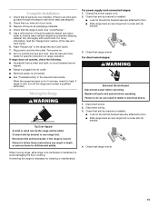
...: ■ Look for the anti-tip bracket securely attached to floor. ■ Slide range back so rear range foot is under anti-tip bracket. 3. Check that range is an extra part, go back through the steps to follow these instructions can result in the Use and... check for specific instruction on range operation. Failure to see which step was skipped. 2. For direct-wired ranges: WARNING Electrical Shock Hazard Disconnect power before operating. Disconnect wiring. 3. Reconnect the anti-tip bracket, if the range is level. Check that the range is moved. Failure to avoid...
...: ■ Look for the anti-tip bracket securely attached to floor. ■ Slide range back so rear range foot is under anti-tip bracket. 3. Check that range is an extra part, go back through the steps to follow these instructions can result in the Use and... check for specific instruction on range operation. Failure to see which step was skipped. 2. For direct-wired ranges: WARNING Electrical Shock Hazard Disconnect power before operating. Disconnect wiring. 3. Reconnect the anti-tip bracket, if the range is level. Check that the range is moved. Failure to avoid...
Parts Diagram
Page 1
... Models: KESK901SBL00, KESK901SWH00, KESK901SSS00 (Black) (Pure White) (S.Steel) 30" Slide−In ELECTRIC OVEN Illus. No. Part No. Part No. Lamp 18 3196160 Screw (2) 19 9759094 Spring, Locator 20 9761768 Bracket, Rear Sprt 21 9763517 Rail, Element (2) ... Grommet (19mm) 29 W10050280 Grommet (38mm) 11−06 Litho in U.S.A. (cre) 1 Part No. 8186660 DESCRIPTION 16 9759944 Thrmstat, 60c SPST 17 9758799 Bracket, Ind. DESCRIPTION 1 Literaturre Parts 9763461 Installation Instructiions W10109440 Use & Care Guide 9762785 Tech Sheet 9757680 Anti−Tip Instruct. 3191638...
... Models: KESK901SBL00, KESK901SWH00, KESK901SSS00 (Black) (Pure White) (S.Steel) 30" Slide−In ELECTRIC OVEN Illus. No. Part No. Part No. Lamp 18 3196160 Screw (2) 19 9759094 Spring, Locator 20 9761768 Bracket, Rear Sprt 21 9763517 Rail, Element (2) ... Grommet (19mm) 29 W10050280 Grommet (38mm) 11−06 Litho in U.S.A. (cre) 1 Part No. 8186660 DESCRIPTION 16 9759944 Thrmstat, 60c SPST 17 9758799 Bracket, Ind. DESCRIPTION 1 Literaturre Parts 9763461 Installation Instructiions W10109440 Use & Care Guide 9762785 Tech Sheet 9757680 Anti−Tip Instruct. 3191638...
Parts Diagram
Page 2
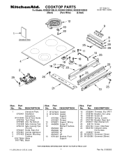
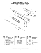
..., Infinite 4456027 LF 4454539 LR 4454540 RF 4454541 RR 12 9757778 Bushing 13 Switch, Accusimmer 9761781BL Black 9761781WH White 14 3196537 Screw 2 8186660 CONTROL PANEL PARTS For Models: KESK901SBL00, KESK901SWH00, KESK901SSS00 (Black) (Pure White) (S.Steel) Illus. DESCRIPTION 1 Control Panel 9761645WH White 9761645BL Black 9761645NP S.Steel 2 9761565 Switch, Membrane ...No. DESCRIPTION 9 Knob (LF) 9762763WH White 9762763BL Black 9762763NP S.Steel (RF,RR,LR) 9761570WH White 9761570BL Black 9761570NP S.Steel Illus. No. No. Part No. Part No. Part No.
..., Infinite 4456027 LF 4454539 LR 4454540 RF 4454541 RR 12 9757778 Bushing 13 Switch, Accusimmer 9761781BL Black 9761781WH White 14 3196537 Screw 2 8186660 CONTROL PANEL PARTS For Models: KESK901SBL00, KESK901SWH00, KESK901SSS00 (Black) (Pure White) (S.Steel) Illus. DESCRIPTION 1 Control Panel 9761645WH White 9761645BL Black 9761645NP S.Steel 2 9761565 Switch, Membrane ...No. DESCRIPTION 9 Knob (LF) 9762763WH White 9762763BL Black 9762763NP S.Steel (RF,RR,LR) 9761570WH White 9761570BL Black 9761570NP S.Steel Illus. No. No. Part No. Part No. Part No.
Parts Diagram
Page 3
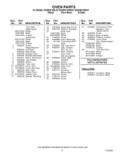
OVEN PARTS For Models: KESK901SBL00, KESK901SWH00, KESK901SSS00 (Black) (Pure White) (S.Steel) 8186660 3
OVEN PARTS For Models: KESK901SBL00, KESK901SWH00, KESK901SSS00 (Black) (Pure White) (S.Steel) 8186660 3
Parts Diagram
Page 4
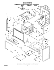
... S.Steel 55 Trim, Btm Vent W10104910 White W10104890 Black W10104870 S.Steel FOLLOWING PARTS NOT ILLUSTRATED INSULATION 9756817 Insulation, Wrap 9756470 Insulation, Back 4 8186660 No. No. Part No. No. DESCRIPTION 18 9757685 Guide,Side Pnl (2) 19 4451478 Support, ... & L.H.) 26 9759761 Back, Chassis 27 Liner, Oven (Not serviceable) 28 9759945 Cover, Rear Standoff 29 4455636 Sensor 30 9756454 Bracket, GOC 31 W10083460 Slide. DESCRIPTION 1 Trim, Side (Right Hand) 9761572WH White 9761572BL Black 9761572SS S.Steel (Left Hand) 9761571WH White 9761571BL Black ...
... S.Steel 55 Trim, Btm Vent W10104910 White W10104890 Black W10104870 S.Steel FOLLOWING PARTS NOT ILLUSTRATED INSULATION 9756817 Insulation, Wrap 9756470 Insulation, Back 4 8186660 No. No. Part No. No. DESCRIPTION 18 9757685 Guide,Side Pnl (2) 19 4451478 Support, ... & L.H.) 26 9759761 Back, Chassis 27 Liner, Oven (Not serviceable) 28 9759945 Cover, Rear Standoff 29 4455636 Sensor 30 9756454 Bracket, GOC 31 W10083460 Slide. DESCRIPTION 1 Trim, Side (Right Hand) 9761572WH White 9761572BL Black 9761572SS S.Steel (Left Hand) 9761571WH White 9761571BL Black ...


