

User Manual
Page 3
... discs and tapes 5 System connection (XD-7...series 6 Connection of the System Accessories 6 Connection of Options (Optional Parts 8 System connection (XD-5...series 10 Connection of the System Accessories 10 Connection of Options (Optional Parts 12 Controls and indicators 14 Main Unit 14 Display 16 Remote control Unit 17 Operation of remote control unit 18 CHANNEL SPACE setting 18 Basic section Let's put out some sound 20 Basic use method 20 Playback of CD 22 Playback of tape 24 Searching for the desired music program...
... discs and tapes 5 System connection (XD-7...series 6 Connection of the System Accessories 6 Connection of Options (Optional Parts 8 System connection (XD-5...series 10 Connection of the System Accessories 10 Connection of Options (Optional Parts 12 Controls and indicators 14 Main Unit 14 Display 16 Remote control Unit 17 Operation of remote control unit 18 CHANNEL SPACE setting 18 Basic section Let's put out some sound 20 Basic use method 20 Playback of CD 22 Playback of tape 24 Searching for the desired music program...

User Manual
Page 4
... to recreate a sound field. Built in sub woofer (XD-7....series only) ¡ Each 3-way speaker incorporates an additional sub woofer to you transport or ship the unit in again during demonstration to operate, notify your unit was shipped to reproduce heavy bass more powerfully than conventional system speakers. 3-Disc carousel CD player ™ Three discs can be set. It is also available on the remote control unit. If...
... to recreate a sound field. Built in sub woofer (XD-7....series only) ¡ Each 3-way speaker incorporates an additional sub woofer to you transport or ship the unit in again during demonstration to operate, notify your unit was shipped to reproduce heavy bass more powerfully than conventional system speakers. 3-Disc carousel CD player ™ Three discs can be set. It is also available on the remote control unit. If...
User Manual
Page 5
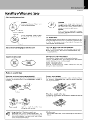
... Handling of time, remove it from the CD player and store it in its case. CD accessories The CD accessories (stabilizer, protection sheet, protection ring, etc.) which are marketed for a long period of discs and tapes Disc handling precautions 5 Before applying power XD-SERIES (En) Handling Hold compact discs so that you do not touch the playing surface. Therefore, to avoid malfunction, never use cleaning discs. Basic...
... Handling of time, remove it from the CD player and store it in its case. CD accessories The CD accessories (stabilizer, protection sheet, protection ring, etc.) which are marketed for a long period of discs and tapes Disc handling precautions 5 Before applying power XD-SERIES (En) Handling Hold compact discs so that you do not touch the playing surface. Therefore, to avoid malfunction, never use cleaning discs. Basic...

User Manual
Page 6
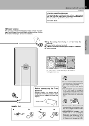
... difficulty". properly, reset the microcomputer referring to a direction which provides the best reception. AM loop antenna P The supplied antenna is for system and accessories. possible from the main system, TV set, speaker cords and power cord, and set it as far as Europe and U.K. FM 75Ω Other countries ANTENNA AM GND FM 75Ω 2 GND FM 300Ω AM XD-SERIES (En) Speaker (right) −+ L ANTENNA R AUX OUTPUT L R AUX INPUT AUX INPUT LEVEL FM...
... difficulty". properly, reset the microcomputer referring to a direction which provides the best reception. AM loop antenna P The supplied antenna is for system and accessories. possible from the main system, TV set, speaker cords and power cord, and set it as far as Europe and U.K. FM 75Ω Other countries ANTENNA AM GND FM 75Ω 2 GND FM 300Ω AM XD-SERIES (En) Speaker (right) −+ L ANTENNA R AUX OUTPUT L R AUX INPUT AUX INPUT LEVEL FM...

User Manual
Page 7
... connection cords are imper- Speaker and TV installation If there is a magnet or other device generating magnetic force nearby, interaction between the magnet and speaker may result. If this happens, move the speaker at least 20 cm away from slipping. For stable signal reception we recommend using an outdoor antenna. In case an associated system component is connected, also read the instruction manual of musical...
... connection cords are imper- Speaker and TV installation If there is a magnet or other device generating magnetic force nearby, interaction between the magnet and speaker may result. If this happens, move the speaker at least 20 cm away from slipping. For stable signal reception we recommend using an outdoor antenna. In case an associated system component is connected, also read the instruction manual of musical...

User Manual
Page 8
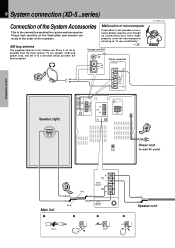
...DIGITAL OUT jack (OPTICAL) If necessary, remove the cap and plug the optical-fiber cable (optional). R + SUB WOOFER SPEAKERS (12-16Ω) + L - - System connection (XD-7...series) XD-SERIES (En) In regard to the SURROUND switch This switch can be used only when the separately sold parts as shown in the figure. R + FRONT SPEAKERS (6-16Ω) % ON SURROUND fi OFF -+ L R SURROUND SPEAKERS (8-16Ω) MIN. Audio output MD recorder Audio input 1 2 Surround (rear) speakers R L 3 −+ −+ L R AUX OUTPUT L R AUX INPUT AUX INPUT LEVEL L ANTENNA R AUX...
...DIGITAL OUT jack (OPTICAL) If necessary, remove the cap and plug the optical-fiber cable (optional). R + SUB WOOFER SPEAKERS (12-16Ω) + L - - System connection (XD-7...series) XD-SERIES (En) In regard to the SURROUND switch This switch can be used only when the separately sold parts as shown in the figure. R + FRONT SPEAKERS (6-16Ω) % ON SURROUND fi OFF -+ L R SURROUND SPEAKERS (8-16Ω) MIN. Audio output MD recorder Audio input 1 2 Surround (rear) speakers R L 3 −+ −+ L R AUX OUTPUT L R AUX INPUT AUX INPUT LEVEL L ANTENNA R AUX...
User Manual
Page 10
.... properly, reset the microcomputer referring to a direction which provides the best reception. AM loop antenna P The supplied antenna is the connection method for indoor use. MAX. + L - FRONT SPEAKERS (6-16Ω) - R + SUPER WOOFER PRE OUT % ON SURROUND fi OFF -+ L R SURROUND SPEAKERS (6-16Ω) DIGITAL OUT OPTICAL 4 Power cord To wall AC outlet Application section Knowledge sections 3 Red Main Unit 1 Black 2 + L - possible from the main system, TV set, speaker cords and power cord, and set it...
.... properly, reset the microcomputer referring to a direction which provides the best reception. AM loop antenna P The supplied antenna is the connection method for indoor use. MAX. + L - FRONT SPEAKERS (6-16Ω) - R + SUPER WOOFER PRE OUT % ON SURROUND fi OFF -+ L R SURROUND SPEAKERS (6-16Ω) DIGITAL OUT OPTICAL 4 Power cord To wall AC outlet Application section Knowledge sections 3 Red Main Unit 1 Black 2 + L - possible from the main system, TV set, speaker cords and power cord, and set it...
User Manual
Page 11
rear panel: 10 cm FM indoor antenna The accessory antenna is connected, also read the instruction manual of musical instruments, etc. If the left plugged in, malfunction or damage may interfere. 2. If their connections are imper- 4 fect, the sound may not be produced or noise may result. plugged with unclear positioning of the component. 2. Preparation section Basic section Application section Speaker (left) BASS REFLEX SPEAKER SYSTEM BASS REFLEX SPEAKER SYSTEM −...
rear panel: 10 cm FM indoor antenna The accessory antenna is connected, also read the instruction manual of musical instruments, etc. If the left plugged in, malfunction or damage may interfere. 2. If their connections are imper- 4 fect, the sound may not be produced or noise may result. plugged with unclear positioning of the component. 2. Preparation section Basic section Application section Speaker (left) BASS REFLEX SPEAKER SYSTEM BASS REFLEX SPEAKER SYSTEM −...

User Manual
Page 12
... -+ L R SURROUND SPEAKERS (8-16Ω) Optical-fiber cable DIGITAL OUT OPTICAL (Provided with any type of the required connections have been made. When the switch is played back powerfully. Preparation section Audio output MD recorder Audio input 1 2 Surround (rear) speakers R L 3 −+ −+ Basic section L R AUX OUTPUT L R AUX INPUT AUX INPUT LEVEL L ANTENNA R AUX OUTPUT L R AUX INPUT AUX INPUT LEVEL FM 75Ω GND FM 300Ω AM MIN. R + SUPER WOOFER PRE OUT MIN. This can be used only when the separately sold parts...
... -+ L R SURROUND SPEAKERS (8-16Ω) Optical-fiber cable DIGITAL OUT OPTICAL (Provided with any type of the required connections have been made. When the switch is played back powerfully. Preparation section Audio output MD recorder Audio input 1 2 Surround (rear) speakers R L 3 −+ −+ Basic section L R AUX OUTPUT L R AUX INPUT AUX INPUT LEVEL L ANTENNA R AUX OUTPUT L R AUX INPUT AUX INPUT LEVEL FM 75Ω GND FM 300Ω AM MIN. R + SUPER WOOFER PRE OUT MIN. This can be used only when the separately sold parts...

User Manual
Page 14
... Main Unit XD-SERIES (En) Preparation section POWER (For U.S.A. MIC -2 INPUT MIC VOL. BASS DISPLAY TIMER MODE /DEMO 1- MIN MAX SOUND SET 0 PUSH OPEN DOWN MULTI CONTROL SRS 3D CD PGM DUBBING ENTER TUNING BAND AUTO PHONES 0 PUSH OPEN PLAY REC /PLAY DISC 1 REV.MODE DOLBY NR 1 2 7 DISC 2 DISC SKIP DISC 3 REC/ARM 3 ¡ A/B 0 4¢ 76 & * ( Basic section Application section Knowledge sections and Canada) 7 890 ! @ # $%^ 1 2 3 4 5 6 ) ¡ ™ ¶ • ª MINI HiFi COMPONENT SYSTEM SRS ( ) UP VOLUME CONTROL ON/STANDBY EX.
... Main Unit XD-SERIES (En) Preparation section POWER (For U.S.A. MIC -2 INPUT MIC VOL. BASS DISPLAY TIMER MODE /DEMO 1- MIN MAX SOUND SET 0 PUSH OPEN DOWN MULTI CONTROL SRS 3D CD PGM DUBBING ENTER TUNING BAND AUTO PHONES 0 PUSH OPEN PLAY REC /PLAY DISC 1 REV.MODE DOLBY NR 1 2 7 DISC 2 DISC SKIP DISC 3 REC/ARM 3 ¡ A/B 0 4¢ 76 & * ( Basic section Application section Knowledge sections and Canada) 7 890 ! @ # $%^ 1 2 3 4 5 6 ) ¡ ™ ¶ • ª MINI HiFi COMPONENT SYSTEM SRS ( ) UP VOLUME CONTROL ON/STANDBY EX.

User Manual
Page 15
... a tape. ¡ DOLBY NR key ∞ Dolby noise reduction ON/OFF switching is used for insertion of a CD to the status at that a tape or disc has already been loaded. 5 MIC 1, MIC 2 terminal (Except for the equalizer mode setting, etc. 15 Controls and indicators XD-SERIES (En) ! AUTO key Switches the tuning mode. (PHONES terminal ) For connection of AM broadcasting. §REC/ARM key ⁄‹ Press to start recording. Used...
... a tape. ¡ DOLBY NR key ∞ Dolby noise reduction ON/OFF switching is used for insertion of a CD to the status at that a tape or disc has already been loaded. 5 MIC 1, MIC 2 terminal (Except for the equalizer mode setting, etc. 15 Controls and indicators XD-SERIES (En) ! AUTO key Switches the tuning mode. (PHONES terminal ) For connection of AM broadcasting. §REC/ARM key ⁄‹ Press to start recording. Used...

User Manual
Page 16
... disc number being played. 8Track number indicator Indicates the CD track number being played. 9Spectrum analyzer display 0RUNNING INDICATOR This indicator rotates according to the operation modes during operation of the tuner operations and applied CD operations. 3 Character information display Displays the input selection, frequency, volume level, etc. 4 Tone and sound field-related indicators 5 Timer-related indicators 6Cassette deck indicators This section contains the cassette deck operation indicators. STEREO 0 ECHO 1 2 3 NR O.T.T. Guideline Blinks during volume control...
... disc number being played. 8Track number indicator Indicates the CD track number being played. 9Spectrum analyzer display 0RUNNING INDICATOR This indicator rotates according to the operation modes during operation of the tuner operations and applied CD operations. 3 Character information display Displays the input selection, frequency, volume level, etc. 4 Tone and sound field-related indicators 5 Timer-related indicators 6Cassette deck indicators This section contains the cassette deck operation indicators. STEREO 0 ECHO 1 2 3 NR O.T.T. Guideline Blinks during volume control...
User Manual
Page 17
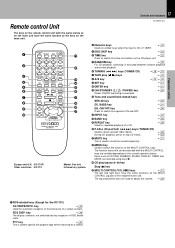
... key Used for a station. RDS DISP. Infrared ray system. 17 Controls and indicators XD-SERIES (En) Preparation section 2Numeric keys Used as the MULTI CONTROL jog dial on the amplifier/tuner unit. Items such as CD PGM, DUBBING, SOUND, DISPLAY, TIMER and MODE are selected using keys ). ( CD play (2 3) keys ¢ 8A/B key ¢¤ 9SET key ¡ 0ENTER key ¡ !ON/STANDBY ( POWER) key ) Power ON/OFF switching is CD or TUNER. £...
... key Used for a station. RDS DISP. Infrared ray system. 17 Controls and indicators XD-SERIES (En) Preparation section 2Numeric keys Used as the MULTI CONTROL jog dial on the amplifier/tuner unit. Items such as CD PGM, DUBBING, SOUND, DISPLAY, TIMER and MODE are selected using keys ). ( CD play (2 3) keys ¢ 8A/B key ¢¤ 9SET key ¡ 0ENTER key ¡ !ON/STANDBY ( POWER) key ) Power ON/OFF switching is CD or TUNER. £...

User Manual
Page 20
... switched OFF. (DIMMER function) 2. Volume adjustment DOWN 3 ÷ Quick turning produces a larger change amount. (AI VOLUME control function) ÷ The display shows a reference value. Application section Knowledge sections 20 Let's put out some sound Basic use method XD-SERIES (En) Preparation section Basic section Bass and treble compensation TIMER, MODE/DEMO 1 3 EX.BASS 2 Muting the sound temporarily SET ENTER Listening through headphones Insert the headphone plug into deck B. 3. Selecting the desired output TUNER (Radio) CD TAPE AUX...
... switched OFF. (DIMMER function) 2. Volume adjustment DOWN 3 ÷ Quick turning produces a larger change amount. (AI VOLUME control function) ÷ The display shows a reference value. Application section Knowledge sections 20 Let's put out some sound Basic use method XD-SERIES (En) Preparation section Basic section Bass and treble compensation TIMER, MODE/DEMO 1 3 EX.BASS 2 Muting the sound temporarily SET ENTER Listening through headphones Insert the headphone plug into deck B. 3. Selecting the desired output TUNER (Radio) CD TAPE AUX...

User Manual
Page 21
... ON/STANDBY ( ) switch When the display shows the time or a small amount of music and your liking. 1 Press the MODE/DEMO key. MULTI CONTROL AUTOTPOW ER | Scrolled display (AUTO POWER SAVE) ON ..... RETURN ÷ This function is not available when the AUX input is switched off automatically during recording. 21 Let's put out some sound Sub woofer level adjustment (Except for 30 minutes or more, the power is used . BASS...
... ON/STANDBY ( ) switch When the display shows the time or a small amount of music and your liking. 1 Press the MODE/DEMO key. MULTI CONTROL AUTOTPOW ER | Scrolled display (AUTO POWER SAVE) ON ..... RETURN ÷ This function is not available when the AUX input is switched off automatically during recording. 21 Let's put out some sound Sub woofer level adjustment (Except for 30 minutes or more, the power is used . BASS...

User Manual
Page 49
... (video deck etc.) connected to the desired atmosphere. Please adjust as required when the volume from external equipment is too high etc. ÷ Sound is decreased. 2 Press the ENTER key. Press SET. MULTI CONTROL SET 3 Adjust. 1 Adjust. MULTI CONTROL The right volume is not output at the MIN. ENTER The left and right volume. Indicates the center L--y--R Indicates the balance setting Input level adjustment : Rear panel L ANTENNA FM R AUX 75Ω OUTPUT L R AUX INPUT AUX INPUT LEVEL...
... (video deck etc.) connected to the desired atmosphere. Please adjust as required when the volume from external equipment is too high etc. ÷ Sound is decreased. 2 Press the ENTER key. Press SET. MULTI CONTROL SET 3 Adjust. 1 Adjust. MULTI CONTROL The right volume is not output at the MIN. ENTER The left and right volume. Indicates the center L--y--R Indicates the balance setting Input level adjustment : Rear panel L ANTENNA FM R AUX 75Ω OUTPUT L R AUX INPUT AUX INPUT LEVEL...

User Manual
Page 56
... speakers do not overlap. PROG. Timer operation XD-SERIES (En) Timer programming Two 24-hour timer systems (PROG.1, PROG.2) (which can be set and selected to tape The station should be restarted.) 1 Make preparations for record- A ÷ Playing the auxiliary input source Make timer setting of timer playback. 2 Adjust the listening volume. MULTI CONTROL SET SLEEP TIME SET O.T.T. 56 Adjust the clock before setting the timer. ÷ If you made a mistake during timer setting: Select "RETURN" in 1 and 2, enter the figure of "minute" using...
... speakers do not overlap. PROG. Timer operation XD-SERIES (En) Timer programming Two 24-hour timer systems (PROG.1, PROG.2) (which can be set and selected to tape The station should be restarted.) 1 Make preparations for record- A ÷ Playing the auxiliary input source Make timer setting of timer playback. 2 Adjust the listening volume. MULTI CONTROL SET SLEEP TIME SET O.T.T. 56 Adjust the clock before setting the timer. ÷ If you made a mistake during timer setting: Select "RETURN" in 1 and 2, enter the figure of "minute" using...

User Manual
Page 57
Timer operation XD-SERIES (En) ÷ After entering the figure of "minute" using the same procedure. creasing volume SET RETURN Enter it . 2 Select the input source. Select the preset station No. MULTI CONTROL 15 FM 89 O0 PROG.1 ENTER Enter it . SLEEP | Scrolled display (PROG. SET 2 AM8 O0 PROG.1 Preparation section 7 Make the desired reservation. MULTI CONTROL ENTER TUNER (Radio) CD TAPE AUX (External input) RETURN TUNER Enter it . ÷ If you selected TUNER, press...
Timer operation XD-SERIES (En) ÷ After entering the figure of "minute" using the same procedure. creasing volume SET RETURN Enter it . 2 Select the input source. Select the preset station No. MULTI CONTROL 15 FM 89 O0 PROG.1 ENTER Enter it . SLEEP | Scrolled display (PROG. SET 2 AM8 O0 PROG.1 Preparation section 7 Make the desired reservation. MULTI CONTROL ENTER TUNER (Radio) CD TAPE AUX (External input) RETURN TUNER Enter it . ÷ If you selected TUNER, press...

User Manual
Page 59
...) Input selection Volume control value Equalizer's manual memory created by the user SRS 3D level Tuner unit Receiving band Frequency Preset stations Program timer setting contents Cassette deck unit Transport direction DOLBY NR Reverse mode Knowledge sections When your unit needs to your dealer. Purchase of the set (Speakers excluded) to be repaired, bring the entire set When the front panel or case becomes dirty, wipe with the SOUND RETRIEVAL SYSTEM. To...
...) Input selection Volume control value Equalizer's manual memory created by the user SRS 3D level Tuner unit Receiving band Frequency Preset stations Program timer setting contents Cassette deck unit Transport direction DOLBY NR Reverse mode Knowledge sections When your unit needs to your dealer. Purchase of the set (Speakers excluded) to be repaired, bring the entire set When the front panel or case becomes dirty, wipe with the SOUND RETRIEVAL SYSTEM. To...

User Manual
Page 60
...; Replace with new batteries. * ÷ Operate the unit inside the remote control- * lable range. ÷ Set a tape or CD in the TUNER mode. ÷ Sound is not output when the radio wave is set up. ÷ Adjust the present time referring to "Clock R adjustment". ÷ Set the timer ON time and OFF time. panel is ÷ Switch the demonstration off. not produced. ÷ Turn the power OFF, remove the shortcircuit and turn the power ON again. Y ÷ Execute the timer program...
...; Replace with new batteries. * ÷ Operate the unit inside the remote control- * lable range. ÷ Set a tape or CD in the TUNER mode. ÷ Sound is not output when the radio wave is set up. ÷ Adjust the present time referring to "Clock R adjustment". ÷ Set the timer ON time and OFF time. panel is ÷ Switch the demonstration off. not produced. ÷ Turn the power OFF, remove the shortcircuit and turn the power ON again. Y ÷ Execute the timer program...


