
User Manual
Page 2
... this KENWOOD FM transceiver. MODELS COVERED BY THIS MANUAL The models listed below are grateful you decided to satisfy the requirement for 1200 bps or 9600 bps Packet operation. • A data transfer band is selectable separately from the main unit and can be assigned desired names. • "Visual Scan" graphically and simultaneously shows the conditions of up to 147 frequency channels. •...
... this KENWOOD FM transceiver. MODELS COVERED BY THIS MANUAL The models listed below are grateful you decided to satisfy the requirement for 1200 bps or 9600 bps Packet operation. • A data transfer band is selectable separately from the main unit and can be assigned desired names. • "Visual Scan" graphically and simultaneously shows the conditions of up to 147 frequency channels. •...
User Manual
Page 3
..., turn OFF the transceiver and just wait for a while. Contact a KENWOOD service station or your transceiver while driving because it is simply too dangerous. • Be aware of local laws pertaining to the use a 24 V battery to power the transceiver. If this manual or by this equipment does cause harmful interference to radio or television reception, which can generate radio frequency...
..., turn OFF the transceiver and just wait for a while. Contact a KENWOOD service station or your transceiver while driving because it is simply too dangerous. • Be aware of local laws pertaining to the use a 24 V battery to power the transceiver. If this manual or by this equipment does cause harmful interference to radio or television reception, which can generate radio frequency...
User Manual
Page 4
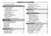
...Fixed Station Operation 4 Replacing Fuses 5 ANTENNA CONNECTION 5 ACCESSORY CONNECTIONS 6 External Speakers 6 Microphone 6 PACKET EQUIPMENT CONNECTIONS 6 2 YOUR FIRST QSO 3 GETTING ACQUAINTED BASIC TRANSCEIVER MODES 8 BUTTON FUNCTION DISPLAY 9 FRONT PANEL 10 REAR PANEL 12 MICROPHONE 13 INDICATORS 14 TRANSCEIVER GUIDE 15 4 OPERATING BASICS SWITCHING POWER ON/OFF 16 ADJUSTING VOLUME 16 ADJUSTING SQUELCH 16 SELECTING A BAND 16 ii SELECTING FREQUENCIES 17 Tuning Control 17 Microphone [UP]/[DWN] Buttons 17 TRANSMITTING 18 Selecting Output Power 18 5 MENU SET-UP WHAT IS A MENU...
...Fixed Station Operation 4 Replacing Fuses 5 ANTENNA CONNECTION 5 ACCESSORY CONNECTIONS 6 External Speakers 6 Microphone 6 PACKET EQUIPMENT CONNECTIONS 6 2 YOUR FIRST QSO 3 GETTING ACQUAINTED BASIC TRANSCEIVER MODES 8 BUTTON FUNCTION DISPLAY 9 FRONT PANEL 10 REAR PANEL 12 MICROPHONE 13 INDICATORS 14 TRANSCEIVER GUIDE 15 4 OPERATING BASICS SWITCHING POWER ON/OFF 16 ADJUSTING VOLUME 16 ADJUSTING SQUELCH 16 SELECTING A BAND 16 ii SELECTING FREQUENCIES 17 Tuning Control 17 Microphone [UP]/[DWN] Buttons 17 TRANSMITTING 18 Selecting Output Power 18 5 MENU SET-UP WHAT IS A MENU...

User Manual
Page 6
... Lock 67 S-METER SQUELCH 68 Squelch Hang Time 68 POWER-ON MESSAGE 69 DISPLAY DEMONSTRATION MODE 69 CHANGING DISPLAY CONDITIONS 70 Display Dimmer 70 Auto Dimmer Change 70 Display Contrast 71 Positive/Negative Reversal 71 CONFIGURING PROGRAM FUNCTION KEYS ...... 72 KEYPAD DIRECT ENTRY 74 Operating Frequency Entry 74 Memory Channel Number Entry 75 Tone Frequency Number Entry 75 CHANGING SPEAKER CONFIGURATIONS 76 15 MICROPHONE CONTROL ACTIVATING MICROPHONE CONTROL 78 16 PACKET OPERATION ACTIVATING DATA TX/RX BAND 79 1200/ 9600 bps OPERATION 79 DATA Connector Pin...
... Lock 67 S-METER SQUELCH 68 Squelch Hang Time 68 POWER-ON MESSAGE 69 DISPLAY DEMONSTRATION MODE 69 CHANGING DISPLAY CONDITIONS 70 Display Dimmer 70 Auto Dimmer Change 70 Display Contrast 71 Positive/Negative Reversal 71 CONFIGURING PROGRAM FUNCTION KEYS ...... 72 KEYPAD DIRECT ENTRY 74 Operating Frequency Entry 74 Memory Channel Number Entry 75 Tone Frequency Number Entry 75 CHANGING SPEAKER CONFIGURATIONS 76 15 MICROPHONE CONTROL ACTIVATING MICROPHONE CONTROL 78 16 PACKET OPERATION ACTIVATING DATA TX/RX BAND 79 1200/ 9600 bps OPERATION 79 DATA Connector Pin...

User Manual
Page 11
...; ALL FIXED STATIONS SHOULD BE EQUIPPED WITH A LIGHTNING ARRESTER TO REDUCE THE RISK OF FIRE, 14 ELECTRIC SHOCK, AND TRANSCEIVER DAMAGE. 15 Antenna 16 connector 17 18 To antenna Feed line connector 19 20 21 5 Fuse Location Fuse Current Rating Transceiver Supplied Accessory DC Power Cable 15 A 20 A CAUTION: ONLY USE FUSES OF THE SPECIFIED TYPE AND RATING. ANTENNA CONNECTION Before operating, you use the transceiver for...
...; ALL FIXED STATIONS SHOULD BE EQUIPPED WITH A LIGHTNING ARRESTER TO REDUCE THE RISK OF FIRE, 14 ELECTRIC SHOCK, AND TRANSCEIVER DAMAGE. 15 Antenna 16 connector 17 18 To antenna Feed line connector 19 20 21 5 Fuse Location Fuse Current Rating Transceiver Supplied Accessory DC Power Cable 15 A 20 A CAUTION: ONLY USE FUSES OF THE SPECIFIED TYPE AND RATING. ANTENNA CONNECTION Before operating, you use the transceiver for...

User Manual
Page 17
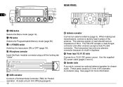
... button Switches the transmit frequency and receive frequency when operating with a transmit offset or a split memory channel {page 27}. o LOW button Selects High, Mid, or Low transmit output power {page 18}. !0 SQL controls Adjusts the squelch threshold level {page 16}. Turn the left button (VHF) or the right button (UHF) depending on which band you want to mute speaker output while no stations are available using the front panel 11 buttons or the microphone keys...
... button Switches the transmit frequency and receive frequency when operating with a transmit offset or a split memory channel {page 27}. o LOW button Selects High, Mid, or Low transmit output power {page 18}. !0 SQL controls Adjusts the squelch threshold level {page 16}. Turn the left button (VHF) or the right button (UHF) depending on which band you want to mute speaker output while no stations are available using the front panel 11 buttons or the microphone keys...
User Manual
Page 18
... clearer audio. Accepts a 6-pin mini DIN plug {page 6}. 12 REAR PANEL q Antenna connector Connect an external antenna {page 5}. The TM-V7E accepts a male N-type connector and other versions accept a male PL-259 connector. These jacks accept a 3.5 mm (1/8") diameter, 2-conductor plug. This transceiver has only one antenna connector because of a built-in place of 50 Ω. w Power Input 13.8 V DC cable Connect to a 13.8 V DC power source. 1 CALL 2 3 4 5 6 7 !3 MNU button 8 Selects the Menu mode {page...
... clearer audio. Accepts a 6-pin mini DIN plug {page 6}. 12 REAR PANEL q Antenna connector Connect an external antenna {page 5}. The TM-V7E accepts a male N-type connector and other versions accept a male PL-259 connector. These jacks accept a 3.5 mm (1/8") diameter, 2-conductor plug. This transceiver has only one antenna connector because of a built-in place of 50 Ω. w Power Input 13.8 V DC cable Connect to a 13.8 V DC power source. 1 CALL 2 3 4 5 6 7 !3 MNU button 8 Selects the Menu mode {page...

User Manual
Page 23
See "KEYPAD DIRECT 3 ENTRY" {page 74}. 4 5 ■ Microphone [UP]/[DWN] Buttons 6 Using Mic [UP]/[DWN] for further information. 2 • You can also select frequencies via the microphone keypad (MC-53DM only). To change frequencies in steps of 1 MHz, press [MHz] first. Pressing [F] cancels the 10 MHz function; pressing [MHz] starts the 1 MHz function. • If you cannot select a particular receive frequency, the frequency step size needs to...
See "KEYPAD DIRECT 3 ENTRY" {page 74}. 4 5 ■ Microphone [UP]/[DWN] Buttons 6 Using Mic [UP]/[DWN] for further information. 2 • You can also select frequencies via the microphone keypad (MC-53DM only). To change frequencies in steps of 1 MHz, press [MHz] first. Pressing [F] cancels the 10 MHz function; pressing [MHz] starts the 1 MHz function. • If you cannot select a particular receive frequency, the frequency step size needs to...

User Manual
Page 24
... reduce intelligibility of your signal 9 at the receiving station. 10 • The RF power meter shows the relative transmit output power. 11 2 When you press [LOW], the transmit power is necessary. High Medium Low (No Indicator) ("M") ("L") CAUTION: ◆ DO NOT TRANSMIT WITH HIGH OUTPUT POWER FOR EXTENDED PERIODS. CALL VOL SQL • Each time you finish speaking, release Mic [PTT]. 12 13...
... reduce intelligibility of your signal 9 at the receiving station. 10 • The RF power meter shows the relative transmit output power. 11 2 When you press [LOW], the transmit power is necessary. High Medium Low (No Indicator) ("M") ("L") CAUTION: ◆ DO NOT TRANSMIT WITH HIGH OUTPUT POWER FOR EXTENDED PERIODS. CALL VOL SQL • Each time you finish speaking, release Mic [PTT]. 12 13...

User Manual
Page 27
... 1 Beep Volume Level 1 (min.) ~ 7 (max.) / OFF Level 5 66 13 2 Speaker Configuration Mode 1/ mode 2 Mode 1 76 14 3 Voice Synthesizer English/ Japanese/ OFF (Only when the optional VS-3 is installed.) 15 1 Data Transfer Rate 1200 bps/ 9600 bps English 82 15 1200 bps 79 16 2 Data TX/RX Band ON/ OFF OFF 79 17 16 1 Microphone Control ON/ OFF 2 ~ 5 Programmable Function Keys See reference...
... 1 Beep Volume Level 1 (min.) ~ 7 (max.) / OFF Level 5 66 13 2 Speaker Configuration Mode 1/ mode 2 Mode 1 76 14 3 Voice Synthesizer English/ Japanese/ OFF (Only when the optional VS-3 is installed.) 15 1 Data Transfer Rate 1200 bps/ 9600 bps English 82 15 1200 bps 79 16 2 Data TX/RX Band ON/ OFF OFF 79 17 16 1 Microphone Control ON/ OFF 2 ~ 5 Programmable Function Keys See reference...
User Manual
Page 42
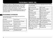
... settings are the type 4 who likes the many features offered by the VHF and UHF bands: 10 11 TX band Control band 12 Automatic Power Off Automatic Band Change Tone frequency Tone status Offset direction Automatic Repeater Offset Upper frequency limit (for Programmable VFO) CTCSS frequency CTCSS status Offset status Reverse status Lower frequency limit (for Programmable VFO) 13 Time-Out Timer Display Dimmer Scan resume method S-meter Squelch 14 Auto...
... settings are the type 4 who likes the many features offered by the VHF and UHF bands: 10 11 TX band Control band 12 Automatic Power Off Automatic Band Change Tone frequency Tone status Offset direction Automatic Repeater Offset Upper frequency limit (for Programmable VFO) CTCSS frequency CTCSS status Offset status Reverse status Lower frequency limit (for Programmable VFO) 13 Time-Out Timer Display Dimmer Scan resume method S-meter Squelch 14 Auto...

User Manual
Page 43
... of how you can quickly change the settings after dark. 5 Solution: 6 In two PM channels, store the same operating data such 7 as frequency, offset, DTSS code, etc., and store different 8 settings for day or night 9 operating. 10 Situation 3: 11 You cannot figure out how you might use the transceiver. Then you can quickly recall the best settings for the Display Dimmer and Beep functions...
... of how you can quickly change the settings after dark. 5 Solution: 6 In two PM channels, store the same operating data such 7 as frequency, offset, DTSS code, etc., and store different 8 settings for day or night 9 operating. 10 Situation 3: 11 You cannot figure out how you might use the transceiver. Then you can quickly recall the best settings for the Display Dimmer and Beep functions...

User Manual
Page 47
... number of channels is 49. 13 5 Press [MNU] to monitor frequencies near the current operating frequency. The default number of channels. You will see up to receive this position to 14 segments, for each channel, that represent 7 S-meter levels (2 segments per level). Visual Scan graphically and simultaneously shows how all frequencies in the selected range are on the air, Visual Scan allows you to exit Menu mode...
... number of channels is 49. 13 5 Press [MNU] to monitor frequencies near the current operating frequency. The default number of channels. You will see up to receive this position to 14 segments, for each channel, that represent 7 S-meter levels (2 segments per level). Visual Scan graphically and simultaneously shows how all frequencies in the selected range are on the air, Visual Scan allows you to exit Menu mode...

User Manual
Page 48
... Tuning control or press Mic [UP]/[DWN]. 13 • The displayed frequency changes and the cursor 14 moves. • Press [SET] to use this frequency, press [PAUSE] to halt Scan. • Memory Recall or Call Channel mode • The VHF band, VFO mode, and a frequency in the range 118 MHz to 136 MHz were selected. ◆ Depending on conditions, Visual Scan and the conventional S-meter may indicate different signal...
... Tuning control or press Mic [UP]/[DWN]. 13 • The displayed frequency changes and the cursor 14 moves. • Press [SET] to use this frequency, press [PAUSE] to halt Scan. • Memory Recall or Call Channel mode • The VHF band, VFO mode, and a frequency in the range 118 MHz to 136 MHz were selected. ◆ Depending on conditions, Visual Scan and the conventional S-meter may indicate different signal...

User Manual
Page 58
... Mic [PTT] transmits the DTSS signal after a 2 short delay. The delay time is 350 ms 4 during simplex operation. 5 When using repeaters with long response times, this delay helps the repeater avoid losing a 3 portion of the DTSS code. When using a transmit offset or a split frequency, you can select either 350 ms (default) or 550 ms. 6 1 Press [MNU] to enter Menu mode. 7 2 Select Menu No. 12 (Code Squelch...
... Mic [PTT] transmits the DTSS signal after a 2 short delay. The delay time is 350 ms 4 during simplex operation. 5 When using repeaters with long response times, this delay helps the repeater avoid losing a 3 portion of the DTSS code. When using a transmit offset or a split frequency, you can select either 350 ms (default) or 550 ms. 6 1 Press [MNU] to enter Menu mode. 7 2 Select Menu No. 12 (Code Squelch...

User Manual
Page 62
... the Page codes after Page has opened the squelch, no signal is received for more than 2 seconds, the squelch will close. 2 ◆ "Err" appears on the display if your Station code, Page Lockout does not inhibit the transceiver from receiving specific Group codes. Note: You cannot lock out memory channel 0. The delay time is 350 ms 12 during simplex operation. 13 When using repeaters with DTSS...
... the Page codes after Page has opened the squelch, no signal is received for more than 2 seconds, the squelch will close. 2 ◆ "Err" appears on the display if your Station code, Page Lockout does not inhibit the transceiver from receiving specific Group codes. Note: You cannot lock out memory channel 0. The delay time is 350 ms 12 during simplex operation. 13 When using repeaters with DTSS...

User Manual
Page 65
... all digits entered. 10 7 Press [SET] to complete setting. 11 • The entered DTMF number appears with a maximum of 16 digits in memory. 1 Press [MNU] to enter Menu mode. 2 Select Menu No. 7 (DTMF Memory). CALL VOL SQL 4 Press a numeric key 0 to 9 on the Mic keypad to select the desired channel. 1 5 Press [SET]. 2 • The display for entering a DTMF number appears. 3 CALL 4 5 VOL SQL 6 7 6 Use the...
... all digits entered. 10 7 Press [SET] to complete setting. 11 • The entered DTMF number appears with a maximum of 16 digits in memory. 1 Press [MNU] to enter Menu mode. 2 Select Menu No. 7 (DTMF Memory). CALL VOL SQL 4 Press a numeric key 0 to 9 on the Mic keypad to select the desired channel. 1 5 Press [SET]. 2 • The display for entering a DTMF number appears. 3 CALL 4 5 VOL SQL 6 7 6 Use the...

User Manual
Page 88
... Synthesizer function after installing the optional VS-3 unit, access Item No. 3 (Voice) under Menu No. 14 (Audio), and select OFF. ◆ While using Transceiver Lock or All Lock, the transceiver makes an announcement only when pressing Mic [6] in Microphone Control mode {page 77} or the PF key programmed with Voice {page 72}. • In VFO mode, announces the VFO frequency on the Control band beginning with Voice...
... Synthesizer function after installing the optional VS-3 unit, access Item No. 3 (Voice) under Menu No. 14 (Audio), and select OFF. ◆ While using Transceiver Lock or All Lock, the transceiver makes an announcement only when pressing Mic [6] in Microphone Control mode {page 77} or the PF key programmed with Voice {page 72}. • In VFO mode, announces the VFO frequency on the Control band beginning with Voice...
User Manual
Page 94
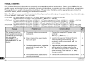
... will not 1 The power cable was connected 1 Connect the supplied DC power cable 3, 4 12 power up , accidental incorrect control settings, or operator error due to incomplete programming. After inspecting and correcting any problems, install a new fuse(s) with the same ratings. 5 16 3 The front panel was not 4 Connect the connectorized cable correctly. 3, 4 20 correctly connected. 21 88 Continued This is defective. 4 Note: When 2 frequencies are received in the same band and these frequencies have relationships per...
... will not 1 The power cable was connected 1 Connect the supplied DC power cable 3, 4 12 power up , accidental incorrect control settings, or operator error due to incomplete programming. After inspecting and correcting any problems, install a new fuse(s) with the same ratings. 5 16 3 The front panel was not 4 Connect the connectorized cable correctly. 3, 4 20 correctly connected. 21 88 Continued This is defective. 4 Note: When 2 frequencies are received in the same band and these frequencies have relationships per...

User Manual
Page 99
... 58 Channel Display Function .... 34 Continuous Tone Coded Squelch System (CTCSS) ... 49 Display Changing Conditions ........ 70 Demonstration mode ........ 69 Dual Band RX 63 Dual Tone Multi-Frequency (DTMF) Functions Confirming Stored Numbers 60 Making Calls 58 Storing Numbers 59 Transmitting Stored Numbers 60 Dual Tone Squelch System (DTSS) Storing Codes 50 Using 51 Frequencies, Selecting Microphone [UP]/[DWN] ... 17 Tuning Control 17 Frequency Step Size 65 Fuses, Replacing 5 Installation Antenna 5 DC Power Cable, Fixed Station 4 DC Power Cable, Mobile...
... 58 Channel Display Function .... 34 Continuous Tone Coded Squelch System (CTCSS) ... 49 Display Changing Conditions ........ 70 Demonstration mode ........ 69 Dual Band RX 63 Dual Tone Multi-Frequency (DTMF) Functions Confirming Stored Numbers 60 Making Calls 58 Storing Numbers 59 Transmitting Stored Numbers 60 Dual Tone Squelch System (DTSS) Storing Codes 50 Using 51 Frequencies, Selecting Microphone [UP]/[DWN] ... 17 Tuning Control 17 Frequency Step Size 65 Fuses, Replacing 5 Installation Antenna 5 DC Power Cable, Fixed Station 4 DC Power Cable, Mobile...


