
User Manual
Page 1
STEREO POWER AMPLIFIER M-A300 M-A100 INSTRUCTION MANUAL KENWOOD CORPORATION This instruction manual is used for two models. B60-3340-00 (K, P, Y, T, M, C, X, I) MA CH MC 98/12 11 10 9 8 7 6 5 4 3 2 1 97/12 11 10 9 8 7 6 5 Model availability and features (functions) may differ depending on the country and sales area.
STEREO POWER AMPLIFIER M-A300 M-A100 INSTRUCTION MANUAL KENWOOD CORPORATION This instruction manual is used for two models. B60-3340-00 (K, P, Y, T, M, C, X, I) MA CH MC 98/12 11 10 9 8 7 6 5 4 3 2 1 97/12 11 10 9 8 7 6 5 Model availability and features (functions) may differ depending on the country and sales area.
User Manual
Page 2
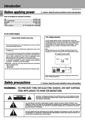
... switch. Note: Our warranty does not cover damage caused by inadvertent connection to the mains supply. NO USER-SERVICEABLE PARTS INSIDE, REFER SERVICING TO QUALIFIED SERVICE PERSONNEL. IMPORTANT: The wires in the mains lead are designed for the power points in your home or the cable is shipped. For replacement, use only a 13-Amp ASTA-approved (BS1362) fuse. 2. If nonetheless the mains plug is cut off , remove...
... switch. Note: Our warranty does not cover damage caused by inadvertent connection to the mains supply. NO USER-SERVICEABLE PARTS INSIDE, REFER SERVICING TO QUALIFIED SERVICE PERSONNEL. IMPORTANT: The wires in the mains lead are designed for the power points in your home or the cable is shipped. For replacement, use only a 13-Amp ASTA-approved (BS1362) fuse. 2. If nonetheless the mains plug is cut off , remove...
User Manual
Page 3
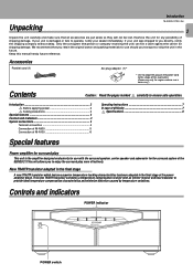
... of the power amplifier block. Only the consignee (the person or company receiving the unit) can file a claim against the carrier for surround play more effectively. Controls and indicators POWER indicator POWER -ON -OFF POWER AMPLIFIER POWER switch Introduction ...2 Before applying power 2 Safety precautions 2 Special features 3 Controls and indicators 3 System connections 4 Terminal connection 4 Connection of M-A300 5 Connection of M-A100 6 Special features Operating instructions 7 In case of difficulty 7 Specifications 8 Power amplifier for shipping damage...
... of the power amplifier block. Only the consignee (the person or company receiving the unit) can file a claim against the carrier for surround play more effectively. Controls and indicators POWER indicator POWER -ON -OFF POWER AMPLIFIER POWER switch Introduction ...2 Before applying power 2 Safety precautions 2 Special features 3 Controls and indicators 3 System connections 4 Terminal connection 4 Connection of M-A300 5 Connection of M-A100 6 Special features Operating instructions 7 In case of difficulty 7 Specifications 8 Power amplifier for shipping damage...
User Manual
Page 4
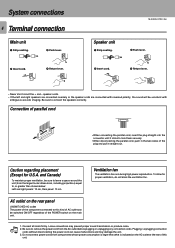
... rear panel UNSWITCHED AC outlet The power of the POWER switch on the main unit. To allow for U.S.A. System connections 4 Terminal connection Main unit 1 Strip coating. 2 Push lever. 3 Insert cord. 4 Return lever. AC outlet on the AC outlet at the rear of this kind of parallel cord • When connecting the parallel cord, insert the plug straight into the connector until it clicks to connect the speakers...
... rear panel UNSWITCHED AC outlet The power of the POWER switch on the main unit. To allow for U.S.A. System connections 4 Terminal connection Main unit 1 Strip coating. 2 Push lever. 3 Insert cord. 4 Return lever. AC outlet on the AC outlet at the rear of this kind of parallel cord • When connecting the parallel cord, insert the plug straight into the connector until it clicks to connect the speakers...
User Manual
Page 5
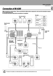
... countries CONNECT WITH AV CONTROL CENTER SUB FRONT SURROUND WOOFER + - R R SW (6-16Ω) SPEAKERS When using the speaker system S-F700 Ventilation fan Center speaker CENTER SURROUND FRONT + - (6-16Ω) C L L SPEAKERS −+ See-through UNSWITCHED White lined To AC wall outlet −+ −+ Subwoofer Front speakers Right Left −+ −+ −+ −+ The shape of the speakers are completed. Note When connecting the related system components, refer also to the instruction manuals of M-A300 5 Make connections...
... countries CONNECT WITH AV CONTROL CENTER SUB FRONT SURROUND WOOFER + - R R SW (6-16Ω) SPEAKERS When using the speaker system S-F700 Ventilation fan Center speaker CENTER SURROUND FRONT + - (6-16Ω) C L L SPEAKERS −+ See-through UNSWITCHED White lined To AC wall outlet −+ −+ Subwoofer Front speakers Right Left −+ −+ −+ −+ The shape of the speakers are completed. Note When connecting the related system components, refer also to the instruction manuals of M-A300 5 Make connections...
User Manual
Page 6
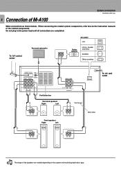
...;) SPEAKERS Ventilation fan CENTER FRONT + - (6-16Ω) C L SPEAKERS UNSWITCHED Surround speakers Right Left See-through To AC wall outlet −+ Front speakers Right Left −+ White lined −+ −+ Note The shape of the related components. When connecting the related system components, refer also to the instruction manuals of the speakers are completed. 6 Connection of M-A100 System connections M-A300/A100 (En) Make connections as shown below. To AV control center Powered subwoofer −...
...;) SPEAKERS Ventilation fan CENTER FRONT + - (6-16Ω) C L SPEAKERS UNSWITCHED Surround speakers Right Left See-through To AC wall outlet −+ Front speakers Right Left −+ White lined −+ −+ Note The shape of the related components. When connecting the related system components, refer also to the instruction manuals of the speakers are completed. 6 Connection of M-A100 System connections M-A300/A100 (En) Make connections as shown below. To AV control center Powered subwoofer −...
User Manual
Page 7
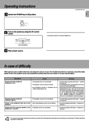
... Note the plastic components. POWER -ON -OFF 2 Turn on the panel lights up. 3 Play a music source. Operating instructions 1 Switch the POWER key to page 4. Sound is not produced from the surround speaker is not • A speaker cord is activated due to internal temperature rise. • Connect them properly referring to "System connections". Do not use contact cleaners because it properly referring to "System connections". Improve the unit installation referring to ON position. Sound from one of...
... Note the plastic components. POWER -ON -OFF 2 Turn on the panel lights up. 3 Play a music source. Operating instructions 1 Switch the POWER key to page 4. Sound is not produced from the surround speaker is not • A speaker cord is activated due to internal temperature rise. • Connect them properly referring to "System connections". Do not use contact cleaners because it properly referring to "System connections". Improve the unit installation referring to ON position. Sound from one of...
User Manual
Page 8
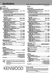
...) 8 AUDIO section Effective output power during STEREO operation [For the U.S.A. at 6 100 W + 100 W Rated output power during STEREO operation [Except for information or service on this reason specifications may not be changed without notice. 2. Refer to 20 kHz with no more than 0.09 % total harmonic distortion.(FTC) 100 watts per channel minimum RMS, both channels driven, at 6 Ω from 40 Hz to the model and serial numbers whenever...
...) 8 AUDIO section Effective output power during STEREO operation [For the U.S.A. at 6 100 W + 100 W Rated output power during STEREO operation [Except for information or service on this reason specifications may not be changed without notice. 2. Refer to 20 kHz with no more than 0.09 % total harmonic distortion.(FTC) 100 watts per channel minimum RMS, both channels driven, at 6 Ω from 40 Hz to the model and serial numbers whenever...


