Instruction Manual
Page 3
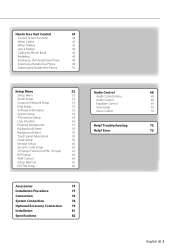
...Phone 50 Setup Menu 52 Audio Control 68 Setup Menu 52 Audio Control menu 68 Audio Setup 52 Audio Control 68 Crossover Network Setup 53 Equalizer Control 69 iPod Setup 53 Tone setup 70 Software Information 53 Zone Control 70 System Setup 54 AV ...(Function of PAL TV type) 63 RDS Setup 64 AMP Control 64 Setup Memory 65 EXT SW Setup 66 Accessories 74 Installation Procedure 75 Connection 76 System Connection 78 Optional Accessory Connection 79 Installation 81 Specifications 82 English 3 Troubleshooting 72 Background Delete Background Select...
...Phone 50 Setup Menu 52 Audio Control 68 Setup Menu 52 Audio Control menu 68 Audio Setup 52 Audio Control 68 Crossover Network Setup 53 Equalizer Control 69 iPod Setup 53 Tone setup 70 Software Information 53 Zone Control 70 System Setup 54 AV ...(Function of PAL TV type) 63 RDS Setup 64 AMP Control 64 Setup Memory 65 EXT SW Setup 66 Accessories 74 Installation Procedure 75 Connection 76 System Connection 78 Optional Accessory Connection 79 Installation 81 Specifications 82 English 3 Troubleshooting 72 Background Delete Background Select...
Instruction Manual
Page 6
...1998 or later can use your Kenwood dealer for the applicable Kenwood disc changers. Set the "O-N" Switch to the "N" position for connectable models of water splashing. • When replacing a fuse, only use the wrong screws, you connect them incorrectly. 6 KOS-V500 For safety's sake, leave the... mounting and wiring work to professionals. 2CAUTION To prevent damage to the machine, take the following precautions: • Make sure to ground the unit to a negative 12V DC power supply. • Do not install the unit in ...
...1998 or later can use your Kenwood dealer for the applicable Kenwood disc changers. Set the "O-N" Switch to the "N" position for connectable models of water splashing. • When replacing a fuse, only use the wrong screws, you connect them incorrectly. 6 KOS-V500 For safety's sake, leave the... mounting and wiring work to professionals. 2CAUTION To prevent damage to the machine, take the following precautions: • Make sure to ground the unit to a negative 12V DC power supply. • Do not install the unit in ...
Instruction Manual
Page 7
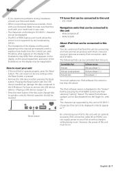
... to this manual are examples used to explain more clearly how the controls are used. English 7 Pressing the Reset button with Dock connector using an optional accessory iPod connection cable (KCA-iP300V ). TV tuner that can be connected to this unit • KTC-V300P Navigation...unit You can control an iPod from this unit is pressed. • Remove the USB device before pressing the Reset button. Normal operation should be displayed correctly appear as charge it while playing music. Notes • If you experience problems during installation, consult your Kenwood dealer. •...
... to this manual are examples used to explain more clearly how the controls are used. English 7 Pressing the Reset button with Dock connector using an optional accessory iPod connection cable (KCA-iP300V ). TV tuner that can be connected to this unit • KTC-V300P Navigation...unit You can control an iPod from this unit is pressed. • Remove the USB device before pressing the Reset button. Normal operation should be displayed correctly appear as charge it while playing music. Notes • If you experience problems during installation, consult your Kenwood dealer. •...
Instruction Manual
Page 9
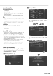
Extensions Picture files must have no compensation for AV-IN, Inner AMP, and Tuner source when the unit is installed or the reset button is pressed. 1 Start system start up by referring to (page 54). 3 Returns to the original screen System start up setting You .... The files can be displayed or operated (e.g.: rotation display) properly. We shall have one of the following extensions: jpg, jpeg, jpe About USB device • Install the USB device in the place where it will not prevent you from driving your vehicle properly. • You cannot connect a USB device via a USB...
Extensions Picture files must have no compensation for AV-IN, Inner AMP, and Tuner source when the unit is installed or the reset button is pressed. 1 Start system start up by referring to (page 54). 3 Returns to the original screen System start up setting You .... The files can be displayed or operated (e.g.: rotation display) properly. We shall have one of the following extensions: jpg, jpeg, jpe About USB device • Install the USB device in the place where it will not prevent you from driving your vehicle properly. • You cannot connect a USB device via a USB...
Instruction Manual
Page 11
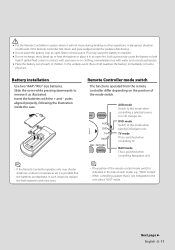
...Slide the cover while pressing downwards to this mode when controlling a selected source or a CD changer etc. DVD mode Switch to remove it will not move during braking or other operations. Next page 3 English 11 Battery installation Use two "AAA"/"R03"-size batteries. Insert the ...to leak fluid. In the unlikely event that a child swallows the battery, immediately consult a physician. Remote Controller mode switch The functions operated from the remote controller differ depending on clothing, immediately rinse with your eyes or on the position of children. Such actions may ...
...Slide the cover while pressing downwards to this mode when controlling a selected source or a CD changer etc. DVD mode Switch to remove it will not move during braking or other operations. Next page 3 English 11 Battery installation Use two "AAA"/"R03"-size batteries. Insert the ...to leak fluid. In the unlikely event that a child swallows the battery, immediately consult a physician. Remote Controller mode switch The functions operated from the remote controller differ depending on clothing, immediately rinse with your eyes or on the position of children. Such actions may ...
Instruction Manual
Page 75
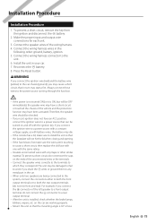
... one with the same rating. • Insulate unconnected wires with the ignition key. on and off with vinyl tape or other similar material. Installation Procedure Installation Procedure 1. For example, if you connect the ignition wire to a power source with a constant voltage supply, as with battery wires, the ...a short-circuit or touched the chassis of the left speaker to work if you may cause a short circuit, that the mounting angle is installed, check whether the brake lamps, blinkers, wipers, etc. The unit may be turned on the car are being connected to the system, ...
... one with the same rating. • Insulate unconnected wires with the ignition key. on and off with vinyl tape or other similar material. Installation Procedure Installation Procedure 1. For example, if you connect the ignition wire to a power source with a constant voltage supply, as with battery wires, the ...a short-circuit or touched the chassis of the left speaker to work if you may cause a short circuit, that the mounting angle is installed, check whether the brake lamps, blinkers, wipers, etc. The unit may be turned on the car are being connected to the system, ...
Instruction Manual
Page 81
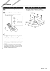
... temporarily and verify that do not obstruct driving. Installation for Remote control sensor 1 Wipe off . • Do not install the Remote control sensor in places (such as on a flat surface. Otherwise, the Remote control sensor will become deformed and unusable. • Install the Remote control sensor in the specified place with the doublesided adhesive tape. English 81...
... temporarily and verify that do not obstruct driving. Installation for Remote control sensor 1 Wipe off . • Do not install the Remote control sensor in places (such as on a flat surface. Otherwise, the Remote control sensor will become deformed and unusable. • Install the Remote control sensor in the specified place with the doublesided adhesive tape. English 81...
Instruction Manual
Page 83
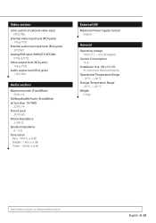
... : 1 kHz ± 8 dB Treble : 10 kHz ± 8 dB External SW Maximum Power Supply Current : 500mA General Operating voltage : 14.4 V (11 - 16 V allowable) Current Consumption : 15 A Installation Size (W × H × D) : 319.2mm×41.0mm×232.0mm Operational Temperature Range : -10 °C - +60 °C Storage Temperature Range : -20 °C - +85 °...
... : 1 kHz ± 8 dB Treble : 10 kHz ± 8 dB External SW Maximum Power Supply Current : 500mA General Operating voltage : 14.4 V (11 - 16 V allowable) Current Consumption : 15 A Installation Size (W × H × D) : 319.2mm×41.0mm×232.0mm Operational Temperature Range : -10 °C - +60 °C Storage Temperature Range : -20 °C - +85 °...


