Instruction Manual
Page 2
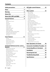
... Play Random Play Magazine Random Play Disc Random Play Folder Select Switching the Play mode Letter Seek Text/Title Scroll Accessories/ Installation Procedure 32 Connecting Wires to Terminals Installation Removing the Unit Troubleshooting Guide Specifications 33 34 36 37 40 2 | English Frequency Offset AMP Control CRSC (Clean Reception System Circuit) Receive...
... Play Random Play Magazine Random Play Disc Random Play Folder Select Switching the Play mode Letter Seek Text/Title Scroll Accessories/ Installation Procedure 32 Connecting Wires to Terminals Installation Removing the Unit Troubleshooting Guide Specifications 33 34 36 37 40 2 | English Frequency Offset AMP Control CRSC (Clean Reception System Circuit) Receive...
Instruction Manual
Page 32
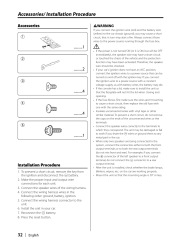
... both the front output terminals or to both the rear output terminals (do not mix front and rear). Installation Procedure 1. battery. 2. Connect the wiring harness connector to a rear output terminal. • After the unit is installed, check whether the brake lamps, blinkers, wipers, etc. If you... be damaged or fail to work if you share the - connector to the unit. 6. Always connect those wires to the car chassis (ground), you connect the ignition wire (red) and the battery wire (yellow) to the power source running through the fuse box. battery. 8. For example, if you connect...
... both the front output terminals or to both the rear output terminals (do not mix front and rear). Installation Procedure 1. battery. 2. Connect the wiring harness connector to a rear output terminal. • After the unit is installed, check whether the brake lamps, blinkers, wipers, etc. If you... be damaged or fail to work if you share the - connector to the unit. 6. Always connect those wires to the car chassis (ground), you connect the ignition wire (red) and the battery wire (yellow) to the power source running through the fuse box. battery. 8. For example, if you connect...
Instruction Manual
Page 33
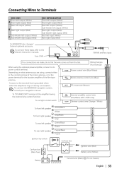
...Car fuse box (Main fuse) Ignition wire (Red) Battery wire (Yellow) Battery ³ Ground wire (Black) · (To car chassis) q 2%!22 2%!2, &2/.42 &2/.4, To front left output (White) C Sub Woofer right output (Red) To KENWOOD disc changer/ External optional accessory To connect... these leads, refer to the relevant instruction manuals. Connecting Wires to Terminals KDC-X589 Front left output (White) A Front right output (Red) Rear left ...
...Car fuse box (Main fuse) Ignition wire (Red) Battery wire (Yellow) Battery ³ Ground wire (Black) · (To car chassis) q 2%!22 2%!2, &2/.42 &2/.4, To front left output (White) C Sub Woofer right output (Red) To KENWOOD disc changer/ External optional accessory To connect... these leads, refer to the relevant instruction manuals. Connecting Wires to Terminals KDC-X589 Front left output (White) A Front right output (Red) Rear left ...
Instruction Manual
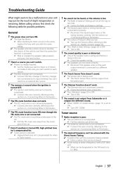
Page 37
...9758; Connect the Disc changer. See the section on . ✔ The values of the vehicle, and then the protection function is activated. ☞ Wire or insulate the speaker cable properly and press the reset button. The Touch Sensor Tone doesn't sound. ✔ The preout jack is being pinched by... a frequency with a 0.01 MHz unit. ☞ What can 't switch to each output terminal is not output from the metal part of the speaker wires is selected. ☞ High-pitched tone isn't compensated for possible problems. ? The sound quality is poor or distorted. ✔ One of the car....
...9758; Connect the Disc changer. See the section on . ✔ The values of the vehicle, and then the protection function is activated. ☞ Wire or insulate the speaker cable properly and press the reset button. The Touch Sensor Tone doesn't sound. ✔ The preout jack is being pinched by... a frequency with a 0.01 MHz unit. ☞ What can 't switch to each output terminal is not output from the metal part of the speaker wires is selected. ☞ High-pitched tone isn't compensated for possible problems. ? The sound quality is poor or distorted. ✔ One of the car....


