Instruction Manual
Page 1
Refer to read through this instruction manual. Model KAC-X522 Serial number US Residence Only Register Online Register your Kenwood dealer for information or service on the warranty card, and in the space provided below. KAC-X522 STEREO/BRIDGEABLE POWER AMPLIFIER 7 page 2-9 INSTRUCTION MANUAL AMPLIFICATEUR DE PUISSANCE STEREO/COMPATIBLE 7 page 10-17 MODE D'EMPLOI ESTÉRO...
Refer to read through this instruction manual. Model KAC-X522 Serial number US Residence Only Register Online Register your Kenwood dealer for information or service on the warranty card, and in the space provided below. KAC-X522 STEREO/BRIDGEABLE POWER AMPLIFIER 7 page 2-9 INSTRUCTION MANUAL AMPLIFICATEUR DE PUISSANCE STEREO/COMPATIBLE 7 page 10-17 MODE D'EMPLOI ESTÉRO...
Instruction Manual
Page 2
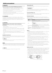
... a time. Changes or modifications to install a protective fuse in the unit to the amplifier. 4Ω 4Ω 8 Ω 4Ω 4Ω 2 Ω Combined impedance 2 English Available Control Units: A Kenwood's LX-Bus supporting Center Unit released in the instruction manual. The operations of the (...buzzing noise is heard from various problems. When Protection operates, the display informs you experience problems during use a new one power amplifier are explained in a spot exposed to the speaker's output. When the unit has failed and direct current voltage is connected to ...
... a time. Changes or modifications to install a protective fuse in the unit to the amplifier. 4Ω 4Ω 8 Ω 4Ω 4Ω 2 Ω Combined impedance 2 English Available Control Units: A Kenwood's LX-Bus supporting Center Unit released in the instruction manual. The operations of the (...buzzing noise is heard from various problems. When Protection operates, the display informs you experience problems during use a new one power amplifier are explained in a spot exposed to the speaker's output. When the unit has failed and direct current voltage is connected to ...
Instruction Manual
Page 3
... substances that electrical equipment such as a gasoline tank, brake pipe, or wiring harness, and be damaged. • Install this order. 6. Install the amplifier in a place where people, resins, and other damage. • Do not install near the dashboard, rear tray, or air bag safety parts. &#...select the proper setting and connection. 1. Set the unit according to prevent short circuits. 2. Connect the input and output wires of the amplifier will become hot during use. Connect the speaker wires. 5. Once installed, do not place any object on the opposite side such as ...
... substances that electrical equipment such as a gasoline tank, brake pipe, or wiring harness, and be damaged. • Install this order. 6. Install the amplifier in a place where people, resins, and other damage. • Do not install near the dashboard, rear tray, or air bag safety parts. &#...select the proper setting and connection. 1. Set the unit according to prevent short circuits. 2. Connect the input and output wires of the amplifier will become hot during use. Connect the speaker wires. 5. Once installed, do not place any object on the opposite side such as ...
Instruction Manual
Page 4
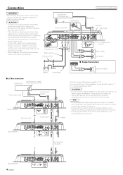
...connectors separately. You can cause this limit, you cannot control amps from the Center Unit. • If you operate any of the Master amplifier to the Center Unit. You must connect any of the same rating. • Check that the brake lamps, winkers, and wipers work...9632; Bridged Connections Battery Ground wire* Speaker (Bridged) ■ LX-Bus connection CENTER UNIT To Kenwood disc changer/ External optional accessory Power control wire Control cable (option) 30 30 Master amplifier Extension wire* 456 23 23 78 "0" 456 ID NUMBER 78 S-video cable* RCA cable* Set ...
...connectors separately. You can cause this limit, you cannot control amps from the Center Unit. • If you operate any of the Master amplifier to the Center Unit. You must connect any of the same rating. • Check that the brake lamps, winkers, and wipers work...9632; Bridged Connections Battery Ground wire* Speaker (Bridged) ■ LX-Bus connection CENTER UNIT To Kenwood disc changer/ External optional accessory Power control wire Control cable (option) 30 30 Master amplifier Extension wire* 456 23 23 78 "0" 456 ID NUMBER 78 S-video cable* RCA cable* Set ...
Instruction Manual
Page 5
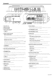
...indicator Lights when the POWER switch is not output.) ) INPUT SENSITIVITY control Set this control according to use the unit as a high-power monaural amplifier. (The input right signal is turned On. NOTE Controls the unit power. When multiple speakers are used for each channel. • Bridged Connections...: When you have set with all the systems. 5 Speaker output terminals • Stereo Connections: When you use as a stereo amplifier, stereo connections are to this unit. The speaker output is possible even while OFF. * ISF (infrasonic filter) switch When this position...
...indicator Lights when the POWER switch is not output.) ) INPUT SENSITIVITY control Set this control according to use the unit as a high-power monaural amplifier. (The input right signal is turned On. NOTE Controls the unit power. When multiple speakers are used for each channel. • Bridged Connections...: When you have set with all the systems. 5 Speaker output terminals • Stereo Connections: When you use as a stereo amplifier, stereo connections are to this unit. The speaker output is possible even while OFF. * ISF (infrasonic filter) switch When this position...
Instruction Manual
Page 6
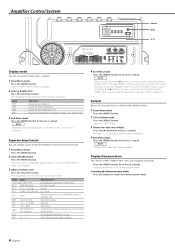
...can recall the value when message "LOAD" is initialized. 4 Exit Menu mode Press the [MENU] button for at least 1 second. To call the Amplifier Control's values, hold down the [2] button 3 or more seconds during ID number display ("AMP"). Message "----" is displayed, and the value is displayed....The indicator flashes in 3 steps: "FAST", "SLOW" or "OFF". 3 Exit Menu mode Press the [MENU] button for at least 1 second. Amplifier Control System FAN VOLT TEMP CURR Indicator MENU 2 / 3 Display mode You can set up the display items as follows. NOTE When the internal temperature ...
...can recall the value when message "LOAD" is initialized. 4 Exit Menu mode Press the [MENU] button for at least 1 second. To call the Amplifier Control's values, hold down the [2] button 3 or more seconds during ID number display ("AMP"). Message "----" is displayed, and the value is displayed....The indicator flashes in 3 steps: "FAST", "SLOW" or "OFF". 3 Exit Menu mode Press the [MENU] button for at least 1 second. Amplifier Control System FAN VOLT TEMP CURR Indicator MENU 2 / 3 Display mode You can set up the display items as follows. NOTE When the internal temperature ...
Instruction Manual
Page 7
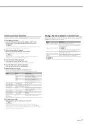
... Select the AMP Control mode by following the instructions given on the Operation Manual of the Center Unit. 2 Select an amp number to the Kenwood's dealership. NOTE When the Center Unit is in contact with the Amp Control, an error status of the unit is generated to the speaker's... Amp Control mode by the Center Unit. Display Informations "AMP × E-01"/"AMP × COND E-01" When the inside of the amplifier is displayed and you amplify the same frequency as follows. When the unit has failed and direct current voltage is overheating. When the speaker output is in the...
... Select the AMP Control mode by following the instructions given on the Operation Manual of the Center Unit. 2 Select an amp number to the Kenwood's dealership. NOTE When the Center Unit is in contact with the Amp Control, an error status of the unit is generated to the speaker's... Amp Control mode by the Center Unit. Display Informations "AMP × E-01"/"AMP × COND E-01" When the inside of the amplifier is displayed and you amplify the same frequency as follows. When the unit has failed and direct current voltage is overheating. When the speaker output is in the...
Instruction Manual
Page 9
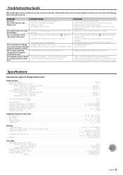
... cord is shorted. • The input sensitivity adjusting control is not set to the correct position. • The speakers wire are connected with the Amplifier Control. SOLUTION • Connect the input (or output) cables. • Check connections by referring to . • Replace the fuse and use .../oct.)...50 - 200 Hz (variable) Infrasonic Filter Frequency (24 dB/oct.)...15 Hz Frequency Response (+0, -3 dB)...5 Hz - 70 kHz Signal to Noise Ratio...105 dB Amplifier Control Section (EQ) Bass frequency ...60 / 80 / 100 / 200 Hz Bass level ...-15 - +15 dB Bass Q factor...1.00 / 1.25 / 1.50 / 2....
... cord is shorted. • The input sensitivity adjusting control is not set to the correct position. • The speakers wire are connected with the Amplifier Control. SOLUTION • Connect the input (or output) cables. • Check connections by referring to . • Replace the fuse and use .../oct.)...50 - 200 Hz (variable) Infrasonic Filter Frequency (24 dB/oct.)...15 Hz Frequency Response (+0, -3 dB)...5 Hz - 70 kHz Signal to Noise Ratio...105 dB Amplifier Control Section (EQ) Bass frequency ...60 / 80 / 100 / 200 Hz Bass level ...-15 - +15 dB Bass Q factor...1.00 / 1.25 / 1.50 / 2....


