

Instruction Manual
Page 1
... with installation and operation procedures will help you call upon your Kenwood dealer for information or service on the warranty card, and in the space provided below. For your records Record the serial number, found on the back of the unit, in the spaces designated on the product. KAC-5203 STEREO/BRIDGEABLE POWER AMPLIFIER 7 page 2-11 INSTRUCTION MANUAL AMPLIFICATEUR DE PUISSANCE STEREO/COMPATIBLE 7 page 12-21 MODE...
... with installation and operation procedures will help you call upon your Kenwood dealer for information or service on the warranty card, and in the space provided below. For your records Record the serial number, found on the back of the unit, in the spaces designated on the product. KAC-5203 STEREO/BRIDGEABLE POWER AMPLIFIER 7 page 2-11 INSTRUCTION MANUAL AMPLIFICATEUR DE PUISSANCE STEREO/COMPATIBLE 7 page 12-21 MODE...

Instruction Manual
Page 2
..., battery, or ground wires, make sure to use automotive-grade wires or other wires with the wrong rating may generate or use radio frequency energy. Changes or modifications to this equipment may cause harmful interference to radio communications, if it is not installed and used in the instruction manual. FCC NOTE This equipment has been tested and found to emit smoke or strange smells, turn off...
..., battery, or ground wires, make sure to use automotive-grade wires or other wires with the wrong rating may generate or use radio frequency energy. Changes or modifications to this equipment may cause harmful interference to radio communications, if it is not installed and used in the instruction manual. FCC NOTE This equipment has been tested and found to emit smoke or strange smells, turn off...

Instruction Manual
Page 3
... unit If the front panel gets dirty, turn the power on if the ground wire is not connected. • Be sure to install a protective fuse in the power cord near the battery. They can cause blown fuses etc. • If a buzzing noise is heard from the speakers when the engine is running, connect a line noise filter (optional) to each amplifier. ■ Speaker Selection • The rated input power of the speakers...
... unit If the front panel gets dirty, turn the power on if the ground wire is not connected. • Be sure to install a protective fuse in the power cord near the battery. They can cause blown fuses etc. • If a buzzing noise is heard from the speakers when the engine is running, connect a line noise filter (optional) to each amplifier. ■ Speaker Selection • The rated input power of the speakers...

Instruction Manual
Page 4
.... 5 Fuse (25 A) 6 Battery terminal 7 Ground terminal 8 Power control terminal Controls the unit ON/OFF. NOTE For the pre-output level or the maximum power output, refer to the in the instruction manual of the center unit. 3 LINE IN terminal 4 Speaker level input terminals NOTE • The genuine-accessory car stereo shall have a maximum power output of no less than 40 W. • Do not connect the speaker output leads from a power amplifier (Optional) to the speaker level input terminals...
.... 5 Fuse (25 A) 6 Battery terminal 7 Ground terminal 8 Power control terminal Controls the unit ON/OFF. NOTE For the pre-output level or the maximum power output, refer to the in the instruction manual of the center unit. 3 LINE IN terminal 4 Speaker level input terminals NOTE • The genuine-accessory car stereo shall have a maximum power output of no less than 40 W. • Do not connect the speaker output leads from a power amplifier (Optional) to the speaker level input terminals...
Instruction Manual
Page 5
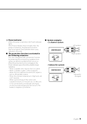
... light when the power is turned on , the Power indicator lights. Check whether there is any indication of trouble. ■ The protection function is activated in the following situations: This unit is turned on , the protection function may be short-circuited. • When a speaker output contacts ground. • When the unit malfunctions and a DC signal is sent to the battery's negative - When the protection function is not connected to a metal part...
... light when the power is turned on , the Power indicator lights. Check whether there is any indication of trouble. ■ The protection function is activated in the following situations: This unit is turned on , the protection function may be short-circuited. • When a speaker output contacts ground. • When the unit malfunctions and a DC signal is sent to the battery's negative - When the protection function is not connected to a metal part...
Instruction Manual
Page 6
...; The surface temperature of the amplifier will not come into contact with driving, In a location that gets wet, In a dusty location, In a place that gets hot, In a place that gets direct sunlight, In a location that electrical equipment such as a gasoline tank, brake pipe, or wiring harness, and be damaged. • Install this unit in a location which it may be careful not...
...; The surface temperature of the amplifier will not come into contact with driving, In a location that gets wet, In a dusty location, In a place that gets hot, In a place that gets direct sunlight, In a location that electrical equipment such as a gasoline tank, brake pipe, or wiring harness, and be damaged. • Install this unit in a location which it may be careful not...

Instruction Manual
Page 7
... instruction manual well to select the proper setting and connection. 1. Install the unit in the wiring, connect a fusible link or breaker nearby the battery's positive terminal. 2CAUTION • If sound is not output normally, immediately turn power off and check connections. • Be sure to turn the power off before changing the setting of any switch. • If the fuse blows, check wires for shorts, then replace the fuse with one of the units. 4. Connect the speaker wires. 5. Connect...
... instruction manual well to select the proper setting and connection. 1. Install the unit in the wiring, connect a fusible link or breaker nearby the battery's positive terminal. 2CAUTION • If sound is not output normally, immediately turn power off and check connections. • Be sure to turn the power off before changing the setting of any switch. • If the fuse blows, check wires for shorts, then replace the fuse with one of the units. 4. Connect the speaker wires. 5. Connect...
Instruction Manual
Page 8
Connection ■ RCA cable or Speaker level input connection (RCA cable Connections) RCA cable* CENTER UNIT (CD receiver, etc.) Left input Right input (Speaker level input Connections) Cable Color of the connector Left White White/Black Right Gray Gray/Black Power control wire (Blue/ White) Speaker level input cable Genuine-accessory car stereo (No line output center unit etc.) Car fuse box Battery ACC 8 English
Connection ■ RCA cable or Speaker level input connection (RCA cable Connections) RCA cable* CENTER UNIT (CD receiver, etc.) Left input Right input (Speaker level input Connections) Cable Color of the connector Left White White/Black Right Gray Gray/Black Power control wire (Blue/ White) Speaker level input cable Genuine-accessory car stereo (No line output center unit etc.) Car fuse box Battery ACC 8 English
Instruction Manual
Page 9
■ Speaker wire connection (Stereo Connections) Lead terminal* (Bridged Connections) 25 * Commercially available parts Left speaker Right speaker Speaker (Bridged) 25 ■ Power wire connection 25 Terminal cover Power control wire Battery wire* Ground wire* Protective Fuse* Battery Lead terminal* English 9
■ Speaker wire connection (Stereo Connections) Lead terminal* (Bridged Connections) 25 * Commercially available parts Left speaker Right speaker Speaker (Bridged) 25 ■ Power wire connection 25 Terminal cover Power control wire Battery wire* Ground wire* Protective Fuse* Battery Lead terminal* English 9

Instruction Manual
Page 10
Troubleshooting Guide What might appear to be a malfunction in the car body. is too • The input sensitivity adjusting control • Adjust the control correctly referring small (or too large). The output level is not set improperly. • Set switches properly by a screw • Connect the speaker wire again so in your unit may just be the result of the short, replace the fuse. that it is distorted.) wrong + /-polarity...
Troubleshooting Guide What might appear to be a malfunction in the car body. is too • The input sensitivity adjusting control • Adjust the control correctly referring small (or too large). The output level is not set improperly. • Set switches properly by a screw • Connect the speaker wire again so in your unit may just be the result of the short, replace the fuse. that it is distorted.) wrong + /-polarity...
Instruction Manual
Page 11
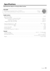
... dBA Audio Section Max Power Output ...350 W Rated Power Output Normal (4 Ω) (20 Hz - 20 kHz, 0.08 % THD)...55 W × 2 Normal (4 Ω) (DIN : 45324 , +B = 14.4V) ...55 W × 2 Normal (2 Ω) (1 kHz, 0.8 % THD)...75 W × 2 Bridged (4 Ω) (1 kHz, 0.8 % THD)...150 W × 1 Frequency Response (+0, -3 dB) ...5 Hz - 50 kHz Sensitivity (rated output) (MAX.) ...0.2 V Sensitivity (rated output) (MIN.) ...5.0 V Signal to change without notice. Specifications Specifications...
... dBA Audio Section Max Power Output ...350 W Rated Power Output Normal (4 Ω) (20 Hz - 20 kHz, 0.08 % THD)...55 W × 2 Normal (4 Ω) (DIN : 45324 , +B = 14.4V) ...55 W × 2 Normal (2 Ω) (1 kHz, 0.8 % THD)...75 W × 2 Bridged (4 Ω) (1 kHz, 0.8 % THD)...150 W × 1 Frequency Response (+0, -3 dB) ...5 Hz - 50 kHz Sensitivity (rated output) (MAX.) ...0.2 V Sensitivity (rated output) (MIN.) ...5.0 V Signal to change without notice. Specifications Specifications...

User Manual
Page 2
... cover (Power terminal) Speaker level input cable External Number of View Items 4 1 1 NOTE • If you experience problems during use because the surface of the unit. • Do not install the unit in the ACC ON position without turning the engine ON, it after starting the engine. They can scratch the surface of water splashing. • When replacing a fuse, only use automotive-grade wires or other wires with...
... cover (Power terminal) Speaker level input cable External Number of View Items 4 1 1 NOTE • If you experience problems during use because the surface of the unit. • Do not install the unit in the ACC ON position without turning the engine ON, it after starting the engine. They can scratch the surface of water splashing. • When replacing a fuse, only use automotive-grade wires or other wires with...

User Manual
Page 3
... heard from the battery. Use of speakers having input power ratings that are going to be used , use a power supply wiring wire and protective fuse of greater current-handling capacity than the maximum output power (in the power cord near the battery. terminal. When more than one set of speakers are going to install a protective fuse in Watts) of the car chassis that are less than the output power of the amplifier will cause smoke to...
... heard from the battery. Use of speakers having input power ratings that are going to be used , use a power supply wiring wire and protective fuse of greater current-handling capacity than the maximum output power (in the power cord near the battery. terminal. When more than one set of speakers are going to install a protective fuse in Watts) of the car chassis that are less than the output power of the amplifier will cause smoke to...

User Manual
Page 4
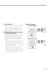
Use the diagram on the right as a stereo amplifier, stereo connections are cut.) The speaker output is automatically switched to monaural (L+R). 2 INPUT SENSITIVITY control Set this connection, shock noise may result. Be sure to connect it with this may cause malfunction or damage. • Connect the power control lead to a power supply which can be turned ON/OFF by the ignition key switch (ACC line). NOTE For the pre-output level or the...
Use the diagram on the right as a stereo amplifier, stereo connections are cut.) The speaker output is automatically switched to monaural (L+R). 2 INPUT SENSITIVITY control Set this connection, shock noise may result. Be sure to connect it with this may cause malfunction or damage. • Connect the power control lead to a power supply which can be turned ON/OFF by the ignition key switch (ACC line). NOTE For the pre-output level or the...
User Manual
Page 5
... protection function is high and unit won't operate. • When a ground wire of trouble. ■ The protection function is activated in the following situations: This unit is equipped with a protection function for protecting this unit is not connected to a metal part serving as an electrical ground passing electricity to the speaker output. • When the internal temperature is triggered, the Power indicator goes off and the amplifier stops operating. • When a speaker wire...
... protection function is high and unit won't operate. • When a ground wire of trouble. ■ The protection function is activated in the following situations: This unit is equipped with a protection function for protecting this unit is not connected to a metal part serving as an electrical ground passing electricity to the speaker output. • When the internal temperature is triggered, the Power indicator goes off and the amplifier stops operating. • When a speaker wire...

User Manual
Page 6
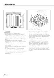
..., rear tray, or air bag safety parts. • The installation to the vehicle should securely fasten the unit to heat will not come into contact with driving, In a location that gets wet, In a dusty location, In a place that gets hot, In a place that gets direct sunlight, In a location that electrical equipment such as a gasoline tank, brake pipe, or wiring harness, and...
..., rear tray, or air bag safety parts. • The installation to the vehicle should securely fasten the unit to heat will not come into contact with driving, In a location that gets wet, In a dusty location, In a place that gets hot, In a place that gets direct sunlight, In a location that electrical equipment such as a gasoline tank, brake pipe, or wiring harness, and...

User Manual
Page 7
... output wires of the battery to appropriate speaker connectors separately. Connect the negative - English 7 Connect the speaker wires. 5. Connect the power wire, power control wire and grounding wire following this unit to select the proper setting and connection. 1. Sharing the negative wire of the speaker or grounding speaker wires to the metal body of the car can cause this order. 6. ■ Installation procedure Since there are large variety of settings and connections possible according to applications, read the instruction manual...
... output wires of the battery to appropriate speaker connectors separately. Connect the negative - English 7 Connect the speaker wires. 5. Connect the power wire, power control wire and grounding wire following this unit to select the proper setting and connection. 1. Sharing the negative wire of the speaker or grounding speaker wires to the metal body of the car can cause this order. 6. ■ Installation procedure Since there are large variety of settings and connections possible according to applications, read the instruction manual...

User Manual
Page 8
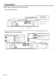
Connection ■ RCA cable or Speaker level input connection (RCA cable Connections) RCA cable* CENTER UNIT (CD receiver, etc.) Left input Right input (Speaker level input Connections) Cable Color of the connector Left White White/Black Right Gray Gray/Black Power control wire (Blue/ White) Speaker level input cable Genuine-accessory car stereo (No line output center unit etc.) Car fuse box Battery ACC 8 English
Connection ■ RCA cable or Speaker level input connection (RCA cable Connections) RCA cable* CENTER UNIT (CD receiver, etc.) Left input Right input (Speaker level input Connections) Cable Color of the connector Left White White/Black Right Gray Gray/Black Power control wire (Blue/ White) Speaker level input cable Genuine-accessory car stereo (No line output center unit etc.) Car fuse box Battery ACC 8 English

User Manual
Page 9
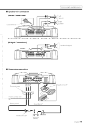
■ Speaker wire connection (Stereo Connections) Lead terminal* (Bridged Connections) 25 * Commercially available parts Left speaker Right speaker Speaker (Bridged) 25 ■ Power wire connection 25 Terminal cover Power control wire Battery wire* Ground wire* Protective Fuse* Battery Lead terminal* English 9
■ Speaker wire connection (Stereo Connections) Lead terminal* (Bridged Connections) 25 * Commercially available parts Left speaker Right speaker Speaker (Bridged) 25 ■ Power wire connection 25 Terminal cover Power control wire Battery wire* Ground wire* Protective Fuse* Battery Lead terminal* English 9

User Manual
Page 10
... check the following table for possible problems. PROBLEM POSSIBLE CAUSE SOLUTION No sound. • Input (or output) cables are connected with • Connect them properly checking the (The sound is not set improperly. • Set switches properly by referring to . • Volume is too high. • Replace the fuse and use lower volume. • The speaker cord is too • The input sensitivity adjusting control • Adjust the control correctly referring small (or too...
... check the following table for possible problems. PROBLEM POSSIBLE CAUSE SOLUTION No sound. • Input (or output) cables are connected with • Connect them properly checking the (The sound is not set improperly. • Set switches properly by referring to . • Volume is too high. • Replace the fuse and use lower volume. • The speaker cord is too • The input sensitivity adjusting control • Adjust the control correctly referring small (or too...


