
User Manual
Page 3
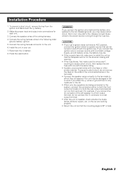
... connect the + connector of the wiring harness. 4. Make the proper input and output wire connections for each unit. 3. Connect the speaker wires of the left speaker to the power source running through the fuse box. 2CAUTION • If your car. 7. Install the unit in the following order: ground, battery, ignition. 5. Always connect those wires to a front output terminal, do not mix front and rear). If you share the - connector to both the rear output terminals (do not connect the - battery...
... connect the + connector of the wiring harness. 4. Make the proper input and output wire connections for each unit. 3. Connect the speaker wires of the left speaker to the power source running through the fuse box. 2CAUTION • If your car. 7. Install the unit in the following order: ground, battery, ignition. 5. Always connect those wires to a front output terminal, do not mix front and rear). If you share the - connector to both the rear output terminals (do not connect the - battery...
User Manual
Page 4
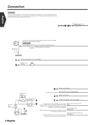
... detection switch harness using , Motor antenna control wire connect either to the control terminal of the motor (Blue) antenna, or to the power terminal for the booster amplifier of safety, be sure to the power source running through the fuse box. PRK SW Parking sensor wire (Green) C Ground wire (Black) - (To car chassis) Battery wire ( 5A ) B (Yellow) FM/AM antenna input Ignition key switch Car fuse box (Main fuse) ACC A B Car fuse box -+ C + Battery B Battery wire (Yellow) Dimmer control wire (Orange/White) To car light control switch A Ignition wire...
... detection switch harness using , Motor antenna control wire connect either to the control terminal of the motor (Blue) antenna, or to the power terminal for the booster amplifier of safety, be sure to the power source running through the fuse box. PRK SW Parking sensor wire (Green) C Ground wire (Black) - (To car chassis) Battery wire ( 5A ) B (Yellow) FM/AM antenna input Ignition key switch Car fuse box (Main fuse) ACC A B Car fuse box -+ C + Battery B Battery wire (Yellow) Dimmer control wire (Orange/White) To car light control switch A Ignition wire...
User Manual 1
Page 2
... Basic Operations of Remote Controller 12 Switch Screen Mode 14 Control during DVD Video or Video CD Playback 16 • Displaying the DVD/VCD Playback screen • Displaying the Easy Control Panel • Displaying the DVD/VCD Control screen • DVD Disc Menu • VCD Zoom Control • Information Display • Direct Search Tuner Control 22 • Displaying the Easy Control Panel • Displaying the Tuner Control screen • Displaying the Tuner Menu screen • Seek Mode • Auto Memory • Manual Memory • Preset Select • Set Station Name...
... Basic Operations of Remote Controller 12 Switch Screen Mode 14 Control during DVD Video or Video CD Playback 16 • Displaying the DVD/VCD Playback screen • Displaying the Easy Control Panel • Displaying the DVD/VCD Control screen • DVD Disc Menu • VCD Zoom Control • Information Display • Direct Search Tuner Control 22 • Displaying the Easy Control Panel • Displaying the Tuner Control screen • Displaying the Tuner Menu screen • Seek Mode • Auto Memory • Manual Memory • Preset Select • Set Station Name...
User Manual 1
Page 3
... Effect screen Position 76 • Displaying the Position screen Hands-Free Unit Control 78 GSM control 78 • Displaying the Control screen • When called • When dialing • Calling by Phone Book • Addition to Phone Book • Editing the Phone Book • Quick Dialing • Hand Free Setup • Reading the SMS (Short Message Service) messages • Creating an SMS (Short Message Service) message Glossary 86 Troubleshooting Guide 87 Specifications 92...
... Effect screen Position 76 • Displaying the Position screen Hands-Free Unit Control 78 GSM control 78 • Displaying the Control screen • When called • When dialing • Calling by Phone Book • Addition to Phone Book • Editing the Phone Book • Quick Dialing • Hand Free Setup • Reading the SMS (Short Message Service) messages • Creating an SMS (Short Message Service) message Glossary 86 Troubleshooting Guide 87 Specifications 92...
User Manual 1
Page 4
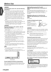
... result in damage to the main unit. • You cannot view video pictures whilst the vehicle is securely installed. The liquid crystal fluid may be dangerous to your Kenwood dealer. Reset button Screen brightness during collisions and other jolts. • When extending the ignition, battery or ground wires, make sure to use in operation checking, and their service life may fly out of place...
... result in damage to the main unit. • You cannot view video pictures whilst the vehicle is securely installed. The liquid crystal fluid may be dangerous to your Kenwood dealer. Reset button Screen brightness during collisions and other jolts. • When extending the ignition, battery or ground wires, make sure to use in operation checking, and their service life may fly out of place...
User Manual 1
Page 7
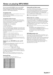
...instruction manual of Codes. The media reproducible on this , the order in which have the MP3/WMA extension. • Do not attempt to be played may not be possible when portions of the functions of Windows Media Player 9 or higher are used for folder name: 64 • Maximum number of characters used . Play mode...entered with characters not on the medium. Settings for Folder Select, files and folders are limited. Entering ID3 tag The Displayable ID3 tag is loaded, the unit checks all the data on the code list may be displayed correctly depending on your CD writer to ...
...instruction manual of Codes. The media reproducible on this , the order in which have the MP3/WMA extension. • Do not attempt to be played may not be possible when portions of the functions of Windows Media Player 9 or higher are used for folder name: 64 • Maximum number of characters used . Play mode...entered with characters not on the medium. Settings for Folder Select, files and folders are limited. Entering ID3 tag The Displayable ID3 tag is loaded, the unit checks all the data on the code list may be displayed correctly depending on your CD writer to ...
User Manual 1
Page 23
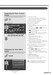
... to 6 buttons and Function buttons to the AM band. For memory of broadcasting stations, see (see page 24) or (see page 24 for the ) y Selects the Program Service Name, or Radio Text mode for text display. (Only when receiving the FM broadcast) u Scrolls the display text. English 23 q Tunes in a station using various functions. Seek Mode Indicator a Memory Number Display s Selects options from memory. d Returns to change the frequency switching. Displaying the Tuner Control screen You can tune in a station. Tuner Control screen 5 TUNER Audio 6 M e n u 5 Set Up 8 11...
... to 6 buttons and Function buttons to the AM band. For memory of broadcasting stations, see (see page 24) or (see page 24 for the ) y Selects the Program Service Name, or Radio Text mode for text display. (Only when receiving the FM broadcast) u Scrolls the display text. English 23 q Tunes in a station using various functions. Seek Mode Indicator a Memory Number Display s Selects options from memory. d Returns to change the frequency switching. Displaying the Tuner Control screen You can tune in a station. Tuner Control screen 5 TUNER Audio 6 M e n u 5 Set Up 8 11...
User Manual 1
Page 26
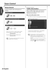
... DSP unit (optional accessory) is automatically remembered, and the next time it switches to the traffic information and it 's automatically the remembered volume. When you do not operate within 10 seconds. English Tuner Control Direct Search Tunes in a station when its frequency is displayed automatically. The Traffic Information screen appears automatically. Function of traffic information the adjusted volume is connected, the volume will be preset by pressing the button for...
... DSP unit (optional accessory) is automatically remembered, and the next time it switches to the traffic information and it 's automatically the remembered volume. When you do not operate within 10 seconds. English Tuner Control Direct Search Tunes in a station when its frequency is displayed automatically. The Traffic Information screen appears automatically. Function of traffic information the adjusted volume is connected, the volume will be preset by pressing the button for...
User Manual 1
Page 47
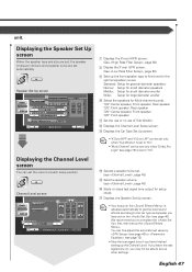
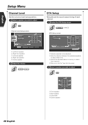
... fine-tune for Multi-channel sounds. u Displays the Speaker Set Up screen. • Your setup on the is set up the Channel Level. English 47 Channel Level screen 14 Menu Audio Set Up 16 Te s t SRC 15 Ce n t e r 15 + 1 0 dB 17 Chann e l Level 7 Displays the X'over (HPF) screen. (See , page 50) 8 Display the X'over (LPF) screen. (See , page 50) 9 Sets up other settings. "3/2": Center speaker, Front speaker, Rear speaker "2/2": Front speaker, Rear speaker "3/0": Center speaker, Front speaker "2/0": Front speaker q Set the use or no use of Sub Woofer...
... fine-tune for Multi-channel sounds. u Displays the Speaker Set Up screen. • Your setup on the is set up the Channel Level. English 47 Channel Level screen 14 Menu Audio Set Up 16 Te s t SRC 15 Ce n t e r 15 + 1 0 dB 17 Chann e l Level 7 Displays the X'over (HPF) screen. (See , page 50) 8 Display the X'over (LPF) screen. (See , page 50) 9 Sets up other settings. "3/2": Center speaker, Front speaker, Rear speaker "2/2": Front speaker, Rear speaker "3/0": Center speaker, Front speaker "2/0": Front speaker q Set the use or no use of Sub Woofer...
User Manual 1
Page 48
...1 Select a speaker you wish to adjust Channel Level setup screen Audio Menu 1 Set Up Te s t SRC 3 Ce n t e r + 1 0 dB 5 2 4 Chann e l Level 1 Left front speaker 2 Right front speaker 3 Left rear speaker 4 Right rear speaker 5 Center speaker 2 Adjust the volume DTA Setup Manually set the sound output timing of each channel. 1 Display the DTA Setup screen D TA (P46 5) DTA Setup screen D TA 1 3 Pr e s e t 2 Front 1 m 2 4 Return 1 Selects a speaker to be adjusted. 2 Sets the distance between the selected speakers to adjust delay time. 3 Stores the adjusted status in memory or...
...1 Select a speaker you wish to adjust Channel Level setup screen Audio Menu 1 Set Up Te s t SRC 3 Ce n t e r + 1 0 dB 5 2 4 Chann e l Level 1 Left front speaker 2 Right front speaker 3 Left rear speaker 4 Right rear speaker 5 Center speaker 2 Adjust the volume DTA Setup Manually set the sound output timing of each channel. 1 Display the DTA Setup screen D TA (P46 5) DTA Setup screen D TA 1 3 Pr e s e t 2 Front 1 m 2 4 Return 1 Selects a speaker to be adjusted. 2 Sets the distance between the selected speakers to adjust delay time. 3 Stores the adjusted status in memory or...
User Manual 1
Page 55
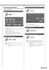
... a code number. 2 Cancels the current setup and returns to the DVD SETUP 2 screen. 3 Clears the code number. 4 Displays the present parental lock level. 5 Determines the code number and displays the Parental Level Setup screen. 2 Enter the code number 0-9 • The number you enter first is set as your code number. • You can clear the password by pressing the Reset button. 1 Le v e l 5 1 2 Return 1 Sets a parental level. 2 Returns to the DVD SETUP 2 screen. 4 Set a parental level 5 Enter the parental level setup Return • If a disc has...
... a code number. 2 Cancels the current setup and returns to the DVD SETUP 2 screen. 3 Clears the code number. 4 Displays the present parental lock level. 5 Determines the code number and displays the Parental Level Setup screen. 2 Enter the code number 0-9 • The number you enter first is set as your code number. • You can clear the password by pressing the Reset button. 1 Le v e l 5 1 2 Return 1 Sets a parental level. 2 Returns to the DVD SETUP 2 screen. 4 Set a parental level 5 Enter the parental level setup Return • If a disc has...
User Manual 1
Page 63
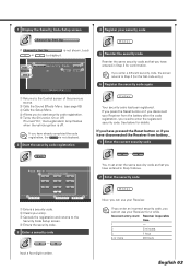
... Your security code has been registered. 1 Display the Security Code Setup screen 4 Register your security code Security Set Up Enter If Secur i t y Set Up is not shown, touch or to display it. 3 Menu Audio 2 Set Up SRC 1 Sec u r i t y Code 5 SI On 4 Set 5 Off Secur i t y 1 Returns to the Control screen of the previous source. 2 Calls the Sound Effects Menu. (see page 68) 3 Calls the Setup Menu. 4 Allows you cannot use your Receiver. If turned "On...
... Your security code has been registered. 1 Display the Security Code Setup screen 4 Register your security code Security Set Up Enter If Secur i t y Set Up is not shown, touch or to display it. 3 Menu Audio 2 Set Up SRC 1 Sec u r i t y Code 5 SI On 4 Set 5 Off Secur i t y 1 Returns to the Control screen of the previous source. 2 Calls the Sound Effects Menu. (see page 68) 3 Calls the Setup Menu. 4 Allows you cannot use your Receiver. If turned "On...
User Manual 1
Page 66
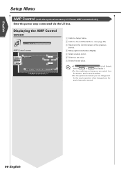
...Setup Menu AMP Control (with the optional accessory LX Power AMP connected only) Sets the power amp connected via the LX bus. Displaying the AMP Control screen AMP Ctrl AMP Control screen 1 Menu Audio 2 Set Up SRC 3 5 6 5 4 A M P 1 VO LT 1 4 . 4 V AMP Control 6 7 Set 1 Calls the Setup Menu. 2 Calls the Sound Effects Menu. (see page 68) 3 Returns to the Control screen of the previous source. 4 Setup option and value display 5 Select a setup option. 6 Selects a set value. 7 Enters the set value. • If A M P C t r l touch or is not shown, to display it. • For the model...
...Setup Menu AMP Control (with the optional accessory LX Power AMP connected only) Sets the power amp connected via the LX bus. Displaying the AMP Control screen AMP Ctrl AMP Control screen 1 Menu Audio 2 Set Up SRC 3 5 6 5 4 A M P 1 VO LT 1 4 . 4 V AMP Control 6 7 Set 1 Calls the Setup Menu. 2 Calls the Sound Effects Menu. (see page 68) 3 Returns to the Control screen of the previous source. 4 Setup option and value display 5 Select a setup option. 6 Selects a set value. 7 Enters the set value. • If A M P C t r l touch or is not shown, to display it. • For the model...
User Manual 1
Page 69
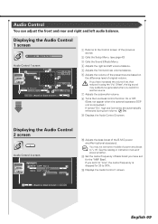
Displaying the Audio Control 1 screen Au d i o Co n t r o l Audio Control 1 screen Audio Set Up 3 Menu 2 4 L F r o n5t F FAD F 1 2 BAL R 1 2 4 R SRC 1 Vo l . O f f s e t 6 -15 SUB -1 5 R R e a r5 7 7 6 8 LOUD O f f Aud i o Con t r o l 1 9 1 Returns to another source. 7 Adjusts the subwoofer volume. 8 Turns the Loudness control function On or Off. (Does not appear when the optional accessory DSP unit is dropped for the "AMP Bass". Offset", the big sound may not set some models of power amp boost to 30%. You may suddenly be generated when...
Displaying the Audio Control 1 screen Au d i o Co n t r o l Audio Control 1 screen Audio Set Up 3 Menu 2 4 L F r o n5t F FAD F 1 2 BAL R 1 2 4 R SRC 1 Vo l . O f f s e t 6 -15 SUB -1 5 R R e a r5 7 7 6 8 LOUD O f f Aud i o Con t r o l 1 9 1 Returns to another source. 7 Adjusts the subwoofer volume. 8 Turns the Loudness control function On or Off. (Does not appear when the optional accessory DSP unit is dropped for the "AMP Bass". Offset", the big sound may not set some models of power amp boost to 30%. You may suddenly be generated when...
User Manual 1
Page 70
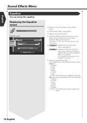
..." • "Jazz" • "User" (when the tone curve (page 71) is set up) KBS (with the optional accessory DSP unit connected) You can adjust the value set for the Tone Curve setup. (Does not appear when the optional accessory DSP unit is set up the equalizer. English Sound Effects Menu Equalizer You can set up) 70 English Displaying the Equalizer screen Equa l i z er Equalizer screen Audio Set Up SRC 3 Menu 2 6 System Q Natural...
..." • "Jazz" • "User" (when the tone curve (page 71) is set up) KBS (with the optional accessory DSP unit connected) You can adjust the value set for the Tone Curve setup. (Does not appear when the optional accessory DSP unit is set up the equalizer. English Sound Effects Menu Equalizer You can set up) 70 English Displaying the Equalizer screen Equa l i z er Equalizer screen Audio Set Up SRC 3 Menu 2 6 System Q Natural...
User Manual 1
Page 72
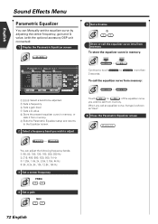
... DSP unit connected) 1 Display the Parametric Equalizer screen P-EQ P aramet r i c Equ a l i z e r 1 2 3 4 Band1 Band2 Band3 Band4 Hz 800 dB +12 3. 0 0 Hz 800 dB +12 3. 0 0 KH z 2.25 dB +12 3. 0 0 KHz 5 FREQ 5 2.25 dB 6 G a i n 6 +12 7 Q 7 3. 0 0 P1 P2 P3 8 Re t u r n 9 1234 Select a band to be adjusted. 5 Sets a frequency. 6 Sets a gain level. 7 Sets a Q value. 8 Store the present equalizer curve in memory: P1 - To call the equalizer curve into/from memory: P1...
... DSP unit connected) 1 Display the Parametric Equalizer screen P-EQ P aramet r i c Equ a l i z e r 1 2 3 4 Band1 Band2 Band3 Band4 Hz 800 dB +12 3. 0 0 Hz 800 dB +12 3. 0 0 KH z 2.25 dB +12 3. 0 0 KHz 5 FREQ 5 2.25 dB 6 G a i n 6 +12 7 Q 7 3. 0 0 P1 P2 P3 8 Re t u r n 9 1234 Select a band to be adjusted. 5 Sets a frequency. 6 Sets a gain level. 7 Sets a Q value. 8 Store the present equalizer curve in memory: P1 - To call the equalizer curve into/from memory: P1...
User Manual 1
Page 87
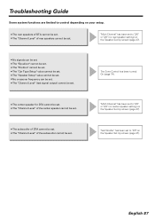
... be set . "Multi Channel" has been set to "2/0" or "2/2" (no rear speaker setting) on the Speaker Set Up screen (page 47). ¶ No signals can be set. ¶ The "Equalizer" cannot be set. ¶ The "Position" cannot be set. ¶ The "Car Type Setup" value cannot be set. ¶ The "Speaker Setup" value cannot be set. ¶ No crossover frequency can be set. ¶ The "Channel Level" (test signal output) cannot be set . English 87 "Sub...
... be set . "Multi Channel" has been set to "2/0" or "2/2" (no rear speaker setting) on the Speaker Set Up screen (page 47). ¶ No signals can be set. ¶ The "Equalizer" cannot be set. ¶ The "Position" cannot be set. ¶ The "Car Type Setup" value cannot be set. ¶ The "Speaker Setup" value cannot be set. ¶ No crossover frequency can be set. ¶ The "Channel Level" (test signal output) cannot be set . English 87 "Sub...
User Manual 1
Page 88
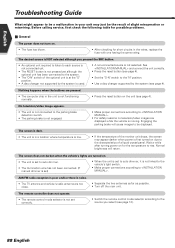
... radio reception is poor and/or there is not linked to the vehicle's light switch. • Make proper connections according to . The desired source is NOT selected although you select (see page 4). • Set the "O-N" switch to the "N" position. • Use a disc changer supported by the system is used. • A non-connected source is not functioning normally. • Press the reset button on . • The unit is set to auto dimmer. • The illumination wire...
... radio reception is poor and/or there is not linked to the vehicle's light switch. • Make proper connections according to . The desired source is NOT selected although you select (see page 4). • Set the "O-N" switch to the "N" position. • Use a disc changer supported by the system is used. • A non-connected source is not functioning normally. • Press the reset button on . • The unit is set to auto dimmer. • The illumination wire...
User Manual 1
Page 89
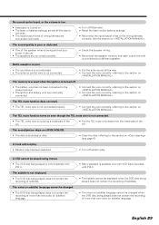
... play has been selected. • Turn off Attenuator. • Reset the fader and/or balance settings. • Reconnect the input/output wires or the wiring harness correctly. The sound/picture skips on a DVD/VCD/CD. • The disc is scratched or dirty. • Clean the disc, referring to the section on (see page 6). The TEL mute function does not work. • The TEL mute wire is not connected properly. • Connect the wire...
... play has been selected. • Turn off Attenuator. • Reset the fader and/or balance settings. • Reconnect the input/output wires or the wiring harness correctly. The sound/picture skips on a DVD/VCD/CD. • The disc is scratched or dirty. • Clean the disc, referring to the section on (see page 6). The TEL mute function does not work. • The TEL mute wire is not connected properly. • Connect the wire...
User Manual 1
Page 90
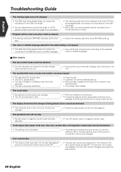
... the viewing restriction level (RATING) setting. Playback will not play. • Random play or magazine random play start even after a title is selected. • A viewing restriction (RATING) has been set for the specified disc. • Try another one viewing angle may be selected. • No wire has been connected to the disc changer input terminal on the unit. • Connect the wire to the disc changer input terminal on the unit (see page 4). The display...
... the viewing restriction level (RATING) setting. Playback will not play. • Random play or magazine random play start even after a title is selected. • A viewing restriction (RATING) has been set for the specified disc. • Try another one viewing angle may be selected. • No wire has been connected to the disc changer input terminal on the unit. • Connect the wire to the disc changer input terminal on the unit (see page 4). The display...


