
Operation Manual
Page 1
Familiarity with installation and operation procedures will help you call upon your new Universal Camera. For your Kenwood product at www.Kenwoodusa.com © 2014 JVC KENWOOD Corporation LYT2720-001A (W) Model CMOS-320/CMOS-220 Serial number US Residence Only Register Online Register your records Record the serial number, found on the back of the unit...
Familiarity with installation and operation procedures will help you call upon your new Universal Camera. For your Kenwood product at www.Kenwoodusa.com © 2014 JVC KENWOOD Corporation LYT2720-001A (W) Model CMOS-320/CMOS-220 Serial number US Residence Only Register Online Register your records Record the serial number, found on the back of the unit...

Operation Manual
Page 4
... Adjust the camera bracket shape so that the "KENWOOD" logo appears at the top. Installation position (lower) The CMOS-320 should be attached. 3 Loosen the camera bracket retaining screws. The CMOS-320 should be attached. Mount so that the "KENWOOD" logo appears at the top. Mount so that the "KENWOOD" logo appears at the top. 6 Fix the...
... Adjust the camera bracket shape so that the "KENWOOD" logo appears at the top. Installation position (lower) The CMOS-320 should be attached. 3 Loosen the camera bracket retaining screws. The CMOS-320 should be attached. Mount so that the "KENWOOD" logo appears at the top. Mount so that the "KENWOOD" logo appears at the top. 6 Fix the...

Operation Manual
Page 6
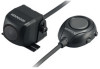
...633; When using the camera bracket clamping screw. For the ID setting, see "Camera ID Setting"(page 13) 6 | CMOS-320/CMOS-220 Do not touch the adhesive surface with a Kenwood navigation system, this switch unit is to attach the switch unit with your hand or peel and reattach an attached tape...with double-side adhesive tape. So you do not have to be detached. Camera bracket clamping screw (M3 x 8mm) Installing the Switch Unit (CMOS-320 only) 1 Clean the switch unit installation surface. Select one of them to be attached. 2 Attach double-side adhesive tape on which the ...
...633; When using the camera bracket clamping screw. For the ID setting, see "Camera ID Setting"(page 13) 6 | CMOS-320/CMOS-220 Do not touch the adhesive surface with a Kenwood navigation system, this switch unit is to attach the switch unit with your hand or peel and reattach an attached tape...with double-side adhesive tape. So you do not have to be detached. Camera bracket clamping screw (M3 x 8mm) Installing the Switch Unit (CMOS-320 only) 1 Clean the switch unit installation surface. Select one of them to be attached. 2 Attach double-side adhesive tape on which the ...

Operation Manual
Page 8
...camera) Connect to the external video input. Select the external video input to a Kenwood navigation system etc, (Control unit) equipped with the camera control function, use the provided control unit connection cord. System Connection (CMOS-320 only) • When connecting the camera to check the camera image. For ...as well on touch the control unit screen. • When using two CMOS-320 units (for the front and rear), it is not used in the system connection. Video cord To power supply 8 | CMOS-320/CMOS-220 This allows the control unit to switch the display view and adjust ...
...camera) Connect to the external video input. Select the external video input to a Kenwood navigation system etc, (Control unit) equipped with the camera control function, use the provided control unit connection cord. System Connection (CMOS-320 only) • When connecting the camera to check the camera image. For ...as well on touch the control unit screen. • When using two CMOS-320 units (for the front and rear), it is not used in the system connection. Video cord To power supply 8 | CMOS-320/CMOS-220 This allows the control unit to switch the display view and adjust ...

Operation Manual
Page 13
...ADJUSTMENT (Red Line Position Setting)". 2 Press the + or - For displaying the image, refer to the Kenwood car navigation system. 9 Turn on the monitor of the Kenwood navigation system. CMOS-320/CMOS-220 | 13 Refer to [Front Camera]. 1 Install the switch unit. Finishing the Camera Setting 5 After... setting, press the + or - Camera ID Setting When connecting a CMOS-320 as a front camera to a Kenwood navigation system equipped with the camera control function, it . 3 Press and hold the - button for the connection. 2 ...
...ADJUSTMENT (Red Line Position Setting)". 2 Press the + or - For displaying the image, refer to the Kenwood car navigation system. 9 Turn on the monitor of the Kenwood navigation system. CMOS-320/CMOS-220 | 13 Refer to [Front Camera]. 1 Install the switch unit. Finishing the Camera Setting 5 After... setting, press the + or - Camera ID Setting When connecting a CMOS-320 as a front camera to a Kenwood navigation system equipped with the camera control function, it . 3 Press and hold the - button for the connection. 2 ...

Operation Manual
Page 14
... display 4 kinds of camera images. 1 With an image displayed on the connected navigation system. 14 | CMOS-320/CMOS-220 Corner View The views seen from the viewpoint straight up above the vehicle. This allows the control unit to a Kenwood navigation system etc, (Control unit) equipped with the camera control function, use the provided control...
... display 4 kinds of camera images. 1 With an image displayed on the connected navigation system. 14 | CMOS-320/CMOS-220 Corner View The views seen from the viewpoint straight up above the vehicle. This allows the control unit to a Kenwood navigation system etc, (Control unit) equipped with the camera control function, use the provided control...


