Instruction Manual
Page 3
CD6112 TABLE OF CONTENTS Table of Contents i Introduction 1 Installation 2 Wiring Diagram 4 Front Panel Release 5 Operation 6 Tuner Operation 8 CD Player Operation 9 Remote Control 10 Care and Maintenance 11 Troubleshooting 12 Specifications 13 i
CD6112 TABLE OF CONTENTS Table of Contents i Introduction 1 Installation 2 Wiring Diagram 4 Front Panel Release 5 Operation 6 Tuner Operation 8 CD Player Operation 9 Remote Control 10 Care and Maintenance 11 Troubleshooting 12 Specifications 13 i
Instruction Manual
Page 6
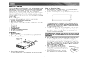
... application before purchasing to the dashboard. Remove Transport Screws TRANSPORT SCREWS HALF SLEEVE CD6112 MOSFET POWERED / LO/DX LOUD PS/AS DN UP 3. CAUTION: For proper operation of the CD player, the chassis must be mounted within this limitation. 4. Place the radio... Crimp connections • 18 gauge wire for power connections • 16-18 gauge speaker wire Preparation 1. CD6112 Using the Mounting Sleeve 1. Make sure the unit is mounted within 20° of horizontal. See "Wiring Diagram" on page 4.After completing the wiring connections, turn the unit on )....
... application before purchasing to the dashboard. Remove Transport Screws TRANSPORT SCREWS HALF SLEEVE CD6112 MOSFET POWERED / LO/DX LOUD PS/AS DN UP 3. CAUTION: For proper operation of the CD player, the chassis must be mounted within this limitation. 4. Place the radio... Crimp connections • 18 gauge wire for power connections • 16-18 gauge speaker wire Preparation 1. CD6112 Using the Mounting Sleeve 1. Make sure the unit is mounted within 20° of horizontal. See "Wiring Diagram" on page 4.After completing the wiring connections, turn the unit on )....
Instruction Manual
Page 8
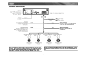
... (Front) Right Speaker (Front) Left Speaker (Rear) Right Speaker (Rear) NOTE: The amplifier in Ground Connect to existing radio wire or radio fuse. WIRING DIAGRAM CD6112 Antenna Connect the antenna plug from the existing antenna cable (some vehicles require an adaptor). NOTE: Only connect speakers rated in the load... Never combine (bridge) outputs for use with two speakers. Fuse (15 amp fast blow ATO) R (Red) L (White) Aux-in this wire is only designed for use with a load impedance less than 4 ohms could damage the unit. 4 If not used, tape bare end of...
... (Front) Right Speaker (Front) Left Speaker (Rear) Right Speaker (Rear) NOTE: The amplifier in Ground Connect to existing radio wire or radio fuse. WIRING DIAGRAM CD6112 Antenna Connect the antenna plug from the existing antenna cable (some vehicles require an adaptor). NOTE: Only connect speakers rated in the load... Never combine (bridge) outputs for use with two speakers. Fuse (15 amp fast blow ATO) R (Red) L (White) Aux-in this wire is only designed for use with a load impedance less than 4 ohms could damage the unit. 4 If not used, tape bare end of...


