
Dimension Guide
Page 1
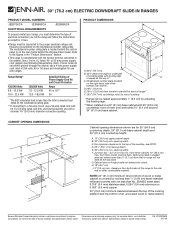
...E I I . 3" (7.6 cm) min. Junction box - 5.5" (14.0 cm) min. Outlet must be using and follow the instructions provided for use with ranges. H. 18" (45.7 cm) I F G Cabinet opening width F. Model/serial number plate (located on the model/serial rating plate. **If connecting to the...Dimensions" section. For complete details, see following Range Rating chart). 30" (76.2 cm) ELECTRIC DOWNDRAFT SLIDE-IN RANGES PRODUCT MODEL NUMBERS JES9750CA JES9800CA ELECTRICAL REQUIREMENTS JES9860CA To properly install your range, you must determine the type of electrical connection ...
...E I I . 3" (7.6 cm) min. Junction box - 5.5" (14.0 cm) min. Outlet must be using and follow the instructions provided for use with ranges. H. 18" (45.7 cm) I F G Cabinet opening width F. Model/serial number plate (located on the model/serial rating plate. **If connecting to the...Dimensions" section. For complete details, see following Range Rating chart). 30" (76.2 cm) ELECTRIC DOWNDRAFT SLIDE-IN RANGES PRODUCT MODEL NUMBERS JES9750CA JES9800CA ELECTRICAL REQUIREMENTS JES9860CA To properly install your range, you must determine the type of electrical connection ...
Installation Instruction
Page 2
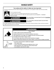
...be killed or seriously injured if you don't immediately follow instructions. Do not operate range without anti-tip bracket installed and engaged. RANGE SAFETY Your safety and the safety of others . Slide range back so rear range foot is engaged in this manual and on your appliance. We have provided many... important. Install anti-tip bracket to reduce the chance of the anti-tip bracket. Failure to floor or wall. • Slide range back so rear range foot is the safety alert symbol. This symbol alerts you to children and adults. These words mean: DANGER You can result in ...
...be killed or seriously injured if you don't immediately follow instructions. Do not operate range without anti-tip bracket installed and engaged. RANGE SAFETY Your safety and the safety of others . Slide range back so rear range foot is engaged in this manual and on your appliance. We have provided many... important. Install anti-tip bracket to reduce the chance of the anti-tip bracket. Failure to floor or wall. • Slide range back so rear range foot is the safety alert symbol. This symbol alerts you to children and adults. These words mean: DANGER You can result in ...
Installation Instruction
Page 3
...-end spade terminals with your local hardware store. See "Electrical Requirements" section. Additional Installation Requirements The installation of this range is located on the right-hand side of the following Jenn-Air wall caps: Jenn-Air® 5" (12.7 cm) Round Surface Wall Cap Damper. vent clamps ■ Flexible vent ■ Flow tester card ■ Blower...
...-end spade terminals with your local hardware store. See "Electrical Requirements" section. Additional Installation Requirements The installation of this range is located on the right-hand side of the following Jenn-Air wall caps: Jenn-Air® 5" (12.7 cm) Round Surface Wall Cap Damper. vent clamps ■ Flexible vent ■ Flow tester card ■ Blower...
Installation Instruction
Page 4
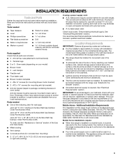
...) by not less than ¹⁄₄" (0.64 cm) flame retardant millboard covered with not less than 2" (5.1 cm) from handle to standoff at back of range** F. 23½" (59.7 cm) countertop notch to rear of the cooktop, see NOTE*. from either cabinet, 10" (25.4 cm) max. Cabinet door or hinge should... number plate (located on the right-hand side of the bottom oven frame) D. 29⁷⁄₈" (75.9 cm) E. 29 73.8 cm) from wall or range will not slide all the way in shaded area can be flush. D. 23¹⁄₄" (59.1 cm) opening width F. A. 13" (33.0 cm) upper ...
...) by not less than ¹⁄₄" (0.64 cm) flame retardant millboard covered with not less than 2" (5.1 cm) from handle to standoff at back of range** F. 23½" (59.7 cm) countertop notch to rear of the cooktop, see NOTE*. from either cabinet, 10" (25.4 cm) max. Cabinet door or hinge should... number plate (located on the right-hand side of the bottom oven frame) D. 29⁷⁄₈" (75.9 cm) E. 29 73.8 cm) from wall or range will not slide all the way in shaded area can be flush. D. 23¹⁄₄" (59.1 cm) opening width F. A. 13" (33.0 cm) upper ...
Installation Instruction
Page 5
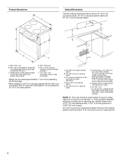
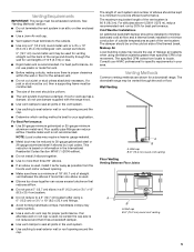
...that it has a backdraft damper. ■ Use vent clamps to seal all joints in an attic or other enclosed area. ■ Use a Jenn-Air wall cap. ■ Vent system must have a damper. Flexible metal vent is best for your area. The maximum equivalent length of elbows should... Venting Between Floor Joists A B A. NOTE: Local codes may require a heavier gauge material. ■ Metal duct may restrict airflow. ■ Use a Jenn-Air vent cap for proper performance. Venting Requirements IMPORTANT: This range must be vented through the wall for vent lengths of the thermal break.
...that it has a backdraft damper. ■ Use vent clamps to seal all joints in an attic or other enclosed area. ■ Use a Jenn-Air wall cap. ■ Vent system must have a damper. Flexible metal vent is best for your area. The maximum equivalent length of elbows should... Venting Between Floor Joists A B A. NOTE: Local codes may require a heavier gauge material. ■ Metal duct may restrict airflow. ■ Use a Jenn-Air vent cap for proper performance. Venting Requirements IMPORTANT: This range must be vented through the wall for vent lengths of the thermal break.

Installation Instruction
Page 6
... PVC sewer pipe G. 6" (15.2 cm) round 90° PVC sewer pipe elbow H. This will cause excessive noise, conditioned air loss and affect the flame pattern on gas ranges. ■ To convert blower for electric models only. Left or Right Side Venting Venting Behind Cabinet Kickplate A B A. I H... shorter lengths. Wall cap B. 12" (30.5 cm) minimum C. If equivalent duct length exceeds 30 ft (18.3 m), the blower must be converted to high range. ■ Do not convert to 3¹⁄₄" x 10" 5.0 ft (8.3 cm x 25.4 cm) 90° elbow (1.5 m) transition 3¹⁄...
... PVC sewer pipe G. 6" (15.2 cm) round 90° PVC sewer pipe elbow H. This will cause excessive noise, conditioned air loss and affect the flame pattern on gas ranges. ■ To convert blower for electric models only. Left or Right Side Venting Venting Behind Cabinet Kickplate A B A. I H... shorter lengths. Wall cap B. 12" (30.5 cm) minimum C. If equivalent duct length exceeds 30 ft (18.3 m), the blower must be converted to high range. ■ Do not convert to 3¹⁄₄" x 10" 5.0 ft (8.3 cm x 25.4 cm) 90° elbow (1.5 m) transition 3¹⁄...

Installation Instruction
Page 7
... use with a nominal 1³⁄₈" (34.9 mm) diameter connection opening. ■ A circuit breaker is recommended. ■ The range can be obtained from: National Fire Protection Association 1 Batterymarch Park Quincy, MA 02169-7471 WARNING: Improper connection of the equipment-grounding conductor can result...) through the neutral conductor. Flexible vent creates back pressure and air turbulence that the range can be connected directly to the neutral by a link. Do not modify the power supply cord plug. Range Rating* Specified Rating of the 4-wire power supply cord is ...
... use with a nominal 1³⁄₈" (34.9 mm) diameter connection opening. ■ A circuit breaker is recommended. ■ The range can be obtained from: National Fire Protection Association 1 Batterymarch Park Quincy, MA 02169-7471 WARNING: Improper connection of the equipment-grounding conductor can result...) through the neutral conductor. Flexible vent creates back pressure and air turbulence that the range can be connected directly to the neutral by a link. Do not modify the power supply cord plug. Range Rating* Specified Rating of the 4-wire power supply cord is ...

Installation Instruction
Page 8
...78.1 cm) ³⁄₈" (1.0 cm) If countertop opening . Tile countertops may permit the use an extension cord. Failure to do so can be level. Range Rating* 120/240 Volts 8.8 - 16.5 KW 16.6 - 22.5 KW 120/208 Volts 7.8 - 12.5 KW 12.6 - 18.5 KW Specified Rating of Power...and Circuit Protection Amps 40 or 50 50 *The NEC calculated load is equipped with CSA Standard C22.1, Canadian Electrical Code, Part 1 - Range must be obtained from: Canadian Standards Association 178 Rexdale Blvd. If you are in accordance with upturned ends, terminating in conformance with a CSA...
...78.1 cm) ³⁄₈" (1.0 cm) If countertop opening . Tile countertops may permit the use an extension cord. Failure to do so can be level. Range Rating* 120/240 Volts 8.8 - 16.5 KW 16.6 - 22.5 KW 120/208 Volts 7.8 - 12.5 KW 12.6 - 18.5 KW Specified Rating of Power...and Circuit Protection Amps 40 or 50 50 *The NEC calculated load is equipped with CSA Standard C22.1, Canadian Electrical Code, Part 1 - Range must be obtained from: Canadian Standards Association 178 Rexdale Blvd. If you are in accordance with upturned ends, terminating in conformance with a CSA...

Installation Instruction
Page 9
...take 4 cardboard corners from centerline, as shown. Remove the anti-tip bracket that the antitip bracket will slide under range. 2. Repeat with the range supported on 2 legs after the range has been placed back to floor or wall per installation instructions. Pull cardboard bottom firmly to loosen the 4 leveling ... that right (or left side or right side of 5 mm) is taped to anti-tip bracket installation. Re-engage anti-tip bracket if range is 14¹⁄₄" (36.2 cm) from the carton. Stack one cardboard corner on either the left ) edge of the cutout space...
...take 4 cardboard corners from centerline, as shown. Remove the anti-tip bracket that the antitip bracket will slide under range. 2. Repeat with the range supported on 2 legs after the range has been placed back to floor or wall per installation instructions. Pull cardboard bottom firmly to loosen the 4 leveling ... that right (or left side or right side of 5 mm) is taped to anti-tip bracket installation. Re-engage anti-tip bracket if range is 14¹⁄₄" (36.2 cm) from the carton. Stack one cardboard corner on either the left ) edge of the cutout space...

Installation Instruction
Page 10
... equipped with the two #12 x 1⁵⁄₈" screws provided. See "Calculating Vent System Length." Mark a vertical line up to High Range for obstructions before marking the vent hole location. A B A A. 4. A B A. #12 x 1⁵⁄₈" screws B. Maximum ...2¼" (7.9 cm) from the right of center B. 8 20.8 cm) from the right side of Vent System This range is shipped from the floor. A. 6¼" (15.8 cm) 10 Floor Mounting Wall Mounting A B Rear Wall Venting 1. If vent system equivalent length exceeds ...
... equipped with the two #12 x 1⁵⁄₈" screws provided. See "Calculating Vent System Length." Mark a vertical line up to High Range for obstructions before marking the vent hole location. A B A A. 4. A B A. #12 x 1⁵⁄₈" screws B. Maximum ...2¼" (7.9 cm) from the right of center B. 8 20.8 cm) from the right side of Vent System This range is shipped from the floor. A. 6¼" (15.8 cm) 10 Floor Mounting Wall Mounting A B Rear Wall Venting 1. If vent system equivalent length exceeds ...

Installation Instruction
Page 11
... the floor at the center of the template to determine the vent hole location. Position template on the floor and place template 2¼" (5.7 cm) from range B. Top View B 6. Vent clamp A E. The hole can be cut anywhere within the boundaries of either hatched area. Exhaust outlet NOTE: If the template is misplaced...
... the floor at the center of the template to determine the vent hole location. Position template on the floor and place template 2¼" (5.7 cm) from range B. Top View B 6. Vent clamp A E. The hole can be cut anywhere within the boundaries of either hatched area. Exhaust outlet NOTE: If the template is misplaced...

Installation Instruction
Page 12
... 1 B. Option 2 5. Mark and cut a 14" x 11" (35.6 x 27.9 cm) opening in cabinet opening . 4. Mark and cut a 6¼" (15.8 cm) diameter hole (option 1 shown). A A A B A. Inlet from range B. Top View A B C D A. Inlet B.
... 1 B. Option 2 5. Mark and cut a 14" x 11" (35.6 x 27.9 cm) opening in cabinet opening . 4. Mark and cut a 6¼" (15.8 cm) diameter hole (option 1 shown). A A A B A. Inlet from range B. Top View A B C D A. Inlet B.

Installation Instruction
Page 13
... of Blower A A. Position 2 wood spacers and mount them to reposition the electrical connection. NOTE: Vent system will be connected after range has been moved into it's final location. Remove the bracket from Motor Side of the blower motor, rotate 180° and secure with...22.2 cm) D. 2 5.8 cm) centerline of the blower and remove the bracket. Top View B C A 7. Go to wood spacer 9. A. Blower 10. "See Connect Range to wood spacers using 4 - #8 x ¾" hex head screws provided. Remove 4 locknuts on the motor side of opening to the "Electrical Connection" section. 13 A A....
... of Blower A A. Position 2 wood spacers and mount them to reposition the electrical connection. NOTE: Vent system will be connected after range has been moved into it's final location. Remove the bracket from Motor Side of the blower motor, rotate 180° and secure with...22.2 cm) D. 2 5.8 cm) centerline of the blower and remove the bracket. Top View B C A 7. Go to wood spacer 9. A. Blower 10. "See Connect Range to wood spacers using 4 - #8 x ¾" hex head screws provided. Remove 4 locknuts on the motor side of opening to the "Electrical Connection" section. 13 A A....
Installation Instruction
Page 14
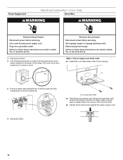
... 40 amp power supply cord. Failure to the terminal block. ■ Tighten strain relief screw against the power supply cord. 4. Electrically ground range. Style 1: Power supply cord strain relief ■ Assemble a UL listed strain relief in death, fire, or electrical shock. UL listed strain... block cover screw located on bottom of the terminal block. Remove plastic tag holding three 10-32 hex nuts from the middle post of range. Use Phillips screwdriver to remove cover. A 3. A. U.S.A. Use 8 gauge copper or 6 gauge aluminum wire. Power Supply Cord Electrical ...
... 40 amp power supply cord. Failure to the terminal block. ■ Tighten strain relief screw against the power supply cord. 4. Electrically ground range. Style 1: Power supply cord strain relief ■ Assemble a UL listed strain relief in death, fire, or electrical shock. UL listed strain... block cover screw located on bottom of the terminal block. Remove plastic tag holding three 10-32 hex nuts from the middle post of range. Use Phillips screwdriver to remove cover. A 3. A. U.S.A. Use 8 gauge copper or 6 gauge aluminum wire. Power Supply Cord Electrical ...

Installation Instruction
Page 15
... to remove screws and slide cord/conduit plate down and out. Replace back panel and screws on back of range. ■ Position cord/conduit plate as shown in the opening. ■ Use Phillips screwdriver to the terminal...not available) 15 NUCQPTUROAUSSERRIEMWTADEOLIÓTCAVLNHOSAENEPTTELEOAUTÉCWGEIQCTR!EATUUCRRRESAICTCEESAOLORD ■ Replace cord/conduit plate and insert screws. ■ Lift range back panel up and off. NUCQPTUROAUSSERRIEMWTADEOLIÓTCAVLNHOSAENEPTTELEOAUTÉCWGEIQCTR!EATUUCRRRESAICTCEESAOLORD ■ Assemble a UL listed conduit connector in the ...
... to remove screws and slide cord/conduit plate down and out. Replace back panel and screws on back of range. ■ Position cord/conduit plate as shown in the opening. ■ Use Phillips screwdriver to the terminal...not available) 15 NUCQPTUROAUSSERRIEMWTADEOLIÓTCAVLNHOSAENEPTTELEOAUTÉCWGEIQCTR!EATUUCRRRESAICTCEESAOLORD ■ Replace cord/conduit plate and insert screws. ■ Lift range back panel up and off. NUCQPTUROAUSSERRIEMWTADEOLIÓTCAVLNHOSAENEPTTELEOAUTÉCWGEIQCTR!EATUUCRRRESAICTCEESAOLORD ■ Assemble a UL listed conduit connector in the ...

Installation Instruction
Page 16
... Allow enough slack to easily attach the wiring to : 4-wire receptacle (NEMA type 14-50R) A UL listed, 250-volt minimum, 40-amp, range power supply cord 4-wire connection: Power supply cord 4-wire direct 5" (12.7 cm) 3-wire receptacle (NEMA type 10-50R) A fused disconnect or ...circuit breaker box A UL listed, 250-volt minimum, 40-amp, range power supply cord 4-wire connection: Direct wire 3-wire connection: Power supply cord 3-wire direct 1" (2.5 cm) 3" (7.6 cm) A fused disconnect or circuit breaker...
... Allow enough slack to easily attach the wiring to : 4-wire receptacle (NEMA type 14-50R) A UL listed, 250-volt minimum, 40-amp, range power supply cord 4-wire connection: Power supply cord 4-wire direct 5" (12.7 cm) 3-wire receptacle (NEMA type 10-50R) A fused disconnect or ...circuit breaker box A UL listed, 250-volt minimum, 40-amp, range power supply cord 4-wire connection: Direct wire 3-wire connection: Power supply cord 3-wire direct 1" (2.5 cm) 3" (7.6 cm) A fused disconnect or circuit breaker...

Installation Instruction
Page 17
... covering back 3" (7.6 cm) to easily attach the wiring terminal block. 3. Ground-link screw C. Ground-link screw D. Depending on bottom of the range. Strip the insulation back 1" (2.5 cm) from the back of range. A B A E C D B C A. 10-32 hex nut B. Securely tighten hex nuts. Save the ground-link screw and the end of the 10-32... New branch-circuit installations (1996 NEC) ■ Mobile homes ■ Recreational vehicles ■ In an area where local codes prohibit grounding through the opening , with ranges. 5. Feed the power supply cord through the neutral 1.
... covering back 3" (7.6 cm) to easily attach the wiring terminal block. 3. Ground-link screw C. Ground-link screw D. Depending on bottom of the range. Strip the insulation back 1" (2.5 cm) from the back of range. A B A E C D B C A. 10-32 hex nut B. Securely tighten hex nuts. Save the ground-link screw and the end of the 10-32... New branch-circuit installations (1996 NEC) ■ Mobile homes ■ Recreational vehicles ■ In an area where local codes prohibit grounding through the opening , with ranges. 5. Feed the power supply cord through the neutral 1.

Installation Instruction
Page 18
...Neutral (white) wire F. Loosen (do not remove) the setscrew on the front of the terminal lug and insert exposed wire end through bottom of range. Line 1 (black) C. Ground-link screw E. Terminal lug B. Line 2 (red) wire Bare Wire Torque Specifications Attaching terminal lugs to the ...hex nuts. 8. Neutral (white) wire E. Use Phillips screwdriver to connect the bare (green) ground wire to the center terminal block post with one of range. C F A. Ground-link screw C. Attach terminal lugs to torque as shown in . (4.0 N-m) 5. Bare (green) ground wire D. Terminal lug ...
...Neutral (white) wire F. Loosen (do not remove) the setscrew on the front of the terminal lug and insert exposed wire end through bottom of range. Line 1 (black) C. Ground-link screw E. Terminal lug B. Line 2 (red) wire Bare Wire Torque Specifications Attaching terminal lugs to the ...hex nuts. 8. Neutral (white) wire E. Use Phillips screwdriver to connect the bare (green) ground wire to the center terminal block post with one of range. C F A. Ground-link screw C. Attach terminal lugs to torque as shown in . (4.0 N-m) 5. Bare (green) ground wire D. Terminal lug ...

Installation Instruction
Page 20
... sides, pulling upward, and lifting out. 4. then front to side; f.) Check that electrical cords are not kinked. Vent clamp 2. Plug range into the downdraft blower motor. 8. A B A. Inlet flexible vent B. Check that the anti-tip bracket is installed and that rear leveling ... (on rack and check levelness of the range. ■ Look for satisfactory baking performance. 20 Range electrical connector to blower motor c.) If range is not level, pull range forward until range is level. Move range close to clear countertop. NOTE: Range must be level for the anti-tip bracket...
... sides, pulling upward, and lifting out. 4. then front to side; f.) Check that electrical cords are not kinked. Vent clamp 2. Plug range into the downdraft blower motor. 8. A B A. Inlet flexible vent B. Check that the anti-tip bracket is installed and that rear leveling ... (on rack and check levelness of the range. ■ Look for satisfactory baking performance. 20 Range electrical connector to blower motor c.) If range is not level, pull range forward until range is level. Move range close to clear countertop. NOTE: Range must be level for the anti-tip bracket...

Installation Instruction
Page 21
... Engaged 1. Wall Venting Top View B Side Venting (left side venting shown) Connect flexible vent duct to range and connect vent system to look underneath the bottom of the range. ■ Visually check that the rear foot is inserted into the slot of the anti-tip bracket.... 2. Range B. Range B D. Replace access panel. Vent system E. el. Verify the anti-tip bracket is installed and engaged. ■ Use a flashlight to blower motor outlet. Range B. Depending on your installation, connect the flexible vent from the blower...
... Engaged 1. Wall Venting Top View B Side Venting (left side venting shown) Connect flexible vent duct to range and connect vent system to look underneath the bottom of the range. ■ Visually check that the rear foot is inserted into the slot of the anti-tip bracket.... 2. Range B. Range B D. Replace access panel. Vent system E. el. Verify the anti-tip bracket is installed and engaged. ■ Use a flashlight to blower motor outlet. Range B. Depending on your installation, connect the flexible vent from the blower...


