Instruction Manual
Page 2
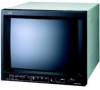
ENGLISH INSTRUCTIONS COLOR VIDEO MONITOR TM-H150CG Thank you for purchasing this JVC color video monitor. Before using it, read and follow all instructions carefully to take full advantage of the monitor's capabilities.
ENGLISH INSTRUCTIONS COLOR VIDEO MONITOR TM-H150CG Thank you for purchasing this JVC color video monitor. Before using it, read and follow all instructions carefully to take full advantage of the monitor's capabilities.
Instruction Manual
Page 3
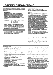
... no longer be determined by turning the equipment off and on the cord. Notice (U.S.A. near appliances generating strong magnetic fields, - Always refer servicing to qualified service personnel. ● When replacement parts are unable to insert the plug into the unit, - Improper operations, in operation as opening or removing covers may be sure to disconnect the power plug from the AC outlet. ●...
... no longer be determined by turning the equipment off and on the cord. Notice (U.S.A. near appliances generating strong magnetic fields, - Always refer servicing to qualified service personnel. ● When replacement parts are unable to insert the plug into the unit, - Improper operations, in operation as opening or removing covers may be sure to disconnect the power plug from the AC outlet. ●...
Instruction Manual
Page 4
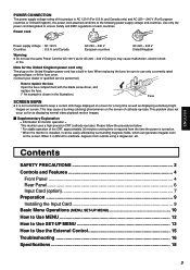
... the screen. Contents SAFETY PRECAUTIONS 2 Controls and Features 4 Front Panel ...4 Rear Panel ...6 Input Card (option 7 Preparation ...9 Installing the Input Card 9 Basic Menu Operations (MENU, SET-UP MENU 10 How to Use MENU 12 How to Use SET-UP MENU 13 How to eradicate, degauss from the time the power is shown in fuse. This problem does not occur as far as for monitor operation = This monitor uses a high precision CRT (cathode ray tube). When replacing...
... the screen. Contents SAFETY PRECAUTIONS 2 Controls and Features 4 Front Panel ...4 Rear Panel ...6 Input Card (option 7 Preparation ...9 Installing the Input Card 9 Basic Menu Operations (MENU, SET-UP MENU 10 How to Use MENU 12 How to Use SET-UP MENU 13 How to eradicate, degauss from the time the power is shown in fuse. This problem does not occur as far as for monitor operation = This monitor uses a high precision CRT (cathode ray tube). When replacing...

Instruction Manual
Page 5
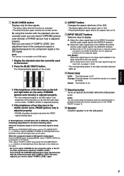
... to display a black and white image. Each time you press the button, the adjustment modes change . Pressing + or - NOTE: To display SET-UP MENU, press the fi button while holding down the MENU button. 5 UNDER SCAN button Reduces the screen size to display the entire image. • The button lights while this function is activated. • Pressing the button again restores the screen to normal size. 6 COLOR OFF button Cuts color signals to the RGB signal. 4 Controls and Features Front Panel 1 2 3 4 5678...
... to display a black and white image. Each time you press the button, the adjustment modes change . Pressing + or - NOTE: To display SET-UP MENU, press the fi button while holding down the MENU button. 5 UNDER SCAN button Reduces the screen size to display the entire image. • The button lights while this function is activated. • Pressing the button again restores the screen to normal size. 6 COLOR OFF button Cuts color signals to the RGB signal. 4 Controls and Features Front Panel 1 2 3 4 5678...
Instruction Manual
Page 6
... input to the input card installed in the middle are the same, "COMPO. by pressing the %/fi buttons. LEVEL." q Stand-by button is off the monitor when the main power is not available to the RGB signal. 1 Display the standard color-bar currently used , you need to the AUDIO A terminal. NOTE: This function is on. C/D (SLOT): Select the signal input to display. Green: The monitor is on. 3 If the brightness of the blue...
... input to the input card installed in the middle are the same, "COMPO. by pressing the %/fi buttons. LEVEL." q Stand-by button is off the monitor when the main power is not available to the RGB signal. 1 Display the standard color-bar currently used , you need to the AUDIO A terminal. NOTE: This function is on. C/D (SLOT): Select the signal input to display. Green: The monitor is on. 3 If the brightness of the blue...
Instruction Manual
Page 7
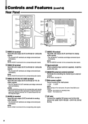
... corresponding audio signals. • When both an Y/C (S-video) signal and a composite signal are bridge-connected (auto termination). NOTES: • Use the AUDIO B terminals for composite signals. • The IN and OUT terminals are bridge-connected (auto termination). NOTE: Use the AUDIO B terminals for controlling the monitor by mode. • Green: The monitor is in stand-by an external control. \ For details, see page 15. ; o REMOTE (external control) terminal Terminals for the corresponding audio signals. Main power switch Turns...
... corresponding audio signals. • When both an Y/C (S-video) signal and a composite signal are bridge-connected (auto termination). NOTES: • Use the AUDIO B terminals for composite signals. • The IN and OUT terminals are bridge-connected (auto termination). NOTE: Use the AUDIO B terminals for controlling the monitor by mode. • Green: The monitor is in stand-by an external control. \ For details, see page 15. ; o REMOTE (external control) terminal Terminals for the corresponding audio signals. Main power switch Turns...

Instruction Manual
Page 8
... main power is turned off. • Even when the input signal is switched from this monitor: 525/60i, 625/50i 3 Connection terminal Attach to the connection terminal of the EMBEDDED AUDIO signal cannot be decoded (only the video signal can be used with the RGB input. To select RGB signal: Press the INPUT SELECT D button. • The IN and OUT terminals are bridge-connected. 7 The audio signal of the input card slot on SYNC cannot...
... main power is turned off. • Even when the input signal is switched from this monitor: 525/60i, 625/50i 3 Connection terminal Attach to the connection terminal of the EMBEDDED AUDIO signal cannot be decoded (only the video signal can be used with the RGB input. To select RGB signal: Press the INPUT SELECT D button. • The IN and OUT terminals are bridge-connected. 7 The audio signal of the input card slot on SYNC cannot...
Instruction Manual
Page 9
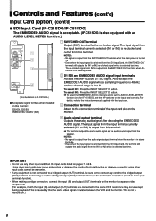
... power is turned off. • Even when the input signal is switched from the speaker. Such malfunction or damage caused by mode. Controls and Features (cont'd) Input Card (option) (cont'd) 7 SDI Input Card (IF-C21SDG/IF-C51SDG) The EMBEDDED AUDIO signal is acceptable. (IF-C51SDG is also equipped with the input card. 3 Connection terminal Attach to the connection terminal of the input card slot on the monitor. 4 Audio signal output terminal Outputs the analog audio signal...
... power is turned off. • Even when the input signal is switched from the speaker. Such malfunction or damage caused by mode. Controls and Features (cont'd) Input Card (option) (cont'd) 7 SDI Input Card (IF-C21SDG/IF-C51SDG) The EMBEDDED AUDIO signal is acceptable. (IF-C51SDG is also equipped with the input card. 3 Connection terminal Attach to the connection terminal of the input card slot on the monitor. 4 Audio signal output terminal Outputs the analog audio signal...
Instruction Manual
Page 10
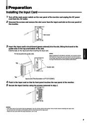
... the screws and remove the slot cover from the input card slot on the rear panel of the monitor. Refer to the instruction manual supplied with the input card and set the DIP switches on the input card correctly to set the DIP switches beforehand. ENGLISH Preparation Installing the Input Card 1 Turn off the main power of the monitor before installing the input card. • Do not touch the terminals or the patterns on the circuit board of the input card. •...
... the screws and remove the slot cover from the input card slot on the rear panel of the monitor. Refer to the instruction manual supplied with the input card and set the DIP switches on the input card correctly to set the DIP switches beforehand. ENGLISH Preparation Installing the Input Card 1 Turn off the main power of the monitor before installing the input card. • Do not touch the terminals or the patterns on the circuit board of the input card. •...
Instruction Manual
Page 11
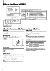
... signal input is selected (when INPUT C or INPUT D is selected and other signals than RGB is set at the factory. POSITION WHITE BALANCE CONTROL LOCK STATUS DISPLAY REMOTE SYSTEM INPUT REMOTE3) Functions The standard value ("00") of the blue signal. BRIGHT: Adjusts brightness. Adjusts the horizontal position of the red signal. G. The menu operations are also prohibited. LEVEL1) RUSH DELAY Functions Adjusts the picture aperture level. H. CONTRAST: Adjusts contrast. CUTOFF: Adjusts the cut -off point of the picture adjustment is initially set to display the color...
... signal input is selected (when INPUT C or INPUT D is selected and other signals than RGB is set at the factory. POSITION WHITE BALANCE CONTROL LOCK STATUS DISPLAY REMOTE SYSTEM INPUT REMOTE3) Functions The standard value ("00") of the blue signal. BRIGHT: Adjusts brightness. Adjusts the horizontal position of the red signal. G. The menu operations are also prohibited. LEVEL1) RUSH DELAY Functions Adjusts the picture aperture level. H. CONTRAST: Adjusts contrast. CUTOFF: Adjusts the cut -off point of the picture adjustment is initially set to display the color...
Instruction Manual
Page 12
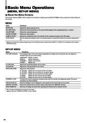
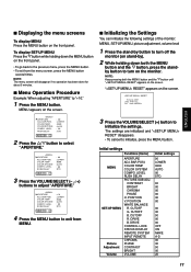
... : AUTO : 00 : STD. The settings are initialized and " RESET" disappears. • To cancel to "+10." 1 Press the MENU button. Initial settings Functions (Items) MENU SET-UP MENU Picture Adjustment Volume APERTURE ADJ. NOTE: The menu screen will disappear if no operation has been done for about 5 minutes. 7 Menu Operation Procedure Example: When adjusting "APERTURE" to initialize, press the MENU button. BAR POSI. POSITION V. DRIVE CONTROL LOCK STATUS DISPLAY REMOTE SYSTEM INPUT REMOTE CHROMA PHASE CONTRAST BRIGHT VOLUME Initial settings...
... : AUTO : 00 : STD. The settings are initialized and " RESET" disappears. • To cancel to "+10." 1 Press the MENU button. Initial settings Functions (Items) MENU SET-UP MENU Picture Adjustment Volume APERTURE ADJ. NOTE: The menu screen will disappear if no operation has been done for about 5 minutes. 7 Menu Operation Procedure Example: When adjusting "APERTURE" to initialize, press the MENU button. BAR POSI. POSITION V. DRIVE CONTROL LOCK STATUS DISPLAY REMOTE SYSTEM INPUT REMOTE CHROMA PHASE CONTRAST BRIGHT VOLUME Initial settings...
Instruction Manual
Page 13
... : AUTO : 00 : STD. MENU EXIT Exits from MENU. 7 Function, Contents, and the Adjustment Range of the entire system. LEVEL Adjusts the picture aperture level. • 00 " +40 ADJ. Selects the level bar position on the input signal. • NTSC: Keeps the NTSC color system. • PAL: Keeps the PAL color system. RUSH DELAY VOLUME : 20 COLOR TEMP. You can control the rush current of Each Item APERTURE COMPO. If the input signal is adjusted...
... : AUTO : 00 : STD. MENU EXIT Exits from MENU. 7 Function, Contents, and the Adjustment Range of the entire system. LEVEL Adjusts the picture aperture level. • 00 " +40 ADJ. Selects the level bar position on the input signal. • NTSC: Keeps the NTSC color system. • PAL: Keeps the PAL color system. RUSH DELAY VOLUME : 20 COLOR TEMP. You can control the rush current of Each Item APERTURE COMPO. If the input signal is adjusted...

Instruction Manual
Page 14
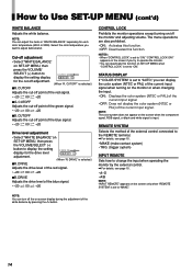
... picture adjustment is input. SELECT(-) - ENGLISH How to or exits from SET-UP MENU. POSITION : 00 V. Decreases the value (up to the minimum). When the signal with PAL color system is input, "PHASE" does not appear. POSITION Adjusts the vertical position of the screen. VOLUME/ - V. Select the video input you want to display the setting menu illustrated on screen display. Adjusts the horizontal position of the screen. H. VOLUME/ DRV Adjusts the drive level. on SET-UP MENU, then press the VOLUME/SELECT (+) button to adjust...
... picture adjustment is input. SELECT(-) - ENGLISH How to or exits from SET-UP MENU. POSITION : 00 V. Decreases the value (up to the minimum). When the signal with PAL color system is input, "PHASE" does not appear. POSITION Adjusts the vertical position of the screen. VOLUME/ - V. Select the video input you want to display the setting menu illustrated on screen display. Adjusts the horizontal position of the screen. H. VOLUME/ DRV Adjusts the drive level. on SET-UP MENU, then press the VOLUME/SELECT (+) button to adjust...
Instruction Manual
Page 15
... adjustment. (When "R. CUTOFF Adjusts the cut -off point of the blue signal. • -20 " 00 " +20 CONTROL LOCK Prohibits the monitor operations except turning on the screen when the component signal, RGB signal, or black-and-white signal is input. The menu operations are also prohibited. • ON: Activates this function. • OFF: Deactivates this function on the screen only when "REMOTE SYSTEM" is set to "ON." Select the color temperature...
... adjustment. (When "R. CUTOFF Adjusts the cut -off point of the blue signal. • -20 " 00 " +20 CONTROL LOCK Prohibits the monitor operations except turning on the screen when the component signal, RGB signal, or black-and-white signal is input. The menu operations are also prohibited. • ON: Activates this function. • OFF: Deactivates this function on the screen only when "REMOTE SYSTEM" is set to "ON." Select the color temperature...
Instruction Manual
Page 16
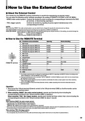
... INPUT B 4 Changes the input to INPUT C 5 Changes the input to INPUT D. A/B (1-pin control): Selects INPUT A or INPUT B by the external control. How to the 15th pin terminal (GND) for the operation by inputting the pulse signal instantaneously to "A/B." You can operate only one signal line of "REMOTE SYSTEM" in use 13 Not in SET-UP MENU: • MAKE (make contact system), you cannot change the input to INPUT C or INPUT D by the external control. • Opening: Changes...
... INPUT B 4 Changes the input to INPUT C 5 Changes the input to INPUT D. A/B (1-pin control): Selects INPUT A or INPUT B by the external control. How to the 15th pin terminal (GND) for the operation by inputting the pulse signal instantaneously to "A/B." You can operate only one signal line of "REMOTE SYSTEM" in use 13 Not in SET-UP MENU: • MAKE (make contact system), you cannot change the input to INPUT C or INPUT D by the external control. • Opening: Changes...
Instruction Manual
Page 17
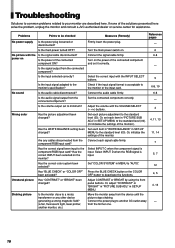
... connected component? Check if the input signal format is component/RGB input card? Has the correct INPUT been selected on . 6 No picture with the Is the signal cable disconnected? Measures (Remedy) Firmly insert the power plug. Turn the main power switch on the input. Connect the audio cable firmly. 6-8 Is the audio signal output from the connected component? Set each item in SET-UP MENU. 4, 13 Shaking picture Is the monitor close to another monitor, etc.) 16 Or, adjust "CONTRAST" or "BRIGHT" in SET...
... connected component? Check if the input signal format is component/RGB input card? Has the correct INPUT been selected on . 6 No picture with the Is the signal cable disconnected? Measures (Remedy) Firmly insert the power plug. Turn the main power switch on the input. Connect the audio cable firmly. 6-8 Is the audio signal output from the connected component? Set each item in SET-UP MENU. 4, 13 Shaking picture Is the monitor close to another monitor, etc.) 16 Or, adjust "CONTRAST" or "BRIGHT" in SET...
Instruction Manual
Page 18
... least 30 minutes, then turn the power off the monitor. Wrong picture position Has the picture position been changed with the power on the screen as a white cloth) is displayed for a long period, it is displayed. • You may shake or be operated by the external control the monitor can be distorted. front panel. Adjust "H. The following are not malfunctions: • When a bright still image (such as well. •...
... least 30 minutes, then turn the power off the monitor. Wrong picture position Has the picture position been changed with the power on the screen as a white cloth) is displayed for a long period, it is displayed. • You may shake or be operated by the external control the monitor can be distorted. front panel. Adjust "H. The following are not malfunctions: • When a bright still image (such as well. •...
Instruction Manual
Page 19
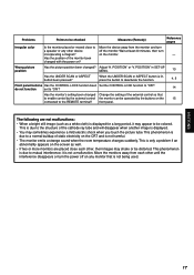
Specifications MODEL Type Color system Picture tube Effective screen size Scanning frequency Horizontal resolution Input terminals VIDEO A VIDEO B AUDIO A AUDIO B REMOTE Audio power output Built-in speaker Environmental conditions Power requirements Power consumption Dimensions Weight Accessory TM-H150CG Color video monitor PAL, NTSC (3.58) 39 cm (15") measured diagonally, 90° deflection, in this manual are approximate. • E. & O. The appearance of 8 Ω Operation temperature: 5°C - 40°C (41°F - 104°F) Operation humidity: 20 % - 80 % (non-...
Specifications MODEL Type Color system Picture tube Effective screen size Scanning frequency Horizontal resolution Input terminals VIDEO A VIDEO B AUDIO A AUDIO B REMOTE Audio power output Built-in speaker Environmental conditions Power requirements Power consumption Dimensions Weight Accessory TM-H150CG Color video monitor PAL, NTSC (3.58) 39 cm (15") measured diagonally, 90° deflection, in this manual are approximate. • E. & O. The appearance of 8 Ω Operation temperature: 5°C - 40°C (41°F - 104°F) Operation humidity: 20 % - 80 % (non-...

Instruction Manual
Page 20
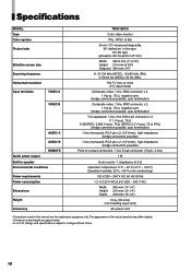
... (12 1/4) 3.5 (1/4) 3.5 (1/4) ENGLISH 238 (9 3/8) 20 ( 7/8) 60.2 (2 3/8) 308 (12 1/4) 7 Acceptable Signal Formats ‡: Acceptable -: Not acceptable Input Signals When an input card (not supplied) is installed IF-C01COMG IF-C01SDG IF-C21SDG IF-C51SDG NTSC (3.58 MHz) - - - - Black-and-White (50 Hz/60 Hz) - - - - 480/60i (525i) ‡ ‡ ‡ ‡ 576/50i (625i) ‡ ‡ ‡ ‡ EMBEDDED AUDIO - - ‡ ‡ Analog audio ‡ ‡...
... (12 1/4) 3.5 (1/4) 3.5 (1/4) ENGLISH 238 (9 3/8) 20 ( 7/8) 60.2 (2 3/8) 308 (12 1/4) 7 Acceptable Signal Formats ‡: Acceptable -: Not acceptable Input Signals When an input card (not supplied) is installed IF-C01COMG IF-C01SDG IF-C21SDG IF-C51SDG NTSC (3.58 MHz) - - - - Black-and-White (50 Hz/60 Hz) - - - - 480/60i (525i) ‡ ‡ ‡ ‡ 576/50i (625i) ‡ ‡ ‡ ‡ EMBEDDED AUDIO - - ‡ ‡ Analog audio ‡ ‡...

Instruction Manual
Page 21
VICTOR COMPANY OF JAPAN, LIMITED © 2004 VICTOR COMPANY OF JAPAN, LIMITED Printed in Thailand 0204MKH-MW-MT TM-H150CG COLOR VIDEO MONITOR
VICTOR COMPANY OF JAPAN, LIMITED © 2004 VICTOR COMPANY OF JAPAN, LIMITED Printed in Thailand 0204MKH-MW-MT TM-H150CG COLOR VIDEO MONITOR

