Instructions
Page 2
... plug to shut the power off and on a circuit different from that may cause harmful interference to correct the interference by one or more of the device. For U.S.A Declaration of Conformity: Trade Name: JVC Model Number: RX-D302B This device complies with the limits for help. This transmitter must accept any interference received, including interference that to which can radiate radio frequency...
... plug to shut the power off and on a circuit different from that may cause harmful interference to correct the interference by one or more of the device. For U.S.A Declaration of Conformity: Trade Name: JVC Model Number: RX-D302B This device complies with the limits for help. This transmitter must accept any interference received, including interference that to which can radiate radio frequency...
Instructions
Page 3
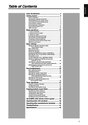
...remote control 4 Connecting the FM and AM antennas 5 Connecting the speakers 6 Connecting video components 7 Connecting the power cord 11 USB connection 12 Basic operations 14 1 Turn on the power 14 2 Select the source to play 14 3 Adjust the volume 15 Selecting the digital decode mode 15 Turning off the sounds temporarily 15 Changing the display brightness 16 Turning off the power with the Sleep Timer 16 Making sounds natural 16 Basic settings 17 Setting the speaker information easily -Quick Speaker Setup 17 Basic setting items 18 Operating procedure 19 Setting the speakers...
...remote control 4 Connecting the FM and AM antennas 5 Connecting the speakers 6 Connecting video components 7 Connecting the power cord 11 USB connection 12 Basic operations 14 1 Turn on the power 14 2 Select the source to play 14 3 Adjust the volume 15 Selecting the digital decode mode 15 Turning off the sounds temporarily 15 Changing the display brightness 16 Turning off the power with the Sleep Timer 16 Making sounds natural 16 Basic settings 17 Setting the speaker information easily -Quick Speaker Setup 17 Basic setting items 18 Operating procedure 19 Setting the speakers...

Instructions
Page 5
...) DIGITAL AUTO, LINEAR PCM, , ! R w Speakers terminals (6) SURROUND BACK SPEAKERS, SURROUND SPEAKERS, CENTER SPEAKER, FRONT SPEAKERS 3 L, SURR - Signal and speaker indicators (16) @ NEO:6 indicator (30) # VIRTUAL SB indicator (32) $ 3D-PHONIC indicator (30, 31) % DSP indicator (30, 31) ^ and indicator (29 - 31) & Main display * B (bass).BOOST indicator (25) ( MIDNIGHT indicator (21) ) Frequency unit indicators MHz (for FM stations), kHz (for details. Front panel 1 2345 AUDIO/VIDEO CONTROL RECEIVER STANDBY/ON CC CONVERTER SETTING ADJUST SURROUND PHONES USB 6 DVD...
...) DIGITAL AUTO, LINEAR PCM, , ! R w Speakers terminals (6) SURROUND BACK SPEAKERS, SURROUND SPEAKERS, CENTER SPEAKER, FRONT SPEAKERS 3 L, SURR - Signal and speaker indicators (16) @ NEO:6 indicator (30) # VIRTUAL SB indicator (32) $ 3D-PHONIC indicator (30, 31) % DSP indicator (30, 31) ^ and indicator (29 - 31) & Main display * B (bass).BOOST indicator (25) ( MIDNIGHT indicator (21) ) Frequency unit indicators MHz (for FM stations), kHz (for details. Front panel 1 2345 AUDIO/VIDEO CONTROL RECEIVER STANDBY/ON CC CONVERTER SETTING ADJUST SURROUND PHONES USB 6 DVD...

Instructions
Page 8
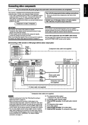
... end of each speaker cord. 2 Open the terminal (1), then insert the speaker cord (2). • For each speaker, connect the (+) and (-) terminals on the rear panel to the manual supplied with your subwoofer. Connect the input jack of you like since bass sound is non-directional. After connecting all components before making connections. connect the surround back speaker to the left surround back speaker terminal. (No sound comes from the speaker if you connect it in digital software. Speaker Layout Diagram SW L C R LS RS...
... end of each speaker cord. 2 Open the terminal (1), then insert the speaker cord (2). • For each speaker, connect the (+) and (-) terminals on the rear panel to the manual supplied with your subwoofer. Connect the input jack of you like since bass sound is non-directional. After connecting all components before making connections. connect the surround back speaker to the left surround back speaker terminal. (No sound comes from the speaker if you connect it in digital software. Speaker Layout Diagram SW L C R LS RS...
Instructions
Page 9
... the component video input jacks, select the component video input mode (DVD VIDEO IN) correctly. IMPORTANT: This receiver can get a better picture quality in VCR; When converting video signals, there are completed. DO NOT use the digital coaxial terminal (DIGITAL IN 1 (DVR/DVD)). English Connecting video components Do not connect the AC power plug to the wall outlet until all components before making connections. • When you cannot view the playback picture on the TV or the AV COMPU LINK remote control system cannot operate...
... the component video input jacks, select the component video input mode (DVD VIDEO IN) correctly. IMPORTANT: This receiver can get a better picture quality in VCR; When converting video signals, there are completed. DO NOT use the digital coaxial terminal (DIGITAL IN 1 (DVR/DVD)). English Connecting video components Do not connect the AC power plug to the wall outlet until all components before making connections. • When you cannot view the playback picture on the TV or the AV COMPU LINK remote control system cannot operate...

Instructions
Page 10
... composite video input About "DVD MULTI" When you select "DVD MULTI" as the source (see pages 29 to select analog discrete output mode on the TV or the AV COMPU LINK remote control system cannot operate properly. When a DVD Audio disc is played back, the original highquality sounds can enjoy analog discrete output sound (5.1-channel reproduction) from the connected component. • You may need to 33) are not available for enjoying DVD Audio sounds. NOTES • When using this connection. English 7 Connecting a DVD...
... composite video input About "DVD MULTI" When you select "DVD MULTI" as the source (see pages 29 to select analog discrete output mode on the TV or the AV COMPU LINK remote control system cannot operate properly. When a DVD Audio disc is played back, the original highquality sounds can enjoy analog discrete output sound (5.1-channel reproduction) from the connected component. • You may need to 33) are not available for enjoying DVD Audio sounds. NOTES • When using this connection. English 7 Connecting a DVD...

Instructions
Page 11
... not connect the AC power plug to the wall outlet until all connections are completed. 7 Connecting a VCR Turn off all components before making connections. • When you cannot view the playback picture on page 14. • When connecting a VCR to the component video input jacks, select the component video input mode (VCR VIDEO IN) correctly. When shipped from the factory, the audio input mode for details. • You can enjoy digital sound if using a digital coaxial or optical cable. For details of digital connection, see...
... not connect the AC power plug to the wall outlet until all connections are completed. 7 Connecting a VCR Turn off all components before making connections. • When you cannot view the playback picture on page 14. • When connecting a VCR to the component video input jacks, select the component video input mode (VCR VIDEO IN) correctly. When shipped from the factory, the audio input mode for details. • You can enjoy digital sound if using a digital coaxial or optical cable. For details of digital connection, see...
Instructions
Page 13
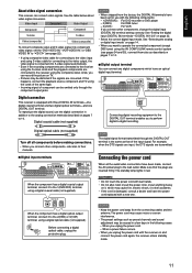
...) Turn off all the audio/video connections have an optical digital input terminal. NOTES • When shipped from the connecting cables and the antenna. Before connecting a digital optical cable, unplug the protective plug. When a power failure occurs. • When you want to operate the connected component (except DBS tuner) using the AV COMPU LINK remote control system (see page 22). • If using composite video cable for connecting to the video input and using S-video cable for use the digital connection in addition to 10. The standby lamp lights...
...) Turn off all the audio/video connections have an optical digital input terminal. NOTES • When shipped from the connecting cables and the antenna. Before connecting a digital optical cable, unplug the protective plug. When a power failure occurs. • When you want to operate the connected component (except DBS tuner) using the AV COMPU LINK remote control system (see page 22). • If using composite video cable for connecting to the video input and using S-video cable for use the digital connection in addition to 10. The standby lamp lights...

Instructions
Page 14
... no sound signal is difficult to connect the transmitter directly to the USB connector or the transmitter becomes obstacle to the USB connector of the receiver stops flashing and lights up . Turn on the transmitter light up . 7. Turn on the rear panel. • Tighten the screw with a USB cable (not supplied). (USB TERMINAL) When you connect your PC with the receiver. Connect the receiver to the USB WIRELESS ANTENNA terminal on the receiver, and select the source as "USB WIRELESS." Connect the antenna...
... no sound signal is difficult to connect the transmitter directly to the USB connector or the transmitter becomes obstacle to the USB connector of the receiver stops flashing and lights up . Turn on the transmitter light up . 7. Turn on the rear panel. • Tighten the screw with a USB cable (not supplied). (USB TERMINAL) When you connect your PC with the receiver. Connect the receiver to the USB WIRELESS ANTENNA terminal on the receiver, and select the source as "USB WIRELESS." Connect the antenna...
Instructions
Page 15
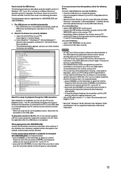
The USB drivers are installed automatically. • If the USB drivers are correctly installed. 1. To play back sounds on the PC, refer to the manuals supplied with the USB WIRELESS switch on the receiver "ON." - If no sound comes from CH 1 up to CH 13. - open the Control Panel on your PC, select [Sounds and Audio Devices] = [Audio] tab = [Sound playback] = [Default device], and check [Default device] is 1.5 m. * Microsoft®, Windows® 98 SE, Windows...
The USB drivers are installed automatically. • If the USB drivers are correctly installed. 1. To play back sounds on the PC, refer to the manuals supplied with the USB WIRELESS switch on the receiver "ON." - If no sound comes from CH 1 up to CH 13. - open the Control Panel on your PC, select [Sounds and Audio Devices] = [Audio] tab = [Sound playback] = [Default device], and check [Default device] is 1.5 m. * Microsoft®, Windows® 98 SE, Windows...

Instructions
Page 21
... can adjust the subwoofer output level (see below). Ex.: When setting DIGITAL IN 1 terminal. 1 Press SETTING. The current setting of all connections are completed. • If you have used Quick Speaker Setup on the display. • As you connect it to the left surround back speaker terminal (see page 6). Setting the speakers To obtain the best possible surround effect from step 1 again. SUBWFR SUBWFR Select when you have connected a subwoofer. Select when you have selected "SML...
... can adjust the subwoofer output level (see below). Ex.: When setting DIGITAL IN 1 terminal. 1 Press SETTING. The current setting of all connections are completed. • If you have used Quick Speaker Setup on the display. • As you connect it to the left surround back speaker terminal (see page 6). Setting the speakers To obtain the best possible surround effect from step 1 again. SUBWFR SUBWFR Select when you have connected a subwoofer. Select when you have selected "SML...

Instructions
Page 22
... Dolby Digital Surround EX and DTS-ES software, 6.1-channel reproduction is applied*. • For other multi-channel (more than 4 channel) encoded software, 5.1-channel reproduction is applied for digital multi-channel software vary-EX/ES/PLIIx (7.1-channel) reproduction or 5.1-channel reproduction. Initial setting: UNIT 7 Speaker distance- In this case, select "" to both 5.1-channel and 6.1channel encoded software. English Setting the speaker distance The distance from the Surround/DSP modes. UNIT Select to set to obtain the best possible sound effect...
... Dolby Digital Surround EX and DTS-ES software, 6.1-channel reproduction is applied*. • For other multi-channel (more than 4 channel) encoded software, 5.1-channel reproduction is applied for digital multi-channel software vary-EX/ES/PLIIx (7.1-channel) reproduction or 5.1-channel reproduction. Initial setting: UNIT 7 Speaker distance- In this case, select "" to both 5.1-channel and 6.1channel encoded software. English Setting the speaker distance The distance from the Surround/DSP modes. UNIT Select to set to obtain the best possible sound effect...

Instructions
Page 24
... source. Selecting the component video input mode-DVD VIDEO IN/VCR VIDEO IN/ DBS VIDEO IN When you cannot view the playback picture on the display.) ONETOUCH Select this case, "VCR" is selected. Select when connecting the VCR to the component video input jacks. ONETOUCH Select to store the volume level separately for each source. (The ONE TOUCH OPERATION indicator lights up on the TV or the AV COMPU LINK remote control system cannot operate properly (see page 34). English Setting the digital input (DIGITAL...
... source. Selecting the component video input mode-DVD VIDEO IN/VCR VIDEO IN/ DBS VIDEO IN When you cannot view the playback picture on the display.) ONETOUCH Select this case, "VCR" is selected. Select when connecting the VCR to the component video input jacks. ONETOUCH Select to store the volume level separately for each source. (The ONE TOUCH OPERATION indicator lights up on the TV or the AV COMPU LINK remote control system cannot operate properly (see page 34). English Setting the digital input (DIGITAL...

Instructions
Page 27
... modes-EFFECT This setting is available only when one of the DSP modes (except ALL CH STEREO) is activated for the Surround/DSP modes You can boost the bass level-Bass Boost. • Once you have made an adjustment, it is in use . ATT ATT Select to boost the bass level. The INPUT ATT indicator lights up on the display. Adjusting the sound parameters for the analog or digital 2-channel sound signal. PANORAMA Select...
... modes-EFFECT This setting is available only when one of the DSP modes (except ALL CH STEREO) is activated for the Surround/DSP modes You can boost the bass level-Bass Boost. • Once you have made an adjustment, it is in use . ATT ATT Select to boost the bass level. The INPUT ATT indicator lights up on the display. Adjusting the sound parameters for the analog or digital 2-channel sound signal. PANORAMA Select...

Instructions
Page 28
... cannot use the remote control for this setting. Normally, select "0.3." Normally, select "3." • When the center tone is activated for the analog or digital 2-channel sound signal. Normally, select "3." Normally, select "4." Adjustable range: 1 to "NO" (see page 33. • Once you change the setting. • You cannot use . To activate Surround/DSP mode, see page 33. • If "CENTER SPK" is set to 7 (in use the remote control for this setting. Adjusting the sound localization of the Surround/DSP modes...
... cannot use the remote control for this setting. Normally, select "0.3." Normally, select "3." • When the center tone is activated for the analog or digital 2-channel sound signal. Normally, select "3." Normally, select "4." Adjustable range: 1 to "NO" (see page 33. • Once you change the setting. • You cannot use . To activate Surround/DSP mode, see page 33. • If "CENTER SPK" is set to 7 (in use the remote control for this setting. Adjusting the sound localization of the Surround/DSP modes...

Instructions
Page 31
... front channel, right front channel, center channel, left surround channel, right surround channel, and LFE channel signals (total 6 channels, but the LFE channel is a digital surround encoding format that adds the third surround channels, called 5.1 channel). You can enjoy wide and deep sounds. English Creating realistic sound fields Reproducing theater ambience In a movie theater, many speakers, sound localization and sound movement can be expressed. Surround/DSP modes built in this receiver can feel in a real movie theater. Dolby Digital enables stereo surround sounds, and sets...
... front channel, right front channel, center channel, left surround channel, right surround channel, and LFE channel signals (total 6 channels, but the LFE channel is a digital surround encoding format that adds the third surround channels, called 5.1 channel). You can enjoy wide and deep sounds. English Creating realistic sound fields Reproducing theater ambience In a movie theater, many speakers, sound localization and sound movement can be expressed. Surround/DSP modes built in this receiver can feel in a real movie theater. Dolby Digital enables stereo surround sounds, and sets...

Instructions
Page 35
... setting. *2 Available Surround modes vary depending on the speaker settings and the incoming signals. On the front panel: 2 1,3 Before you select "AUTO SURROUND" You can adjust the following settings: CENTER WIDTH (see page 26) DIMENSION (see page 26) PANORAMA (see page 32. *3 If an incoming signal is a multi-channel (more than DVD MULTI. • Make sure you want . While playing an analog source, - Ex.: When "DOLBY DIGITAL" is selected for Dolby Digital multi-channel software: DIGITAL AUTO L C R S.WFR LFE DIGITAL LS RS AUTO SURROUND*1 Surround modes...
... setting. *2 Available Surround modes vary depending on the speaker settings and the incoming signals. On the front panel: 2 1,3 Before you select "AUTO SURROUND" You can adjust the following settings: CENTER WIDTH (see page 26) DIMENSION (see page 26) PANORAMA (see page 32. *3 If an incoming signal is a multi-channel (more than DVD MULTI. • Make sure you want . While playing an analog source, - Ex.: When "DOLBY DIGITAL" is selected for Dolby Digital multi-channel software: DIGITAL AUTO L C R S.WFR LFE DIGITAL LS RS AUTO SURROUND*1 Surround modes...
Instructions
Page 37
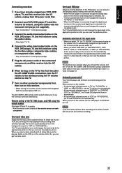
... this receiver using the S-video cables, composite video cables, or component video cables. • See "Connections 2" on the previous page. 5 Plug the AC power cords of the TV, DVD player, and VCR using the TV volume control on the TV. 7 Turn on other switches manually. • When the DVD player is connected through the analog input jacks on this receiver (and analog input is selected), the receiver automatically turns on and changes the source to "DVR/DVD" or "DVD MULTI." • When the DVD player is connected through the digital input...
... this receiver using the S-video cables, composite video cables, or component video cables. • See "Connections 2" on the previous page. 5 Plug the AC power cords of the TV, DVD player, and VCR using the TV volume control on the TV. 7 Turn on other switches manually. • When the DVD player is connected through the analog input jacks on this receiver (and analog input is selected), the receiver automatically turns on and changes the source to "DVR/DVD" or "DVD MULTI." • When the DVD player is connected through the digital input...
Instructions
Page 43
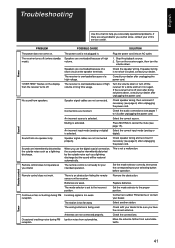
... the sound will be restored automatically. Remote control does not operate as you cannot solve, contact your dealer. Remote control does not work. Speakers are not connected properly. Stop the playback source. 2. Check the speaker wiring. If speaker wiring is overloaded because of high volume or long time usage. The receiver is not short-circuited, contact your JVC's service center. If the receiver turns off (enters standby mode). Speaker signal cables are weak. Check the audio connections (see...
... the sound will be restored automatically. Remote control does not operate as you cannot solve, contact your dealer. Remote control does not work. Speakers are not connected properly. Stop the playback source. 2. Check the speaker wiring. If speaker wiring is overloaded because of high volume or long time usage. The receiver is not short-circuited, contact your JVC's service center. If the receiver turns off (enters standby mode). Speaker signal cables are weak. Check the audio connections (see...

Instructions
Page 44
... 1 kHz with this receiver supports Direct Sequence Spreading Spectrum (DSSS) using 2.4 GHz frequency band. 42 Surround channels: 110 W per channel, min. Surround back channels: 110 W per channel, min. Audio Audio Input Sensitivity/Impedance: DVR/DVD (DVD MULTI), VCR, DBS, TV: 270 mV/47 kΩ Audio Input (DIGITAL IN)*: Coaxial: DIGITAL IN 1(DVR/DVD): 0.5 V(p-p)/75 Ω Optical: DIGITAL IN 2(DBS), 3(VCR): -21 dBm to -15 dBm (660 nm ±30 nm) USB: USB WIRELESS USB TERMINAL * Corresponding to 20...
... 1 kHz with this receiver supports Direct Sequence Spreading Spectrum (DSSS) using 2.4 GHz frequency band. 42 Surround channels: 110 W per channel, min. Surround back channels: 110 W per channel, min. Audio Audio Input Sensitivity/Impedance: DVR/DVD (DVD MULTI), VCR, DBS, TV: 270 mV/47 kΩ Audio Input (DIGITAL IN)*: Coaxial: DIGITAL IN 1(DVR/DVD): 0.5 V(p-p)/75 Ω Optical: DIGITAL IN 2(DBS), 3(VCR): -21 dBm to -15 dBm (660 nm ±30 nm) USB: USB WIRELESS USB TERMINAL * Corresponding to 20...


