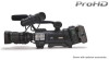
132 page operation manual for the GY-HM700 solid state camcorder
Page 1
... getting started: Thank you for purchasing this JVC product. which means the shipping destination. (U: for USA and Canada, E: for future reference. HD MEMORY CARD CAMERA RECORDER GY-HM700U INSTRUCTIONS GY-HM700CHU GY-HM700E GY-HM700CHE * The illustration shows the GY-HM700E with the supplied viewfinder, microphone and lens attached. * GY-HM700CHU/GY-HM700CHE does not come with a lens. In...
132 page operation manual for the GY-HM700 solid state camcorder
Page 6
... Basic System Diagram 15 Displays on the LCD Monitor and Viewfinder 16 Status Screen 16 Enlarged Status Display on LCD Monitor 17 Auto White Display (Camera Mode Only 18 Menu Setting Screen 18 Alarm Display 18 Zebra Pattern Display 18 Preparations Attaching Accessories 19 Attaching the Zoom Lens 19 Attaching the...
132 page operation manual for the GY-HM700 solid state camcorder
Page 7
...Status Screen in SD Card Mode 100 Status Screen in IEEE1394 Input Mode 102 Enlarged Status Display on LCD Monitor 103 Camera Features Marker and Safety Zone Displays (Camera Mode Only 104 Smoothening the Skin Color (Skin Detail Function) . . . . .106 Color Bar Output 107...of this manual are trademarks or registered trademarks of their respective companies. Unauthorized duplication or reprinting of this manual ● All rights reserved by JVC. Memo : Describes reference information, such as ™, ா and have been omitted in this manual. ● Illustrated designs...
132 page operation manual for the GY-HM700 solid state camcorder
Page 8
...video editing software from the GY-HD100 series which puts less stress on the editing computer. Recording in QuickTime File Format Recording can be made in addition to NLE as well as reduction of Recording Formats This camera recorder supports various HD formats ... more intuitive operations. Compact Shoulder Style By inheriting the compact shoulder style from Apple Inc. High Resolution LCD Monitor Equipped with a 4.3 inch 800x480 large LCD monitor, both shooting precision and viewing performance are automatically detected and displayed together with [JVC ProHD Clip Manager] and ...
132 page operation manual for the GY-HM700 solid state camcorder
Page 9
... this device from Panasonic, TOSHIBA or SanDisk may cause the surface to melt or turn cloudy. Blocking of wireless microphone near the camera When a wireless microphone or wireless microphone tuner is used near a heater for a few seconds immediately after the power is turned ... : Dionic90 (Anton Bauer) GY-HM700CHE/GY-HM700E : Endura-7 (IDX) * Models with benzene or thinner. Regular Inspection (Maintenance) Under normal environment, dust will not employ the UL Listing mark. Ⅵ Make use , put on the camera recorder when it is a precision equipment. Ⅵ Optical performance...
132 page operation manual for the GY-HM700 solid state camcorder
Page 10
...the image. sandy or dusty places; Characteristic CCD Phenomena Ⅵ Smear and blooming Due to produce white dots in damage of this camera recorder. Smear Vertical pale streaking appearing at high luminous object High luminous object (such as light bulbs, sun) Monitor Screen Blooming Blurring... does not increase. Do not remove the SDHC card during access either using high-precision technology. They will be damaged if the camera recorder is being accessed. Introduction Precautions for Proper Use (continued) Handling of SDHC Cards Ⅵ The access lamp lights up any...
132 page operation manual for the GY-HM700 solid state camcorder
Page 11
...is selected) USB Mode (USB mass storage class) [CAM/MEDIA] Button Operation Mode Indicator Stop Button Playback Button Operation Mode Camera Mode Operation Mode Indicator Blue Description This is set to AVariable FrameB, the operation mode indicator lights up in purple during ...thumbnail display in SD Card mode, thumbnails of the connected equipment are displayed. Operation Mode This camera recorder has three operation modes - Camera Mode Camera Mode Media Mode [CAM/MEDIA] Selection Button [CAM/MEDIA] Selection Button IEEE1394 Mode [CAM/MEDIA] Selection ...
132 page operation manual for the GY-HM700 solid state camcorder
Page 12
... White Balance Button (A Page 40) E Lens Lock Lever (A Page 19) F [MONITOR SELECT] Audio Monitor Selection Switch (A Page 45) G [DISPLAY] Display Button (A Page 29) H [CAM/MEDIA] Camera/Media Mode Selection Button (A Page 7) I [FULL AUTO] Full Auto Shooting (FAS) Switch (A Page 75) J Monitor Speaker (Cheek Pad) (A Page 26) K Shoe For mounting separately sold...
132 page operation manual for the GY-HM700 solid state camcorder
Page 13
... Screw Hole (x2) X [FOCUS ASSIST] Focus Assist Button (A Page 35) Y Record Button Lock Switch Set the switch toward the lens to CH-1 regardless of the camera recorder is not locked. Memo: ● The [REC] trigger button (A Page 10) K at the side control panel on the right of the setting. Z [REC] REC... input to lock the [REC] trigger button Z. Memo: ● The [REC] trigger button (A Page 10) K at the side control panel on the right of the camera recorder is interlocked with this button.
132 page operation manual for the GY-HM700 solid state camcorder
Page 14
... (A Page 74) Use these buttons function as below according to the operation mode (A Page 7). [USER1] Button [USER2] Button [USER3] Button During Camera Mode ● Activates the function assigned to [USER1] in the menu. ● Loads the [TC Preset] screen when pressed together with this button....) Center Set button (R) : Confirms menu items and setting values Cross-shaped button (JK) : Selects menu items and setting values Ⅵ During Camera mode Shutter operation: Center Set button (R) : Shutter ON/OFF Cross-shaped button (JK) : Switches shutter speed when shutter is ON AE level ...
132 page operation manual for the GY-HM700 solid state camcorder
Page 15
...-shaped button (H I ), center Set button (R) O Operation Mode Indicator Lights up as below according to the operation mode. (A Page 7) Operation Mode Camera Mode Media Mode (SD Card Mode) Media Mode (IEEE1394 Mode) USB Mode Color Blue/Purple Green Orange Orange Memo: ● You can select whether to... Viewfinder Eyepiece Lock Ring For loosening the ring and adjusting the eyepiece position of the viewfinder to the front or back. Memo: ● When [Camera Function]B[Switch Set]B[AE LEVEL] is set the number of frames during Variable Frame REC. (A Page 56 [Variable Frame REC]) (A Page 75 [AE...
132 page operation manual for the GY-HM700 solid state camcorder
Page 16
... For adjusting the shoulder pad position. G [AUDIO OUTPUT] Audio Output Terminal (RCA) Output terminal for DC 12 V power supply. Memo: ● Alarm tone is output during Camera mode. ● Playback audio signals are not in use. Introduction Names of the camera recorder. (A Page...(A Page 115) For selecting a valid IEEE1394 interface terminal. [EXT] [INT] : Enables IEEE1394 signals from input audio signals is not output. K Shoulder Pad L [USB] USB Terminal (A Page 118) M [IEEE1394] IEEE1394 Terminal (4-pin) For connecting digital video equipment with an AC adapter. To ...
132 page operation manual for the GY-HM700 solid state camcorder
Page 17
...switching SDHC cards. B Accessory Connector (Connects to withstand the weight of this camera recorder. ● If the shoulder belt is the illustration for GY-HM700CHE/GYHM700E. 13 Note: ● Be sure to use a shoulder belt with the strength to an optional accessory) C Battery Mounting Folder (A ...Page 21) The shape is different for GY-HM700CHU/GY-HM700U and GY-HM700CHE/GY-HM700E. * The above is not properly attached, the camera recorder may fall and cause injuries. ●...
132 page operation manual for the GY-HM700 solid state camcorder
Page 18
...Video Button Press this button to play back and check the latest clip, according to the settings under [Clip Review] of [Switch Set] in the [Camera Function] menu. (A Page 74) (A Page 52 [Viewing Recorded Videos Immediately (Clip Review)]) Memo: ● When [LENS RET] of [Switch Set... focus. Note: ● As the back focus knob is pressed. ● Zooms into telephoto and decreases the angle of Parts (continued) Zoom Lens (Supplied with GY-HM700U/GY-HM700E only) CANON KT14 x 4.4KRSJ C B A IRIS A M T W RET REC DE F G HI J M K L MANU. To take close-up shots of small objects. H ...
132 page operation manual for the GY-HM700 solid state camcorder
Page 20
... (A Page 7 [Operation Mode]) Ⅵ Status Screen in the normal screen. To display the status screen, press the [STATUS] button in Camera Mode (A Page 94) Viewfinder display The display switches between the 5 screen types with every press of the [STATUS] button. (STATUS 0B1B2B3B4B0) ...100 min 282min STATUS 1 Enlarged Display Screen (LCD monitor only) 16 Introduction Displays on the LCD monitor and viewfinder screens during shooting. Besides camera and playback images, the following characters are displayed on the LCD monitor and viewfinder. Ⅵ Status screen (A Page 16) Ⅵ Auto...
132 page operation manual for the GY-HM700 solid state camcorder
Page 21
... 0 Screen STATUS 1 Screen Enlarged Status Display on LCD Monitor You can enlarge and display only the characters of the status screen on the LCD monitor. (Camera mode only) CH1 CH2 DF FREE A STBY 1280 x 720 min 24p HQ B 100 min 282min STATUS 2 Screen Ⅵ Status Screen in Media Mode (IEEE1394 Mode...
132 page operation manual for the GY-HM700 solid state camcorder
Page 22
... Menu Setting Screen For configuring various settings. If the alarm sounds during STATUS 2 or 3 Screen display in Camera mode, the display will be displayed on the LCD Monitor and Viewfinder (continued) Auto White Display (Camera Mode Only) Displays the operation and result when Auto White Balance is activated. (A Page 40 [Adjusting the... front to STATUS 0 Screen and alarm will return to turn ON/OFF the zebra pattern display. ● Set the display pattern and luminance level in Camera mode (STATUS 0, 1, 4) and Media mode. Introduction Displays on this...
132 page operation manual for the GY-HM700 solid state camcorder
Page 23
Preparations Attaching Accessories Attaching the Zoom Lens (Supplied with GY-HM700U/GY-HM700E only) Hole 13 Pin REC 2 Clamp 4 1 Loosen the mount ring. 2 Attach the zoom lens such that the pin matches the hole of the camera recorder to AOFFB. Knob Microphone Microphone Holder Clamp [INPUT1/INPUT2] Terminal 19 Memo: ● Tighten the mount...
132 page operation manual for the GY-HM700 solid state camcorder
Page 24
...]) (A Page 21 [Using AC Power (DC IN Power)]) Note: ● Set the [POWER] switch to AOFFB before changing the power supply that operates this camera recorder. 1 Viewfinder 3 Attach the viewfinder cable to the viewfinder terminal. 4 Pin the viewfinder cable to secure the position of the viewfinder. Slide Lock Ring 2... Power Supply To use this camera recorder, you can attach a battery pack or connect an AC adapter to it . 2 Turn the slide lock ring to the clamp. 4 3 Clamp 20...
132 page operation manual for the GY-HM700 solid state camcorder
Page 25
...Listing mark. The battery will be supplied to AONB after turning on fully-charged batteries. Note: ● Make use power supply of the camera recorder to the camera recorder. When the power is connected to AOFFB. Remove the battery if you set the date/time. (A Page 25 [Setting the Clock... (Initial Setting)]) Battery Operating Time The following are not using the camera recorder. 21 When this happens, set the [POWER] switch to AONB to display the [Initial Setting] screen, then set the [POWER] switch to...