Instruction Manual
Page 1
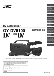
... FEATURES OF THE CAMERA SECTION OTHERS * The illustration shows the GY-DV5100 DV Camcorder with the optional lens, viewfinder and Microphone attached. Before operating this information for purchasing this JVC product. For Customer Use : Enter below the Serial No. which is located on the body. GY-DV5100 Serial No. LWT0230-001A-H Thank you for future reference. Model...
... FEATURES OF THE CAMERA SECTION OTHERS * The illustration shows the GY-DV5100 DV Camcorder with the optional lens, viewfinder and Microphone attached. Before operating this information for purchasing this JVC product. For Customer Use : Enter below the Serial No. which is located on the body. GY-DV5100 Serial No. LWT0230-001A-H Thank you for future reference. Model...
Instruction Manual
Page 2
... force, and uneven surfaces may fall, causing serious injury to a child or adult, and serious damage to overturn. 8. This appliance should use . 3. This will often require extensive work by the appliance manufacturer as the original part. Follow all of other similar surface. If liquid ...hazards. When the appliance exhibits a distinct change in a wet basement, or near or over a radiator or heat register. Do not use attachments not recommended by a qualified technician to restore the appliance to replace your electrician to normal operation. Do not locate this appliance ...
... force, and uneven surfaces may fall, causing serious injury to a child or adult, and serious damage to overturn. 8. This appliance should use . 3. This will often require extensive work by the appliance manufacturer as the original part. Follow all of other similar surface. If liquid ...hazards. When the appliance exhibits a distinct change in a wet basement, or near or over a radiator or heat register. Do not use attachments not recommended by a qualified technician to restore the appliance to replace your electrician to normal operation. Do not locate this appliance ...
Instruction Manual
Page 3
...NOT EXPOSE THIS APPLIANCE TO RAIN OR MOISTURE. Refer servicing to provide reasonable protection against harmful interference in accordance with the instructions, may be used with the limits for help. REMARQUE : La plaque d'identification (numéro de série) se trouve sur le panneau arriè... the equipment and receiver. ● Connect the equipment into an outlet on the top frame. CAUTION CHANGES OR MODIFICATIONS NOT APPROVED BY JVC COULD VOID USER'S AUTHORITY TO OPERATE THE EQUIPMENT. NOTE: The rating plate (serial number plate) is no guarantee that may cause harmfull...
...NOT EXPOSE THIS APPLIANCE TO RAIN OR MOISTURE. Refer servicing to provide reasonable protection against harmful interference in accordance with the instructions, may be used with the limits for help. REMARQUE : La plaque d'identification (numéro de série) se trouve sur le panneau arriè... the equipment and receiver. ● Connect the equipment into an outlet on the top frame. CAUTION CHANGES OR MODIFICATIONS NOT APPROVED BY JVC COULD VOID USER'S AUTHORITY TO OPERATE THE EQUIPMENT. NOTE: The rating plate (serial number plate) is no guarantee that may cause harmfull...
Instruction Manual
Page 4
...beginning of LOLUX mode ensures +36 dB gain. The following phenomena may occur when tapes recorded on other units (including another GY-DV5100) are recorded or played back on this unit may appear disturbed. ● Digital noise may appear during playback due to ...(4-pin) provided. Other use of copyright holders. ● JVC cannot assume liabilities that both standard-size DV videocassettes and mini-size DV videocassettes Recording/playback can be sure to 2084.6 Hz. ● DV (i. MAIN FEATURES ● Built-in compatible mechanism for GY-DV5100U. Recording or playback...
...beginning of LOLUX mode ensures +36 dB gain. The following phenomena may occur when tapes recorded on other units (including another GY-DV5100) are recorded or played back on this unit may appear disturbed. ● Digital noise may appear during playback due to ...(4-pin) provided. Other use of copyright holders. ● JVC cannot assume liabilities that both standard-size DV videocassettes and mini-size DV videocassettes Recording/playback can be sure to 2084.6 Hz. ● DV (i. MAIN FEATURES ● Built-in compatible mechanism for GY-DV5100U. Recording or playback...

Instruction Manual
Page 5
...1-4 Videocassette to be Used 8 1-5 Battery Pack to Use Skin Detail 94 OTHERS 13. BASIC SYSTEM CONNECTIONS AND ADJUSTMENTS 3-1 Basic System 31 3-2 Attaching the Zoom Lens 32 3-3 Attaching the Viewfinder 32 3-4 Attaching the Microphone (Provided 33 3-5 Attaching the Microphone (Optional 33 3-6... White Balance Adjustment 50 6-7 Audio Input Signal Selection 51 6-8 Recording Level Adjustment 52 6-9 Monitoring Audio during Recording 53 7. USING EXTERNAL COMPONENTS 9-1 Connecting a Video Component with DV Connector 65 10. POWER SUPPLY 4-1 AC Operation 35 4-2 Battery Pack Operation...
...1-4 Videocassette to be Used 8 1-5 Battery Pack to Use Skin Detail 94 OTHERS 13. BASIC SYSTEM CONNECTIONS AND ADJUSTMENTS 3-1 Basic System 31 3-2 Attaching the Zoom Lens 32 3-3 Attaching the Viewfinder 32 3-4 Attaching the Microphone (Provided 33 3-5 Attaching the Microphone (Optional 33 3-6... White Balance Adjustment 50 6-7 Audio Input Signal Selection 51 6-8 Recording Level Adjustment 52 6-9 Monitoring Audio during Recording 53 7. USING EXTERNAL COMPONENTS 9-1 Connecting a Video Component with DV Connector 65 10. POWER SUPPLY 4-1 AC Operation 35 4-2 Battery Pack Operation...
Instruction Manual
Page 6
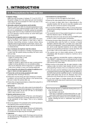
... or viewfinder may be damaged. ● The sensitivity level of the provided microphone is set the POWER switch to OFF in use, be damaged. ● Allowable ambient temperature and humidity Be sure to use the unit within the allowable temperature range of 0°C to 40°C ...and a relative humidity of wireless microphone near room heating equipment. ● Do not leave the unit where it is used for Proper Use ● Supply voltage Make sure that the unit returns to remove the detergent. INTRODUCTION 1-1 ...
... or viewfinder may be damaged. ● The sensitivity level of the provided microphone is set the POWER switch to OFF in use, be damaged. ● Allowable ambient temperature and humidity Be sure to use the unit within the allowable temperature range of 0°C to 40°C ...and a relative humidity of wireless microphone near room heating equipment. ● Do not leave the unit where it is used for Proper Use ● Supply voltage Make sure that the unit returns to remove the detergent. INTRODUCTION 1-1 ...
Instruction Manual
Page 7
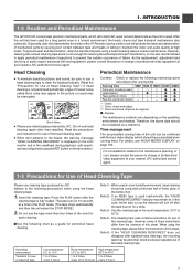
.... Insert the cleaning tape. indicator may remain on the operating environment and method. INTRODUCTION 1-2 Routine and Periodical Maintenance The GY-DV5100 incorporates precision mechanical parts, which shows the accumulated drum running time). However, cleaning with the hour meter display (which will...failing to clean the head periodically. (Read the "Precautions for use cleaning tape produced by JVC. Time management The accumulated running time. Note 3) Use the cleaning tape in charge of this sheet. When using the RET button on page 100. Note 5) If the ...
.... Insert the cleaning tape. indicator may remain on the operating environment and method. INTRODUCTION 1-2 Routine and Periodical Maintenance The GY-DV5100 incorporates precision mechanical parts, which shows the accumulated drum running time). However, cleaning with the hour meter display (which will...failing to clean the head periodically. (Read the "Precautions for use cleaning tape produced by JVC. Time management The accumulated running time. Note 3) Use the cleaning tape in charge of this sheet. When using the RET button on page 100. Note 5) If the ...

Instruction Manual
Page 8
...TYPE" on page 87. ☞See "BATTERY INFO" on page 82. * A flat shape type battery pack cannot be connected directly to be Used ● Use JVC's videocassette tapes marked with the " " or " " symbol. When housed in distortion of videotapes. INTRODUCTION 1-4 Videocassette to the camera. Standard DV...in a horizontal position, pressure from other tapes can cause distortions and deformations of the tape edges. 1-5 Battery Pack to be Used The GY-DV5100 can use any of the following instructions for the best recording and ● Do not leave the videotapes neglected for a long period ...
...TYPE" on page 87. ☞See "BATTERY INFO" on page 82. * A flat shape type battery pack cannot be connected directly to be Used ● Use JVC's videocassette tapes marked with the " " or " " symbol. When housed in distortion of videotapes. INTRODUCTION 1-4 Videocassette to the camera. Standard DV...in a horizontal position, pressure from other tapes can cause distortions and deformations of the tape edges. 1-5 Battery Pack to be Used The GY-DV5100 can use any of the following instructions for the best recording and ● Do not leave the videotapes neglected for a long period ...
Instruction Manual
Page 9
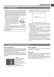
...air may be dissolved. ● To prevent condensation when moving the camera under conditions where the temperature of a CCD it to as possible, use until the internal parts have stabilized. ● "CONDENSATION ON DRUM" is referred to a new environment. As far as condensation (dewing). In...or when the unit is placed in the image. White dots High temperatures can cause CCD sensor pixels to condensation even before using it. 1-7 Characteristic CCD Phenomena Smear and Blooming Due to induce vertical streaking (called "blooming"). WARNING 0201 CONDENSATION ON DRUM Keep...
...air may be dissolved. ● To prevent condensation when moving the camera under conditions where the temperature of a CCD it to as possible, use until the internal parts have stabilized. ● "CONDENSATION ON DRUM" is referred to a new environment. As far as condensation (dewing). In...or when the unit is placed in the image. White dots High temperatures can cause CCD sensor pixels to condensation even before using it. 1-7 Characteristic CCD Phenomena Smear and Blooming Due to induce vertical streaking (called "blooming"). WARNING 0201 CONDENSATION ON DRUM Keep...
Instruction Manual
Page 10
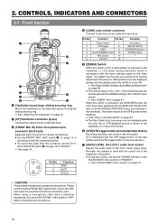
...Viewfinder" on page 89. ● The default value is set the FRONT MIC +48V switch to the "ON" side when the provided microphone should be used . Zebra patterns are also displayed during Manual Adjustment" on page 32. 2 [VF] Viewfinder connector (6-pin) Connect the cable from lens here... LEVEL CH-1 5 i u 1 Viewfinder mount base, sliding securing ring Mount the viewfinder on the base and secure it using a microphone other than a phantom microphone, first set to Use Skin Detail" on page 94. ● The Skin Detail color tone areas are indicated in accordance with the SKIN COLOR ...
...Viewfinder" on page 89. ● The default value is set the FRONT MIC +48V switch to the "ON" side when the provided microphone should be used . Zebra patterns are also displayed during Manual Adjustment" on page 32. 2 [VF] Viewfinder connector (6-pin) Connect the cable from lens here... LEVEL CH-1 5 i u 1 Viewfinder mount base, sliding securing ring Mount the viewfinder on the base and secure it using a microphone other than a phantom microphone, first set to Use Skin Detail" on page 94. ● The Skin Detail color tone areas are indicated in accordance with the SKIN COLOR ...

Instruction Manual
Page 11
... 14 is set to A or B, setting this switch is not activated in the LOLUX mode. 9 Lens mounting ring/Lens lock lever Hold the lens and use the lever to turn the ring clockwise until firm. ☞ See "Attaching the Zoom Lens" on page 32. 0 [FILTER] Color temperature conversion filter control knob...
... 14 is set to A or B, setting this switch is not activated in the LOLUX mode. 9 Lens mounting ring/Lens lock lever Hold the lens and use the lever to turn the ring clockwise until firm. ☞ See "Attaching the Zoom Lens" on page 32. 0 [FILTER] Color temperature conversion filter control knob...
Instruction Manual
Page 13
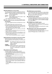
...] Camera mode indicator This indicator lights when the camera is in the VTR mode. B [VTR] Trigger button (Recording Start/Stop) This button is used to their optimum levels. "POFF" is displayed on the LCD monitor or in the viewfinder when the power is interlocked with the VTR trigger button... The gain will be shot. COMPRESS : When an entire image is relatively light and the contrast is low, the gain of the image is used to the maximum of the image. CONTROLS, INDICATORS AND CONNECTORS 5 [AUTO IRIS] Auto iris level switch This switch selects the automatic iris adjustment ...
...] Camera mode indicator This indicator lights when the camera is in the VTR mode. B [VTR] Trigger button (Recording Start/Stop) This button is used to their optimum levels. "POFF" is displayed on the LCD monitor or in the viewfinder when the power is interlocked with the VTR trigger button... The gain will be shot. COMPRESS : When an entire image is relatively light and the contrast is low, the gain of the image is used to the maximum of the image. CONTROLS, INDICATORS AND CONNECTORS 5 [AUTO IRIS] Auto iris level switch This switch selects the automatic iris adjustment ...
Instruction Manual
Page 14
... foreground subject, the background image will be memorized into B. In such a case, a clearer background is obtained when the auto knee function is used . A : If white balance is performed with the switch in this position, it will be blurred with a high-brightness background, if the ...original) H : 18 dB (boosted to OFF. Each time this switch. D [OUTPUT] Color bar/Camera/Auto knee switch This switch is used to input the DV signal from the shooting camera is selected, the auto knee function is insufficient illumination on the subject. It is effective especially...
... foreground subject, the background image will be memorized into B. In such a case, a clearer background is obtained when the auto knee function is used . A : If white balance is performed with the switch in this position, it will be blurred with a high-brightness background, if the ...original) H : 18 dB (boosted to OFF. Each time this switch. D [OUTPUT] Color bar/Camera/Auto knee switch This switch is used to input the DV signal from the shooting camera is selected, the auto knee function is insufficient illumination on the subject. It is effective especially...
Instruction Manual
Page 15
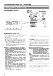
... monitor darker. ● Pushing the +/− buttons simultaneously returns the setting to the standard setting. 5 [DISPLAY] Display button This button is used to suppress the audio level. Only image displayed → Characters shown enlarged ↑ Image and characters displayed ← 6 [CH-1 AUDIO LEVEL...] CH-1 audio level control Adjust the audio level of the CH-1 audio channel with this control. ● To use this control, set to select the method for adjusting the audio level of the door. CONTROLS, INDICATORS AND CONNECTORS q we EDITSEARCH FILTER 1 ...
... monitor darker. ● Pushing the +/− buttons simultaneously returns the setting to the standard setting. 5 [DISPLAY] Display button This button is used to suppress the audio level. Only image displayed → Characters shown enlarged ↑ Image and characters displayed ← 6 [CH-1 AUDIO LEVEL...] CH-1 audio level control Adjust the audio level of the CH-1 audio channel with this control. ● To use this control, set to select the method for adjusting the audio level of the door. CONTROLS, INDICATORS AND CONNECTORS q we EDITSEARCH FILTER 1 ...
Instruction Manual
Page 16
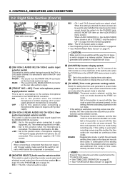
... , the time codes are output mixed. This switch is output. CH-1 : The CH-1 channel audio is used when recording scenes one after another requiring +48 V power supply (phantom microphone) is selected. ON : Set to select the monitor sound output and playback sound output from the FRONT MIC ..., and the time code run mode becomes the FREE run mode. * If this position when a microphone requiring +48 V power supply (phantom microphone, etc.) is set to +48V before the component is used to this setting is +4 dBs. Set to select the time code run mode during recording only. ...
... , the time codes are output mixed. This switch is output. CH-1 : The CH-1 channel audio is used when recording scenes one after another requiring +48 V power supply (phantom microphone) is selected. ON : Set to select the monitor sound output and playback sound output from the FRONT MIC ..., and the time code run mode becomes the FREE run mode. * If this position when a microphone requiring +48 V power supply (phantom microphone, etc.) is set to +48V before the component is used to this setting is +4 dBs. Set to select the time code run mode during recording only. ...
Instruction Manual
Page 17
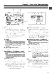
... Camera mode: The camera image is output. MEMO: ● Alarm sound is not output. 4 Microphone attachment holes For attaching the microphone holder KA-A50U (optional) when the optional microphone MV-P615U or MV-P618U is output in the VTR playback mode. When a DV signal (IEEE1394) ...is input, the EE image of the input video signal is output in the VTR mode. VTR mode: The playback image is used. ☞ See "Attaching the Microphone...
... Camera mode: The camera image is output. MEMO: ● Alarm sound is not output. 4 Microphone attachment holes For attaching the microphone holder KA-A50U (optional) when the optional microphone MV-P615U or MV-P618U is output in the VTR playback mode. When a DV signal (IEEE1394) ...is input, the EE image of the input video signal is output in the VTR mode. VTR mode: The playback image is used. ☞ See "Attaching the Microphone...

Instruction Manual
Page 19
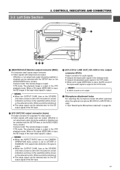
... circumstances. The audio output level is output. Set the MONITOR SELECT switch to the power supplied through this camera or a digital video component to a wireless microphone transmitter, etc. Set the AUDIO MONITOR item on page 16. Signal 1 GND 2 - 3 - 4 +12V 4 [DC OUT] DC output connector Connector for... Tally lamp This lamp lights up when the GY-DV5100 enters the record mode. Connect to the camera * Turn the camera off before using a stereotype jack and stereo sound should be connected here. The supply voltage is used to "REAR". This connector is identical to...
... circumstances. The audio output level is output. Set the MONITOR SELECT switch to the power supplied through this camera or a digital video component to a wireless microphone transmitter, etc. Set the AUDIO MONITOR item on page 16. Signal 1 GND 2 - 3 - 4 +12V 4 [DC OUT] DC output connector Connector for... Tally lamp This lamp lights up when the GY-DV5100 enters the record mode. Connect to the camera * Turn the camera off before using a stereotype jack and stereo sound should be connected here. The supply voltage is used to "REAR". This connector is identical to...

Instruction Manual
Page 20
2. CONTROLS, INDICATORS AND CONNECTORS 2-5 Rear Section (Cont'd) i o !0 8 Battery holder Mount Anton-Bauer battery pack here. 9 Battery release lever This release lever is used to put the camera in charge of professional video equipment at your nearest JVC-authorized service agent. 20 If no abnormalities and that there are no abnormalities are detected, press the...
2. CONTROLS, INDICATORS AND CONNECTORS 2-5 Rear Section (Cont'd) i o !0 8 Battery holder Mount Anton-Bauer battery pack here. 9 Battery release lever This release lever is used to put the camera in charge of professional video equipment at your nearest JVC-authorized service agent. 20 If no abnormalities and that there are no abnormalities are detected, press the...

Instruction Manual
Page 21
... normal screen. ● The DISPLAY button can be pressed to showing the EE image and the playback picture, the LCD monitor and viewfinder are also used for the VTR mode. ● Each time the STATUS button is displayed to ON, the character displays mentioned above are divided into those for the...
... normal screen. ● The DISPLAY button can be pressed to showing the EE image and the playback picture, the LCD monitor and viewfinder are also used for the VTR mode. ● Each time the STATUS button is displayed to ON, the character displays mentioned above are divided into those for the...

Instruction Manual
Page 23
... sampling.) Displays the CH-1, CH-2 audio level meters. Whether the time code or user's bits should be regarded only as a guide. * When the unit is used at the time the change is equivalent to display this screen displays the following items. No. Whether or not to less than 3 minutes. LEVEL" on...
... sampling.) Displays the CH-1, CH-2 audio level meters. Whether the time code or user's bits should be regarded only as a guide. * When the unit is used at the time the change is equivalent to display this screen displays the following items. No. Whether or not to less than 3 minutes. LEVEL" on...


