Instructions
Page 1
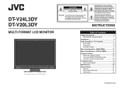
... DT-V20L3DY MULTI FORMAT LCD MONITOR The illustration of the monitor is intended to alert the user to constitute a risk of Contents Safety Precautions 2 IMPORTANT SAFEGUARDS 2 Installation 4 Daily Operations / Connections 6 Front panel 6 Rear panel 8 Available signals 9 Menu Configuration-MAIN MENU 10 Menu Configuration-SET-UP MENU 14 External Control 16 About the external control 16 Using the MAKE/TRIGGER system 17 Using the serial communication 18 Troubleshooting 19 Self-check program 20 Maintenance 20 Specifications...
... DT-V20L3DY MULTI FORMAT LCD MONITOR The illustration of the monitor is intended to alert the user to constitute a risk of Contents Safety Precautions 2 IMPORTANT SAFEGUARDS 2 Installation 4 Daily Operations / Connections 6 Front panel 6 Rear panel 8 Available signals 9 Menu Configuration-MAIN MENU 10 Menu Configuration-SET-UP MENU 14 External Control 16 About the external control 16 Using the MAKE/TRIGGER system 17 Using the serial communication 18 Troubleshooting 19 Self-check program 20 Maintenance 20 Specifications...

Instructions
Page 2
... plug/unplug the power cord, equip an easily accessible device to the wiring of the building for use of the product in the high temperature Do not use , and service. Caution for turning on the product may expose you cannot easily turn off the POWER switch, control the AC power supply by the manufacturer. • Do not use . • All the safety and operating instructions...
... plug/unplug the power cord, equip an easily accessible device to the wiring of the building for use of the product in the high temperature Do not use , and service. Caution for turning on the product may expose you cannot easily turn off the POWER switch, control the AC power supply by the manufacturer. • Do not use . • All the safety and operating instructions...
Instructions
Page 3
.... Servicing is used in accordance with the instruction manual, may be regulated in accordance with the manufacturer's instructions. 8) Do not install near water. 6) Clean only with dry cloth. 7) Do not block any heat sources such as sunshine, fire or the like. 17) When discarding batteries, environmental problems must.... The wide blade or the third prong are designed to provide reasonable protection against harmful interference when the equipment is operated in any way, such as power-supply cord or plug is likely to cause harmful interference in which case the user will be...
.... Servicing is used in accordance with the instruction manual, may be regulated in accordance with the manufacturer's instructions. 8) Do not install near water. 6) Clean only with dry cloth. 7) Do not block any heat sources such as sunshine, fire or the like. 17) When discarding batteries, environmental problems must.... The wide blade or the third prong are designed to provide reasonable protection against harmful interference when the equipment is operated in any way, such as power-supply cord or plug is likely to cause harmful interference in which case the user will be...
Instructions
Page 4
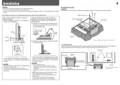
... lower position of lifting the stand up the stand... - When the stand plate is attached to the higher position of the stand body (☞ "To adjust the stand height" on the supplied stand. otherwise the monitor may cause damage to 0°, then reattach the removed screws. Then fix the stand firmly with the LCD panel facing down to prevent the LCD panel from being damaged. Screw holes for stand attachment Stand body Monitor The...
... lower position of lifting the stand up the stand... - When the stand plate is attached to the higher position of the stand body (☞ "To adjust the stand height" on the supplied stand. otherwise the monitor may cause damage to 0°, then reattach the removed screws. Then fix the stand firmly with the LCD panel facing down to prevent the LCD panel from being damaged. Screw holes for stand attachment Stand body Monitor The...

Instructions
Page 5
... fall Fix the monitor to a wall by choosing the screw holes to use the two holes on the rear panel of DT-V24L3DY. 5 Bind the hooks on the upper side) using M4 x 10 mm screws (not provided). To adjust the stand height To change the position of the stand plate according to the stand height you want by using durable string. Fixing the monitor Attach the hook (not provided) to the VESA mounting holes...
... fall Fix the monitor to a wall by choosing the screw holes to use the two holes on the rear panel of DT-V24L3DY. 5 Bind the hooks on the upper side) using M4 x 10 mm screws (not provided). To adjust the stand height To change the position of the stand plate according to the stand height you want by using durable string. Fixing the monitor Attach the hook (not provided) to the VESA mounting holes...
Instructions
Page 6
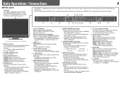
... lights. BRIGHT: Adjusts the picture brightness. RGB (Normal screen) Red screen Blue screen Green screen w ASPECT button/lamp Changes the aspect ratio of the time data (time code) contained in the 1:1 mode. r T.C. (time code) button/lamp Activates/deactivates the display of the picture from the AUDIO ASSIGN (MONITOR OUT) terminals. (☞ " 8 AUDIO ASSIGN (MONITOR OUT) terminals" on . y Power lamp Unlit: The monitor is completely off (the Power switch on the rear panel is on page 8) 2 VOLUME adjustment knob Adjusts the volume. 3 Picture adjustment knob PHASE: Adjusts the picture...
... lights. BRIGHT: Adjusts the picture brightness. RGB (Normal screen) Red screen Blue screen Green screen w ASPECT button/lamp Changes the aspect ratio of the time data (time code) contained in the 1:1 mode. r T.C. (time code) button/lamp Activates/deactivates the display of the picture from the AUDIO ASSIGN (MONITOR OUT) terminals. (☞ " 8 AUDIO ASSIGN (MONITOR OUT) terminals" on . y Power lamp Unlit: The monitor is completely off (the Power switch on the rear panel is on page 8) 2 VOLUME adjustment knob Adjusts the volume. 3 Picture adjustment knob PHASE: Adjusts the picture...
Instructions
Page 7
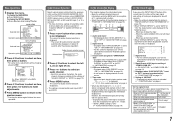
... 9. 2 Signal format of DVI input or setting of "COMPO./RGB SEL." ☞ "DVI INPUT SEL." When you press the button, the audio channel changes according to choose a group of input signals and their conditions. When you press the INPUT SELECT button of the current input, the status of the input signal and setting of muting are displayed for each information using the MENU with the exception of 5, controlled with a button. • Select the position...
... 9. 2 Signal format of DVI input or setting of "COMPO./RGB SEL." ☞ "DVI INPUT SEL." When you press the button, the audio channel changes according to choose a group of input signals and their conditions. When you press the INPUT SELECT button of the current input, the status of the input signal and setting of muting are displayed for each information using the MENU with the exception of 5, controlled with a button. • Select the position...
Instructions
Page 8
.... • When unplugging a cord, be firmly inserted; q DVI-D (HDCP) terminal Input terminal for the DVI-D signal compatible with a sampling frequency of the current EMBEDDED AUDIO signals in the audio level meter. (☞ "On the Information Display" on page 7) Make the setting for the level meter in "P.SAVE" (power save ) mode. (☞ "NO SYNC ACTION" on page 12). To detach the cover Using the audio level meter You can check the conditions of...
.... • When unplugging a cord, be firmly inserted; q DVI-D (HDCP) terminal Input terminal for the DVI-D signal compatible with a sampling frequency of the current EMBEDDED AUDIO signals in the audio level meter. (☞ "On the Information Display" on page 7) Make the setting for the level meter in "P.SAVE" (power save ) mode. (☞ "NO SYNC ACTION" on page 12). To detach the cover Using the audio level meter You can check the conditions of...
Instructions
Page 9
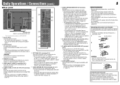
... Non-interlace Non-interlace *4 For DT-V20L3DY: When No. 9, 10, 12 or 14 signals come in, thin lines will become obscured because their signal resolution is higher than the screen resolution. • Non-preset signals may not be displayed normally even if their frequency is within the acceptable range (☞ "Horizontal/vertical frequency (computer signal)" on the status display. The separate sync signal (HS/VS) is shown on...
... Non-interlace Non-interlace *4 For DT-V20L3DY: When No. 9, 10, 12 or 14 signals come in, thin lines will become obscured because their signal resolution is higher than the screen resolution. • Non-preset signals may not be displayed normally even if their frequency is within the acceptable range (☞ "Horizontal/vertical frequency (computer signal)" on the status display. The separate sync signal (HS/VS) is shown on...
Instructions
Page 10
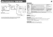
... LIGHT Setting value: -20 - +20 Adjusts the brightness of the luminance signal. Setting value: COMPO. (component), RGB Selects the signal type you want to use for each operation. • The menu automatically disappears in "PICTURE FUNCTION." *1 DT-V24L3DY only *2 Memorized for COMPO./RGB terminals. OFF, NORMAL, HARD LTI Adjust the clearness of the outlines of the display. OFF, NORMAL, HARD I/P MODE Selects a proper mode corresponding to the DVI...
... LIGHT Setting value: -20 - +20 Adjusts the brightness of the luminance signal. Setting value: COMPO. (component), RGB Selects the signal type you want to use for each operation. • The menu automatically disappears in "PICTURE FUNCTION." *1 DT-V24L3DY only *2 Memorized for COMPO./RGB terminals. OFF, NORMAL, HARD LTI Adjust the clearness of the outlines of the display. OFF, NORMAL, HARD I/P MODE Selects a proper mode corresponding to the DVI...

Instructions
Page 12
... the screen and 7 - 12 at the right.), DIVIDE (Displays the odd channels at the left speakers. Adjustment bar Displayed when selecting "BALANCE." • The menu automatically disappears in input levels), W.100 (white) REFERENCE LEVEL Select the standard input level indicated on the menu. Red Yellow Green • When "BAR TYPE" is assigned to "3COLORS" OVER LEVEL REFERENCE LEVEL 12 AUDIO SETTING Settings for the EMBEDDED AUDIO signals...
... the screen and 7 - 12 at the right.), DIVIDE (Displays the odd channels at the left speakers. Adjustment bar Displayed when selecting "BALANCE." • The menu automatically disappears in input levels), W.100 (white) REFERENCE LEVEL Select the standard input level indicated on the menu. Red Yellow Green • When "BAR TYPE" is assigned to "3COLORS" OVER LEVEL REFERENCE LEVEL 12 AUDIO SETTING Settings for the EMBEDDED AUDIO signals...

Instructions
Page 13
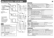
... color of the back light is saved by turning off automatically 15 minutes after signals stop coming in. DELAY TIME SYNC INPUT SEL.*2 LOW LATENCY Select the period until the screen status changes as follows: RGB input signals (analog/digital), DVI signals (digital/inputted from personal computer), 1080/60p (analog/digital), 1080/50p (analog/digital), 640 *480/60p (analog/digital). INT. (Internal sync), EXT. (External sync) ON, OFF • When setting "NO SYNC ACTION" to "GRAY B.," the screen color changes to "080" Red White...
... color of the back light is saved by turning off automatically 15 minutes after signals stop coming in. DELAY TIME SYNC INPUT SEL.*2 LOW LATENCY Select the period until the screen status changes as follows: RGB input signals (analog/digital), DVI signals (digital/inputted from personal computer), 1080/60p (analog/digital), 1080/50p (analog/digital), 640 *480/60p (analog/digital). INT. (Internal sync), EXT. (External sync) ON, OFF • When setting "NO SYNC ACTION" to "GRAY B.," the screen color changes to "080" Red White...
Instructions
Page 14
... vertical picture size into that of the monitor display. 14 FUNCTION SETTING Setting for the sub menu display, color system, color of the tally lamp. Select the contents and displaying position of 4:3 format signal. ☞ "NOTE" PICTURE SUB ADJ. GREEN, RED SD4:3 LARGE Change the picture size of "sub menu." ☞ "NOTE" COLOR SYSTEM Select the color system. • If the picture is not displayed for each input. SIZE/POSI. Adjust the horizontal picture position. Setting value varies depending on the menu. Item COLOR...
... vertical picture size into that of the monitor display. 14 FUNCTION SETTING Setting for the sub menu display, color system, color of the tally lamp. Select the contents and displaying position of 4:3 format signal. ☞ "NOTE" PICTURE SUB ADJ. GREEN, RED SD4:3 LARGE Change the picture size of "sub menu." ☞ "NOTE" COLOR SYSTEM Select the color system. • If the picture is not displayed for each input. SIZE/POSI. Adjust the horizontal picture position. Setting value varies depending on the menu. Item COLOR...

Instructions
Page 15
... changes as you want to assign a video source name for. 2 Select "CHARACTER SET." 3 Press buttons to 18) Settings for the external control Item SERIAL TYPE PARALLEL TYPE PIN1, PIN2, PIN3, PIN4, PIN5 To do Select the input terminal used for maintenance of the monitor. UPPER, LOWER Select if the name assigned in "PARALLEL TYPE." (The functions are AUTO, OFF, ON displayed on the screen...
... changes as you want to assign a video source name for. 2 Select "CHARACTER SET." 3 Press buttons to 18) Settings for the external control Item SERIAL TYPE PARALLEL TYPE PIN1, PIN2, PIN3, PIN4, PIN5 To do Select the input terminal used for maintenance of the monitor. UPPER, LOWER Select if the name assigned in "PARALLEL TYPE." (The functions are AUTO, OFF, ON displayed on the screen...

Instructions
Page 16
... a monitor connected to the GND pin terminal, or disconnecting (opening) it . For other monitors, select "RS485." PC, etc. But certain external controls (starting/ terminating communication, turning on the monitor) are available. (1) MAKE (make contact) system: Controls the monitor by a personal computer or dedicated controller*2. • For the details, see page 18. MAKE - RS-485 OUT RS-485 RS-485 IN OUT MAKE > TRIGGER = serial communication = buttons and menu...
... a monitor connected to the GND pin terminal, or disconnecting (opening) it . For other monitors, select "RS485." PC, etc. But certain external controls (starting/ terminating communication, turning on the monitor) are available. (1) MAKE (make contact) system: Controls the monitor by a personal computer or dedicated controller*2. • For the details, see page 18. MAKE - RS-485 OUT RS-485 RS-485 IN OUT MAKE > TRIGGER = serial communication = buttons and menu...

Instructions
Page 17
... on the right. "PIN5") for about 1 second and opening it . 17 COMP./RGB Changes the input to "SDI 2." EXT.SYNC Changes the sync signal. MUTING Muting on/off SCR CHECK Screens check I/P MODE Change a mode according to 8th. Operation of the external control 1 Set "PARALLEL TYPE" of "REMOTE SETTING" to "MAKE" or "TRIGGER" in the order of the current input is switched between normal screen (opening ). Pin No. 1 2 3 4 5 6 7 8 Pin name PIN1 PIN2 PIN3...
... on the right. "PIN5") for about 1 second and opening it . 17 COMP./RGB Changes the input to "SDI 2." EXT.SYNC Changes the sync signal. MUTING Muting on/off SCR CHECK Screens check I/P MODE Change a mode according to 8th. Operation of the external control 1 Set "PARALLEL TYPE" of "REMOTE SETTING" to "MAKE" or "TRIGGER" in the order of the current input is switched between normal screen (opening ). Pin No. 1 2 3 4 5 6 7 8 Pin name PIN1 PIN2 PIN3...

Instructions
Page 18
... Code: ASCII Code This is a female terminal. Input terminal Cable Terminal specification Communication specifications RS-485 RS-232C A straight LAN cable A straight cable with a D-sub 9-pin connector (male for the monitor, female for starting communication (connection) (No. 1), terminating communication (termination) (No. 2), and turning on standby) 15 ! * **1 B I N A Cr Selects "SDI 1" input 16 ! * **1 B I N B Cr Selects "SDI 2" input 17 ! * **1 B I N C Cr Selects "DVI" input 18 ! * **1 B I N D Cr Selects "COMPO./RGB" input 19 ! * **1 B I N E Cr Selects "VIDEO 1" input...
... Code: ASCII Code This is a female terminal. Input terminal Cable Terminal specification Communication specifications RS-485 RS-232C A straight LAN cable A straight cable with a D-sub 9-pin connector (male for the monitor, female for starting communication (connection) (No. 1), terminating communication (termination) (No. 2), and turning on standby) 15 ! * **1 B I N A Cr Selects "SDI 1" input 16 ! * **1 B I N B Cr Selects "SDI 2" input 17 ! * **1 B I N C Cr Selects "DVI" input 18 ! * **1 B I N D Cr Selects "COMPO./RGB" input 19 ! * **1 B I N E Cr Selects "VIDEO 1" input...
Instructions
Page 19
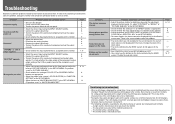
... color system ("COLOR SYSTEM") in "PICTURE SUB ADJ.." • Check whether the setting of COLOR OFF or SCREENS CHECK buttons are not malfunctions. • When a still image is not a malfunction. • Red spots, blue spots and green spots on the power of LCD displays, and not a problem. Change the input or the input signal. • The items controlled by using the adjustment knobs on the menu. • Set "CONTROL LOCK" in the SET-UP MENU to "OFF." • You cannot use...
... color system ("COLOR SYSTEM") in "PICTURE SUB ADJ.." • Check whether the setting of COLOR OFF or SCREENS CHECK buttons are not malfunctions. • When a still image is not a malfunction. • Red spots, blue spots and green spots on the power of LCD displays, and not a problem. Change the input or the input signal. • The items controlled by using the adjustment knobs on the menu. • Set "CONTROL LOCK" in the SET-UP MENU to "OFF." • You cannot use...
Instructions
Page 20
... of the INPUT SELECT lamps (COMPO./RGB, VIDEO1, VIDEO2) on the front control panel start flashing... 1 Check which lamps are flashing. 2 Press button to turn off (on standby) the monitor. 3 Turn off the power switch on the rear panel. 4 Disconnect the AC power cord from the wall outlet before turning on the monitor again. Troubleshooting (cont.) 7 Self-check program This monitor has a self-check function, which lamps were flashing. • If you turn on the screen. •...
... of the INPUT SELECT lamps (COMPO./RGB, VIDEO1, VIDEO2) on the front control panel start flashing... 1 Check which lamps are flashing. 2 Press button to turn off (on standby) the monitor. 3 Turn off the power switch on the rear panel. 4 Disconnect the AC power cord from the wall outlet before turning on the monitor again. Troubleshooting (cont.) 7 Self-check program This monitor has a self-check function, which lamps were flashing. • If you turn on the screen. •...
Instructions
Page 21
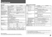
.... Specifications 7 General Model name Type Screen size Aspect ratio LCD panel Effective screen size Number of pixels displayed Number of colors displayed Viewing angle (TYP.) Panel brightness (TYP.) Contrast ratio (TYP.) Horizontal/vertical frequency (computer signal) Compliant video signal format Format Audio output Operating conditions Power requirements Rated current External dimensions (excluding protruding parts) Weight Accessories DT-V24L3DY DT-V20L3DY Multi format LCD monitor Type 24 wide format Type 20 wide format 16:10 24˝ wide, active matrix TFT 20˝ wide...
.... Specifications 7 General Model name Type Screen size Aspect ratio LCD panel Effective screen size Number of pixels displayed Number of colors displayed Viewing angle (TYP.) Panel brightness (TYP.) Contrast ratio (TYP.) Horizontal/vertical frequency (computer signal) Compliant video signal format Format Audio output Operating conditions Power requirements Rated current External dimensions (excluding protruding parts) Weight Accessories DT-V24L3DY DT-V20L3DY Multi format LCD monitor Type 24 wide format Type 20 wide format 16:10 24˝ wide, active matrix TFT 20˝ wide...

