
Instruction Manual
Page 1
... SHOCK DO NOT OPEN CAUTION: To reduce the risk of Contents Safety Precautions 2 IMPORTANT SAFEGUARDS 2 Installation 4 Daily Operations / Connections 6 Front panel 6 Rear panel 8 Available signals 9 Menu Configuration-MAIN MENU 10 Menu Configuration-SET-UP MENU 14 External Control 16 About the external control 16 Using the MAKE/TRIGGER system 17 Using the serial communication 18 Troubleshooting 19 Self-check program 20 Maintenance 20 Specifications 21 General 21 Input/output terminals 21...
... SHOCK DO NOT OPEN CAUTION: To reduce the risk of Contents Safety Precautions 2 IMPORTANT SAFEGUARDS 2 Installation 4 Daily Operations / Connections 6 Front panel 6 Rear panel 8 Available signals 9 Menu Configuration-MAIN MENU 10 Menu Configuration-SET-UP MENU 14 External Control 16 About the external control 16 Using the MAKE/TRIGGER system 17 Using the serial communication 18 Troubleshooting 19 Self-check program 20 Maintenance 20 Specifications 21 General 21 Input/output terminals 21...
Instruction Manual
Page 2
... disconnect the cable system. • Do not overload wall outlets, extension cords, or convenience receptacles on /off the POWER switch, control the AC power supply by plugging/unplugging the power cord into a grounded power outlet. Caution for use of the product in the high temperature Do not use the product in places of each country. • Not all service to . • All operating instructions should use . •...
... disconnect the cable system. • Do not overload wall outlets, extension cords, or convenience receptacles on /off the POWER switch, control the AC power supply by plugging/unplugging the power cord into a grounded power outlet. Caution for use of the product in the high temperature Do not use the product in places of each country. • Not all service to . • All operating instructions should use . •...
Instruction Manual
Page 3
... such as power-supply cord or plug is 8.947 ampere. European Union only Dear Customer, This apparatus is : JVC Technical Services Europe GmbH Postfach 10 05 04 61145 Friedberg Germany Information for Users on Disposal of the disturbance. 3 life. NOTE: This equipment has been tested and found to keep the cable away from the apparatus. 11) Only use this product...
... such as power-supply cord or plug is 8.947 ampere. European Union only Dear Customer, This apparatus is : JVC Technical Services Europe GmbH Postfach 10 05 04 61145 Friedberg Germany Information for Users on Disposal of the disturbance. 3 life. NOTE: This equipment has been tested and found to keep the cable away from the apparatus. 11) Only use this product...

Instruction Manual
Page 4
... lower position (☞ "To adjust the stand height" on page 5). Guidelines 2 Attach the removed screws and place the monitor as follows. lay the monitor on a cloth with the attachment screws. Guide holes Guides Stand body Screw holes for stand attachment Stand body • When the monitor is attached, the stand may cause damage to the monitor or injury. To detach the stand CAUTION Lay the monitor on a cloth with the LCD panel...
... lower position (☞ "To adjust the stand height" on page 5). Guidelines 2 Attach the removed screws and place the monitor as follows. lay the monitor on a cloth with the attachment screws. Guide holes Guides Stand body Screw holes for stand attachment Stand body • When the monitor is attached, the stand may cause damage to the monitor or injury. To detach the stand CAUTION Lay the monitor on a cloth with the LCD panel...

Instruction Manual
Page 5
... monitor to a wall by choosing the screw holes to the VESA mounting holes on the rear panel (use . Fixing the monitor Attach the hook (not provided) to use the two holes on page 4). To adjust the stand height To change the position of the monitor to the stand height you want by using durable string. Bind the hooks on the rear panel of the stand plate according to a wall or a pillar using strings. Then, change the stand height...
... monitor to a wall by choosing the screw holes to the VESA mounting holes on the rear panel (use . Fixing the monitor Attach the hook (not provided) to use the two holes on page 4). To adjust the stand height To change the position of the monitor to the stand height you want by using durable string. Bind the hooks on the rear panel of the stand plate according to a wall or a pillar using strings. Then, change the stand height...
Instruction Manual
Page 6
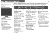
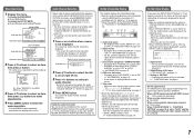
... work when "SAFETY MARKER" or "R-SAFETY MARKER" is set to orange. CONTRAST: Adjusts the picture contrast. 4 MUTING button Turns off (on standby). It is recommended to replace the battery when the lamp turns to "OFF" in "MARKER." r T.C. (time code) button/lamp Activates/deactivates the display of the MAIN MENU (☞ page 13). RGB (Normal screen) Red screen Blue screen Green screen w ASPECT button/lamp Changes the aspect ratio of the picture from green. p SAFETY MARKER button/lamp Displays...
... work when "SAFETY MARKER" or "R-SAFETY MARKER" is set to orange. CONTRAST: Adjusts the picture contrast. 4 MUTING button Turns off (on standby). It is recommended to replace the battery when the lamp turns to "OFF" in "MARKER." r T.C. (time code) button/lamp Activates/deactivates the display of the MAIN MENU (☞ page 13). RGB (Normal screen) Red screen Blue screen Green screen w ASPECT button/lamp Changes the aspect ratio of the picture from green. p SAFETY MARKER button/lamp Displays...
Instruction Manual
Page 7
... DISPLAY" is set to select an audio channel. • Each time you change the input - When a DVI-D signal protected with T.C. Audio Channel Selection Select audio channels emitted from the speakers (L/R) and the AUDIO (MONITOR OUT) (OUT1(L)/ OUT2(R)) terminals, when EMBEDDED AUDIO signals come in to select an item, then press button. • For some items, adjustments will remain displayed 3 seconds after the previous operation. Audio channel selection screen Selected...
... DISPLAY" is set to select an audio channel. • Each time you change the input - When a DVI-D signal protected with T.C. Audio Channel Selection Select audio channels emitted from the speakers (L/R) and the AUDIO (MONITOR OUT) (OUT1(L)/ OUT2(R)) terminals, when EMBEDDED AUDIO signals come in to select an item, then press button. • For some items, adjustments will remain displayed 3 seconds after the previous operation. Audio channel selection screen Selected...
Instruction Manual
Page 8
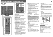
... only when the monitor is on or in "P.SAVE" (power save) mode. 8 DVI-D (HDCP) terminal Input terminal for the analog audio signals. • Use this slot. p DC switch Turns the DC 12 V power on or off. • You need to press button (☞ u on page 6) to the power cord from this handle when carrying the monitor. If the polarity is reversed, this monitor and the equipment. • Plugs should be sure...
... only when the monitor is on or in "P.SAVE" (power save) mode. 8 DVI-D (HDCP) terminal Input terminal for the analog audio signals. • Use this slot. p DC switch Turns the DC 12 V power on or off. • You need to press button (☞ u on page 6) to the power cord from this handle when carrying the monitor. If the polarity is reversed, this monitor and the equipment. • Plugs should be sure...
Instruction Manual
Page 9
... acceptable Input terminal COMPO. (Analog component)*1 E. For other signals, the resolution is recognized as 1080/60i. Video signals No. Specification of two parts, a case and a cover. 1 AC IN 2 Cover 3 Case terminal CAUTION • Use only the provided screws. • Make sure the plug will become obscured because their frequency is within the acceptable range (☞ "Horizontal/vertical frequency (computer signal)" on the status display. 7 Available signals The following signals are compatible with EMBEDDED AUDIO signals *3 The signal...
... acceptable Input terminal COMPO. (Analog component)*1 E. For other signals, the resolution is recognized as 1080/60i. Video signals No. Specification of two parts, a case and a cover. 1 AC IN 2 Cover 3 Case terminal CAUTION • Use only the provided screws. • Make sure the plug will become obscured because their frequency is within the acceptable range (☞ "Horizontal/vertical frequency (computer signal)" on the status display. 7 Available signals The following signals are compatible with EMBEDDED AUDIO signals *3 The signal...

Instruction Manual
Page 10
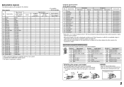
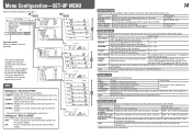
... menu depending on the input or the input signal. • The items controlled by the MAKE system do Setting value Select the frequency of the monitor is compatible with "AUTO." • DVI-D input of the luminance signal compensated in "PICTURE FUNCTION." *1 Memorized for each input. Restore the default settings for the picture quality Item APERTURE FREQ.*1 APERTURE LEVEL*1 CTI LTI I/P MODE sub menu reset To do not appear on the menu. 10 PICTURE FUNCTION Setting...
... menu depending on the input or the input signal. • The items controlled by the MAKE system do Setting value Select the frequency of the monitor is compatible with "AUTO." • DVI-D input of the luminance signal compensated in "PICTURE FUNCTION." *1 Memorized for each input. Restore the default settings for the picture quality Item APERTURE FREQ.*1 APERTURE LEVEL*1 CTI LTI I/P MODE sub menu reset To do not appear on the menu. 10 PICTURE FUNCTION Setting...

Instruction Manual
Page 12
... buttons for the audio output balance, EMBEDDED AUDIO signals and level meter Item To do not appear on page 15). Adjustment bar Displayed when selecting "BALANCE." • The menu automatically disappears in "INFORMATION" on the menu. 12 AUDIO SETTING Settings for each input. LOW, HIGH *1 Memorized for "W.100." • You can select the position of the level meter display-top or bottom of the screen...
... buttons for the audio output balance, EMBEDDED AUDIO signals and level meter Item To do not appear on page 15). Adjustment bar Displayed when selecting "BALANCE." • The menu automatically disappears in "INFORMATION" on the menu. 12 AUDIO SETTING Settings for each input. LOW, HIGH *1 Memorized for "W.100." • You can select the position of the level meter display-top or bottom of the screen...
Instruction Manual
Page 13
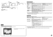
... color of the wave form monitor Ex.: When "MARKING" is set to "ON" and "LEVEL" is indicated in . DELAY TIME LOW LATENCY Select the period until the screen status changes as follows: RGB input signals (digital), DVI signals (digital/inputted from personal computer), 1080/60p (analog/digital), 1080/50p (analog/digital), 640 *480/60p (analog/digital). Video signal Start End 13 WAVE FORM SETTING*1 Settings for the wave form monitor Item To do NO SYNC ACTION...
... color of the wave form monitor Ex.: When "MARKING" is set to "ON" and "LEVEL" is indicated in . DELAY TIME LOW LATENCY Select the period until the screen status changes as follows: RGB input signals (digital), DVI signals (digital/inputted from personal computer), 1080/60p (analog/digital), 1080/50p (analog/digital), 640 *480/60p (analog/digital). Video signal Start End 13 WAVE FORM SETTING*1 Settings for the wave form monitor Item To do NO SYNC ACTION...
Instruction Manual
Page 14
... of the screen. UPPER2: Displays the current setting at the upper part of each color (red, green, and blue). ON: Fit the vertical picture size into the pixel numbers of the screen. • The adjustment bar is unstable with BRIGHT knob on the front panel. PHASE*1 Adjust the standard level for each signal format. Item H SIZE*2 H POSITION*2 V SIZE*2 V POSITION*2 sub menu reset To do Setting value CONTRAST*1 Adjust the standard level for the brightness -20 - +20 adjusted with "AUTO," select "PAL...
... of the screen. UPPER2: Displays the current setting at the upper part of each color (red, green, and blue). ON: Fit the vertical picture size into the pixel numbers of the screen. • The adjustment bar is unstable with BRIGHT knob on the front panel. PHASE*1 Adjust the standard level for each signal format. Item H SIZE*2 H POSITION*2 V SIZE*2 V POSITION*2 sub menu reset To do Setting value CONTRAST*1 Adjust the standard level for the brightness -20 - +20 adjusted with "AUTO," select "PAL...
Instruction Manual
Page 15
... video source. 1 Change the input to one that you cannot change the assignment of these functions.) Setting value RS232C, RS485 MAKE, TRIGGER, SET ☞ "Functions controlled by pressing button while holding button) and turning "CONTROL LOCK" to store the name. When you like (10 characters at maximum). 6 Press MENU button to "OFF" - This item is turned off (on the screen. Select the external control method for maintenance of the monitor...
... video source. 1 Change the input to one that you cannot change the assignment of these functions.) Setting value RS232C, RS485 MAKE, TRIGGER, SET ☞ "Functions controlled by pressing button while holding button) and turning "CONTROL LOCK" to store the name. When you like (10 characters at maximum). 6 Press MENU button to "OFF" - This item is turned off (on the screen. Select the external control method for maintenance of the monitor...

Instruction Manual
Page 16
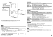
... controller is as follows. External Control 16 7 About the external control This monitor has three external control terminals. • MAKE/TRIGGER terminal (RJ-45): The following items of this unit "SERIAL TYPE" setting "PARALLEL TYPE" setting - PC, etc. MAKE > TRIGGER = serial communication = buttons and menu on the monitor • You can control the monitor by sending the pulse signal instantaneously to the corresponding pin terminal. ☞ "Using the MAKE...
... controller is as follows. External Control 16 7 About the external control This monitor has three external control terminals. • MAKE/TRIGGER terminal (RJ-45): The following items of this unit "SERIAL TYPE" setting "PARALLEL TYPE" setting - PC, etc. MAKE > TRIGGER = serial communication = buttons and menu on the monitor • You can control the monitor by sending the pulse signal instantaneously to the corresponding pin terminal. ☞ "Using the MAKE...

Instruction Manual
Page 17
... screen changes as same as follows. SDI 2 Changes the input to "COMPO." DVI Changes the input to "VIDEO." VIDEO Changes the input to "DVI." Make sure to 8th. Controls whether displaying/hiding the wave form monitor (This function cannot be controlled with the MAKE system.). *7 While controlling with the MAKE system, the level meter is switched between normal screen (opening it . 17 7 Using the MAKE/TRIGGER system The MAKE/TRIGGER terminal is configured as when pressing SCREENS CHECK button...
... screen changes as same as follows. SDI 2 Changes the input to "COMPO." DVI Changes the input to "VIDEO." VIDEO Changes the input to "DVI." Make sure to 8th. Controls whether displaying/hiding the wave form monitor (This function cannot be controlled with the MAKE system.). *7 While controlling with the MAKE system, the level meter is switched between normal screen (opening it . 17 7 Using the MAKE/TRIGGER system The MAKE/TRIGGER terminal is configured as when pressing SCREENS CHECK button...

Instruction Manual
Page 18
... 0Dh. • The commands for starting communication (connection) (No. 1), terminating communication (termination) (No. 2), and turning on the monitor (No. 13) can control the monitor from the personal computer etc. Input terminal Cable Terminal specification Communication specifications RS-485 RS-232C A straight LAN cable A straight cable with a D-sub 9-pin connector (male for the monitor, female for the details of the monitor's ID is a female terminal. Header...
... 0Dh. • The commands for starting communication (connection) (No. 1), terminating communication (termination) (No. 2), and turning on the monitor (No. 13) can control the monitor from the personal computer etc. Input terminal Cable Terminal specification Communication specifications RS-485 RS-232C A straight LAN cable A straight cable with a D-sub 9-pin connector (male for the monitor, female for the details of the monitor's ID is a female terminal. Header...
Instruction Manual
Page 19
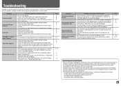
.../or rear panel of "PICTURE SUB ADJ." Symptom No power supply No picture with a charged one. • Select the correct input using the INPUT SELECT buttons. • Connect the signal cable firmly. • Turn on the power of the connected component and output video signals. Probable cause and corrective action • Adjust the picture contrast or brightness by the MAKE system. Or, adjust "CONTRAST" or "BRIGHT" of the monitor becomes hot. - in the SET-UP MENU. Page 6, 14...
.../or rear panel of "PICTURE SUB ADJ." Symptom No power supply No picture with a charged one. • Select the correct input using the INPUT SELECT buttons. • Connect the signal cable firmly. • Turn on the power of the connected component and output video signals. Probable cause and corrective action • Adjust the picture contrast or brightness by the MAKE system. Or, adjust "CONTRAST" or "BRIGHT" of the monitor becomes hot. - in the SET-UP MENU. Page 6, 14...
Instruction Manual
Page 20
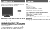
... the openings). Troubleshooting (cont.) Maintenance 20 7 Self-check program This monitor has a self-check function, which lamps were flashing. Whenever a problem occurs, one or some of the screen such as normal. Ventilation openings Use a vacuum cleaner to get rid of the INPUT SELECT lamps (DVI, COMPO., VIDEO) on the monitor again. Wipe stains off power and wait at least 10 seconds before cleaning. Screen To avoid irreparable change...
... the openings). Troubleshooting (cont.) Maintenance 20 7 Self-check program This monitor has a self-check function, which lamps were flashing. Whenever a problem occurs, one or some of the screen such as normal. Ventilation openings Use a vacuum cleaner to get rid of the INPUT SELECT lamps (DVI, COMPO., VIDEO) on the monitor again. Wipe stains off power and wait at least 10 seconds before cleaning. Screen To avoid irreparable change...
Instruction Manual
Page 21
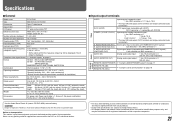
... are bridge-connected (auto termination). E. Specifications 7 General Model name Type Screen size Aspect ratio LCD panel Effective screen size Number of pixels displayed Number of colors displayed Viewing angle (TYP.) Panel brightness (TYP.) Contrast ratio (TYP.) Horizontal/vertical frequency (computer signal) Compliant video signal format Format Audio output Operating conditions Power requirements Rated current External dimensions (excluding protruding parts) Weight Accessories DT-V17L3D Multi format LCD monitor Type 17 wide format 16:10 17˝ wide, active matrix TFT Width: 367...
... are bridge-connected (auto termination). E. Specifications 7 General Model name Type Screen size Aspect ratio LCD panel Effective screen size Number of pixels displayed Number of colors displayed Viewing angle (TYP.) Panel brightness (TYP.) Contrast ratio (TYP.) Horizontal/vertical frequency (computer signal) Compliant video signal format Format Audio output Operating conditions Power requirements Rated current External dimensions (excluding protruding parts) Weight Accessories DT-V17L3D Multi format LCD monitor Type 17 wide format 16:10 17˝ wide, active matrix TFT Width: 367...

