Instruction Manual
Page 1
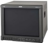
Retain this information for future reference. LCT1424-001A Model No. : DT-V1910CG/DT-V1710CG Serial No. : MUTING VOLUME UNDER DEGAUSS SCAN PULSE CROSS COLOR OFF MENU SCREENS ASPECT AREA CHECK MARKER SLOT 1 SLOT 2 SLOT 3 A B C D E F INPUT SELECT POWER The illustration shows the DT-V1910CG with provided wide mask attached. which is located on the rear of the cabinet. MULTI-FORMAT MONITOR DT-V1910CG DT-V1710CG INSTRUCTIONS For Customer Use: Enter below the Serial No.
Retain this information for future reference. LCT1424-001A Model No. : DT-V1910CG/DT-V1710CG Serial No. : MUTING VOLUME UNDER DEGAUSS SCAN PULSE CROSS COLOR OFF MENU SCREENS ASPECT AREA CHECK MARKER SLOT 1 SLOT 2 SLOT 3 A B C D E F INPUT SELECT POWER The illustration shows the DT-V1910CG with provided wide mask attached. which is located on the rear of the cabinet. MULTI-FORMAT MONITOR DT-V1910CG DT-V1710CG INSTRUCTIONS For Customer Use: Enter below the Serial No.
Instruction Manual
Page 2
... protection against harmful interference when the equipment is excessively dirty, use a magnet eraser to operate the equipment. Do not apply... outside. only) CAUTION: Changes or modification not approved by JVC could deform the cabinet or cause the performance of internal components... the monitor, be fully aware of all explanations (except where noted) refer to the DT-V1910CG and DT-V1710CG with...monitor. Dangerous high voltages are no longer be input to this monitor to high temperatures. Never try to satisfy FCC rule. WARNING : THIS APPARATUS MUST BE EARTHED. This monitor...
... protection against harmful interference when the equipment is excessively dirty, use a magnet eraser to operate the equipment. Do not apply... outside. only) CAUTION: Changes or modification not approved by JVC could deform the cabinet or cause the performance of internal components... the monitor, be fully aware of all explanations (except where noted) refer to the DT-V1910CG and DT-V1710CG with...monitor. Dangerous high voltages are no longer be input to this monitor to high temperatures. Never try to satisfy FCC rule. WARNING : THIS APPARATUS MUST BE EARTHED. This monitor...
Instruction Manual
Page 3
... so may cause malfunction, electric shock or fire. Power cord Power supply voltage : AC 120 V Countries : U.S.A. Note for AC 230 V. Use only the power cord designated to the following power supply voltage and countries. and Canada AC 230 V European countries AC 230 V United Kingdom Warning...: ● Do not use only a correctly rated approved type, re-fit the fuse cover. (Consult your dealer or qualified service personnel.) How to replace the fuse...
... so may cause malfunction, electric shock or fire. Power cord Power supply voltage : AC 120 V Countries : U.S.A. Note for AC 230 V. Use only the power cord designated to the following power supply voltage and countries. and Canada AC 230 V European countries AC 230 V United Kingdom Warning...: ● Do not use only a correctly rated approved type, re-fit the fuse cover. (Consult your dealer or qualified service personnel.) How to replace the fuse...
Instruction Manual
Page 4
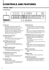
.... • When the button is pressed, the next lowest channel is selected. NOTES: Switchable channels correspond with the group selected in the "E.AUDIO GROUP" of DT-V1910CG shown) MUTING VOLUME UNDER DEGAUSS SCAN PULSE CROSS COLOR OFF MENU SCREENS ASPECT AREA CHECK MARKER SLOT 1 SLOT 2 SLOT 3 A B C D E F INPUT SELECT 6 9... the screen, this button while the VOLUME bar is installed. 9 Menu select buttons Selects menu screen items or set the color, use TALLY SELECT in the "FUNCTION SETTING" setup menu or MAKE/TRIGGER in the REMOTE (external control) terminal setup menu.
.... • When the button is pressed, the next lowest channel is selected. NOTES: Switchable channels correspond with the group selected in the "E.AUDIO GROUP" of DT-V1910CG shown) MUTING VOLUME UNDER DEGAUSS SCAN PULSE CROSS COLOR OFF MENU SCREENS ASPECT AREA CHECK MARKER SLOT 1 SLOT 2 SLOT 3 A B C D E F INPUT SELECT 6 9... the screen, this button while the VOLUME bar is installed. 9 Menu select buttons Selects menu screen items or set the color, use TALLY SELECT in the "FUNCTION SETTING" setup menu or MAKE/TRIGGER in the REMOTE (external control) terminal setup menu.

Instruction Manual
Page 5
...the screen automatically brightens to make it easier to "SYNC SELECT" on the current input selection and the monitor settings. NOTE: This function is restored. • Use this function to confirm the noise in the slot corresponding to ON, the button lights. Only the ... selected. • "VIDEO(Y/C)" is displayed when S-video is input from one of each function in the monitor's card slots (SLOT1 - INPUT C Selected input VIDEO Input card status (*1) NTSC Signal format (*2) HIGH Setting of "COLOR TEMP." (*3) EXT SYNC External synchronization (*4) *1 Notes • "NO SLOT" is ...
...the screen automatically brightens to make it easier to "SYNC SELECT" on the current input selection and the monitor settings. NOTE: This function is restored. • Use this function to confirm the noise in the slot corresponding to ON, the button lights. Only the ... selected. • "VIDEO(Y/C)" is displayed when S-video is input from one of each function in the monitor's card slots (SLOT1 - INPUT C Selected input VIDEO Input card status (*1) NTSC Signal format (*2) HIGH Setting of "COLOR TEMP." (*3) EXT SYNC External synchronization (*4) *1 Notes • "NO SLOT" is ...

Instruction Manual
Page 7
To use these terminals, set "SYNC SELECT" to the connection terminal of your Multi-Format Monitor. Ⅵ VIDEO INPUT CARD (IF-C01PNG) VIDEO 1 IN OUT VIDEO 2 1 IN OUT Y/C IN 2 EXT.SYNC 3 IN OUT AUDIO 1 IN OUT 4 AUDIO 2 5 Ⅵ Compatible signal..., 1080/60i, 1080/24psF 1 Component/RGB signal input/output terminals Input (IN) and output (OUT) terminals for the composite video signals of your Multi-Format Monitor. 7 Refer to "SYNC SELECT" on page 19 for more information. 3 Audio input/output terminals Input (IN) and output (OUT) terminals for the S-video ...
To use these terminals, set "SYNC SELECT" to the connection terminal of your Multi-Format Monitor. Ⅵ VIDEO INPUT CARD (IF-C01PNG) VIDEO 1 IN OUT VIDEO 2 1 IN OUT Y/C IN 2 EXT.SYNC 3 IN OUT AUDIO 1 IN OUT 4 AUDIO 2 5 Ⅵ Compatible signal..., 1080/60i, 1080/24psF 1 Component/RGB signal input/output terminals Input (IN) and output (OUT) terminals for the composite video signals of your Multi-Format Monitor. 7 Refer to "SYNC SELECT" on page 19 for more information. 3 Audio input/output terminals Input (IN) and output (OUT) terminals for the S-video ...
Instruction Manual
Page 11
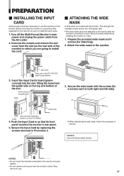
...to both right and left side). Secure the wide mask with the monitor. Secure the Input Card by replacing the screws removed in a rack. 1. Caution: Use only the provided screws. Mount the wide mask before installing the monitor in Procedure 2. Prepare the provided wide mask and 4 screws (for ... the Input Card's board (greencolored) into the slot, fitting the board into the guide rails on the rear side of the DT-V1910CG Multi-Format Monitor 3. Push the Input Card in reverse. SLOT1 SLOT2 SLOT3 Guide rails Input card (the illustration Knob shown is provided with the screws...
...to both right and left side). Secure the wide mask with the monitor. Secure the Input Card by replacing the screws removed in a rack. 1. Caution: Use only the provided screws. Mount the wide mask before installing the monitor in Procedure 2. Prepare the provided wide mask and 4 screws (for ... the Input Card's board (greencolored) into the slot, fitting the board into the guide rails on the rear side of the DT-V1910CG Multi-Format Monitor 3. Push the Input Card in reverse. SLOT1 SLOT2 SLOT3 Guide rails Input card (the illustration Knob shown is provided with the screws...
Instruction Manual
Page 12
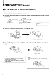
... to open the cover. 12 Attach the Power Cord Holder cover to make sure the plug doesn't pull out after the cover is attached. Caution: Use only the provided screws. Caution: • A different plug shape will result in the cover being attached to a different position. • Check to the AC power...; The provided Power Cord Holder prevents accidental disconnection of the AC power cord from the AC inlet. • The Power Cord Holder consists of the monitor with the case. Attach the Power Cord Holder case to the AC inlet on the back of two parts;
... to open the cover. 12 Attach the Power Cord Holder cover to make sure the plug doesn't pull out after the cover is attached. Caution: Use only the provided screws. Caution: • A different plug shape will result in the cover being attached to a different position. • Check to the AC power...; The provided Power Cord Holder prevents accidental disconnection of the AC power cord from the AC inlet. • The Power Cord Holder consists of the monitor with the case. Attach the Power Cord Holder case to the AC inlet on the back of two parts;
Instruction Manual
Page 13
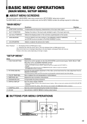
...(setup menu screen). Not displayed when an RGB signal is installed.) Sets the control lock preventing the monitor from misuse. Position of the picture. The MAIN MENU contains the functions normally used . * Sets the AUTO INPUT function ON/OFF. (When an input card compliant with EMBEDDED AUDIO ... COLOR SYSTEM, synchronized signal, RUSH DELAY TIME, tally lamp colors, and MAKE/TRIGGER terminal. * Checks the amount of time that the monitor has been used , and the SETUP MENU contains the settings required for the EMBEDDED AUDIO. (When an input card compliant with AUTO INPUT is installed.)...
...(setup menu screen). Not displayed when an RGB signal is installed.) Sets the control lock preventing the monitor from misuse. Position of the picture. The MAIN MENU contains the functions normally used . * Sets the AUTO INPUT function ON/OFF. (When an input card compliant with EMBEDDED AUDIO ... COLOR SYSTEM, synchronized signal, RUSH DELAY TIME, tally lamp colors, and MAKE/TRIGGER terminal. * Checks the amount of time that the monitor has been used , and the SETUP MENU contains the settings required for the EMBEDDED AUDIO. (When an input card compliant with AUTO INPUT is installed.)...
Instruction Manual
Page 14
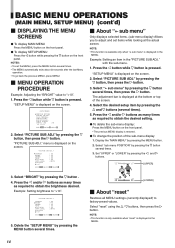
... last Menu operation. • To go back the previous MENU, press MENU. Ⅵ MENU OPERATION PROCEDURE Example: Adjusting the "BRIGHT" value to "+10". Select "reset" using the / buttons, then press the button. SIZE/POSI.ADJ. NOTE: • This function is available only when " sub menu" is displayed in the "PICTURE SUB...
... last Menu operation. • To go back the previous MENU, press MENU. Ⅵ MENU OPERATION PROCEDURE Example: Adjusting the "BRIGHT" value to "+10". Select "reset" using the / buttons, then press the button. SIZE/POSI.ADJ. NOTE: • This function is available only when " sub menu" is displayed in the "PICTURE SUB...
Instruction Manual
Page 15
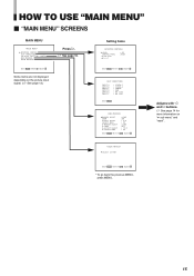
Setting Items LEVEL CONTROL FREQ. SELECT :ITU601 EXIT:MENU ADJUST:- + SELECT: * To go back the previous MENU, press MENU. 15 sub menu reset : 00 :HIGH EXIT:MENU ADJUST:- + SELECT: INPUT A INPUT B INPUT C INPUT D INPUT E INPUT F : VIDEO-1 : VIDEO-2 : COMPO. : RGB : NO SLOT : NO SLOT EXIT:...2668; See page 14 for more information on the picture input signal. (੬ See page 13.) Press . ੬ See page 16. HOW TO USE "MAIN MENU" Ⅵ "MAIN MENU" SCREENS MAIN MENU APERTURE CONTROL SLOT CONDITION sub menu POSITION :LOWER AREA MARKER. COLOR MATRIX EXIT:MENU ENTER:+ ...
Setting Items LEVEL CONTROL FREQ. SELECT :ITU601 EXIT:MENU ADJUST:- + SELECT: * To go back the previous MENU, press MENU. 15 sub menu reset : 00 :HIGH EXIT:MENU ADJUST:- + SELECT: INPUT A INPUT B INPUT C INPUT D INPUT E INPUT F : VIDEO-1 : VIDEO-2 : COMPO. : RGB : NO SLOT : NO SLOT EXIT:...2668; See page 14 for more information on the picture input signal. (੬ See page 13.) Press . ੬ See page 16. HOW TO USE "MAIN MENU" Ⅵ "MAIN MENU" SCREENS MAIN MENU APERTURE CONTROL SLOT CONDITION sub menu POSITION :LOWER AREA MARKER. COLOR MATRIX EXIT:MENU ENTER:+ ...
Instruction Manual
Page 16
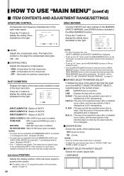
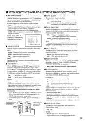
...: MENU ADJUST:- + SELECT: Ⅵ LEVEL Adjusts the compensate value. HIGH: Compensates the high frequencies. COMP./RGB : With Component/RGB input card is installed. SDI1/SDI2 : With SDI input card is installed. LINE : Displays the area with ...transparency. BLK.+L : The area of the specified screen ratio is indicated by an outline, and the area outside of the input card slots. HOW TO USE "MAIN MENU" (cont'd) Ⅵ ITEM CONTENTS AND ADJUSTMENT RANGE/SETTINGS APERTURE CONTROL AREA MARKER: Compensates the frequency characteristics of the specified screen ratio is ...
...: MENU ADJUST:- + SELECT: Ⅵ LEVEL Adjusts the compensate value. HIGH: Compensates the high frequencies. COMP./RGB : With Component/RGB input card is installed. SDI1/SDI2 : With SDI input card is installed. LINE : Displays the area with ...transparency. BLK.+L : The area of the specified screen ratio is indicated by an outline, and the area outside of the input card slots. HOW TO USE "MAIN MENU" (cont'd) Ⅵ ITEM CONTENTS AND ADJUSTMENT RANGE/SETTINGS APERTURE CONTROL AREA MARKER: Compensates the frequency characteristics of the specified screen ratio is ...
Instruction Manual
Page 18
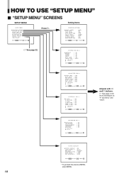
... : 00 EXIT:MENU ADJUST:- + SELECT: 18 STATUS DISPLAY LEVEL METER ch BAR TYPE REFERENCE LEVEL OVER LEVEL BAR BRIGHTNESS :ON :31 24 :3COLORS :-20dB :-4dB :HIGH EXIT:MENU ADJUST:- + SELECT: * To go back the previous MENU, press MENU. STATUS DISPLAY CONTROL LOCK all reset :ON EXIT:MENU ENTER:+ SELECT: Press . DISTORTION... REMOTE SYSTEM E.AUDIO GROUP HOUR METER X100 :AUTO :ON :INT. :STD. :GREEN :MAKE :1G :000 EXIT:MENU ADJUST:- + SELECT: ੬ See page 22. HOW TO USE "SETUP MENU" Ⅵ "SETUP MENU" SCREENS SETUP MENU Setting Items FUNCTION SETTING PICTURE SUB ADJ.
... : 00 EXIT:MENU ADJUST:- + SELECT: 18 STATUS DISPLAY LEVEL METER ch BAR TYPE REFERENCE LEVEL OVER LEVEL BAR BRIGHTNESS :ON :31 24 :3COLORS :-20dB :-4dB :HIGH EXIT:MENU ADJUST:- + SELECT: * To go back the previous MENU, press MENU. STATUS DISPLAY CONTROL LOCK all reset :ON EXIT:MENU ENTER:+ SELECT: Press . DISTORTION... REMOTE SYSTEM E.AUDIO GROUP HOUR METER X100 :AUTO :ON :INT. :STD. :GREEN :MAKE :1G :000 EXIT:MENU ADJUST:- + SELECT: ੬ See page 22. HOW TO USE "SETUP MENU" Ⅵ "SETUP MENU" SCREENS SETUP MENU Setting Items FUNCTION SETTING PICTURE SUB ADJ.
Instruction Manual
Page 19
... units. • 000 ~ 655 NOTES: • When the timer passes 655, it is recommended to apply SLOW to some of the monitors to the monitor's circuits (excluding the micro computers) starts after the power switch is pressed. Refer to the each channel's level will be. (Each channel's... the COLOR SYSTEM, synchronized signal, RUSH DELAY TIME, tally lamp colors, and MAKE/TRIGGER terminal. • Checks the amount of time that the monitor has been used . • "INPUT SELECT ERROR" is displayed for approx. 3 seconds when different signal cables are connected to each INPUT A and INPUT C ...
... units. • 000 ~ 655 NOTES: • When the timer passes 655, it is recommended to apply SLOW to some of the monitors to the monitor's circuits (excluding the micro computers) starts after the power switch is pressed. Refer to the each channel's level will be. (Each channel's... the COLOR SYSTEM, synchronized signal, RUSH DELAY TIME, tally lamp colors, and MAKE/TRIGGER terminal. • Checks the amount of time that the monitor has been used . • "INPUT SELECT ERROR" is displayed for approx. 3 seconds when different signal cables are connected to each INPUT A and INPUT C ...
Instruction Manual
Page 20
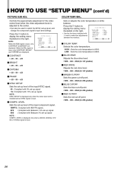
Controls the approximate adjustment of the video control level when the video adjustment knob is adjusted to the center. • Can also be used to make fine adjustments between the monitors. CONTRAST BRIGHT CHROMA PHASE NTSC SETUP COMPO.LEVEL sub menu reset : 00 : 00 : 00 : 00 : 00 :SMPTE EXIT: MENU...8549; PHASE • -20 ~ 00 ~ +20 Ⅵ NTSC SETUP Sets the set-up level of the input component signal. COLOR TEMP./BAL. COLOR TEMP. HIGH : Sets the color temperature to 6500. Ⅵ BLUE DRIVE Adjusts the blue drive level. • MIN ~ 000 ~ MAX (in 127 grades) Ⅵ ...
Controls the approximate adjustment of the video control level when the video adjustment knob is adjusted to the center. • Can also be used to make fine adjustments between the monitors. CONTRAST BRIGHT CHROMA PHASE NTSC SETUP COMPO.LEVEL sub menu reset : 00 : 00 : 00 : 00 : 00 :SMPTE EXIT: MENU...8549; PHASE • -20 ~ 00 ~ +20 Ⅵ NTSC SETUP Sets the set-up level of the input component signal. COLOR TEMP./BAL. COLOR TEMP. HIGH : Sets the color temperature to 6500. Ⅵ BLUE DRIVE Adjusts the blue drive level. • MIN ~ 000 ~ MAX (in 127 grades) Ⅵ ...
Instruction Manual
Page 22
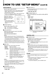
...menu screen operations). OFF : Enables normal operations. ON : The information is not displayed. Ⅵ LEVEL METER ch Selects the audio channels used in the "REFERENCE LEVEL" is displayed. 2. OFF : The information is displayed. warning to CONTROL LOCK and cannot be moved. Also selects...LEVEL OVER LEVEL BAR BRIGHTNESS : ON :31•24 :3COLORS : -20dB : -4dB : HIGH EXIT: MENU ADJUST:- + SELECT: Ⅵ STATUS DISPLAY Sets the status display ON or OFF. HOW TO USE "SETUP MENU" (cont'd) STATUS DISPLAY Sets the status display ON/OFF. * Switches the display...
...menu screen operations). OFF : Enables normal operations. ON : The information is not displayed. Ⅵ LEVEL METER ch Selects the audio channels used in the "REFERENCE LEVEL" is displayed. 2. OFF : The information is displayed. warning to CONTROL LOCK and cannot be moved. Also selects...LEVEL OVER LEVEL BAR BRIGHTNESS : ON :31•24 :3COLORS : -20dB : -4dB : HIGH EXIT: MENU ADJUST:- + SELECT: Ⅵ STATUS DISPLAY Sets the status display ON or OFF. HOW TO USE "SETUP MENU" (cont'd) STATUS DISPLAY Sets the status display ON/OFF. * Switches the display...
Instruction Manual
Page 23
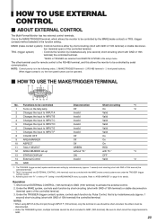
... controls each function by Pulse Control, that is possible. When trigger contact is the MAKE/TRIGGER terminal, which allows the monitor to GND (15th terminal). NOTES: • When using INPUT A (the 2nd pin) through INPUT F (7th terminal), only the terminal in the following order; 1 MAKE...controlled terminal. Be sure to short-circuit the single terminal to activate the external control. 2. HOW TO USE EXTERNAL CONTROL Ⅵ ABOUT EXTERNAL CONTROL The Multi-Format Monitor has two external control terminals. TRG. (trigger system) : Controls the function by short-circuiting (short ...
... controls each function by Pulse Control, that is possible. When trigger contact is the MAKE/TRIGGER terminal, which allows the monitor to GND (15th terminal). NOTES: • When using INPUT A (the 2nd pin) through INPUT F (7th terminal), only the terminal in the following order; 1 MAKE...controlled terminal. Be sure to short-circuit the single terminal to activate the external control. 2. HOW TO USE EXTERNAL CONTROL Ⅵ ABOUT EXTERNAL CONTROL The Multi-Format Monitor has two external control terminals. TRG. (trigger system) : Controls the function by short-circuiting (short ...
Instruction Manual
Page 24
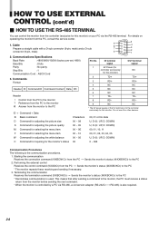
... : ASCII Cord 3. Control from the PC [ Sends the monitor's status (@XXBOKCr) to the monitor ? TD- 8 RD- Do not use it for the monitor's status 00 0 ~ 655 Communication Procedures The following is for the controller exclusively for this monitor) TD+ RD+ NC OUT terminal signal NC TD+ RD+...1 2 3 4 IN terminal signal 5V Power (for controller exclusively for this monitor. HOW TO USE EXTERNAL CONTROL (cont'd) Ⅵ HOW TO USE THE RS-485 TERMINAL You can control the monitor from the controller (exclusive for this monitor) or your PC via RS-485, a conversion adapter (RS-232Cp[RS-485)...
... : ASCII Cord 3. Control from the PC [ Sends the monitor's status (@XXBOKCr) to the monitor ? TD- 8 RD- Do not use it for the monitor's status 00 0 ~ 655 Communication Procedures The following is for the controller exclusively for this monitor) TD+ RD+ NC OUT terminal signal NC TD+ RD+...1 2 3 4 IN terminal signal 5V Power (for controller exclusively for this monitor. HOW TO USE EXTERNAL CONTROL (cont'd) Ⅵ HOW TO USE THE RS-485 TERMINAL You can control the monitor from the controller (exclusive for this monitor) or your PC via RS-485, a conversion adapter (RS-232Cp[RS-485)...
Instruction Manual
Page 25
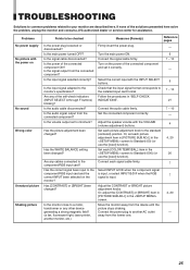
... the component signal is input, or select INPUT B/D/F when the RGB 7 signal is input. Connect each picture adjustment knob to Standard (000) (or use the [reset] function). Is the volume output set each [COLOR TEMP./BAL.] item in "SELF-CHECK INDICATIONS". 5 7 ~ 10 27 Connect the audio...the audio cable disconnected? Is the main power turned OFF? Is the power of the solutions presented here solve the problem, unplug the monitor and consult a JVC-authorized dealer or service center for assistance. Are any of the connected component and set it correctly. 6 7 ~ 10 - Check ...
... the component signal is input, or select INPUT B/D/F when the RGB 7 signal is input. Connect each picture adjustment knob to Standard (000) (or use the [reset] function). Is the volume output set each [COLOR TEMP./BAL.] item in "SELF-CHECK INDICATIONS". 5 7 ~ 10 27 Connect the audio...the audio cable disconnected? Is the main power turned OFF? Is the power of the solutions presented here solve the problem, unplug the monitor and consult a JVC-authorized dealer or service center for assistance. Are any of the connected component and set it correctly. 6 7 ~ 10 - Check ...
Instruction Manual
Page 26
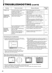
... harmful. ● The monitor emits a strange sound when the room temperature changes suddenly. Set the CONTROL LOCK function to mutual interference; Change the setting of the image on the screen if the aperture grill is tilted as a result of DT-V1910CG shown) ● ...two or more than 30 minutes for composing the monitor. Damper line MUTING VOLUME UNDER DEGAUSS SCAN PULSE CROSS COLOR OFF MENU SCREENS ASPECT AREA CHECK MARKER SLOT 1 SLOT 2 SLOT 3 A B C D E F INPUT SELECT POWER (Front view of being used .) The screen might appear as brownish white. This...
... harmful. ● The monitor emits a strange sound when the room temperature changes suddenly. Set the CONTROL LOCK function to mutual interference; Change the setting of the image on the screen if the aperture grill is tilted as a result of DT-V1910CG shown) ● ...two or more than 30 minutes for composing the monitor. Damper line MUTING VOLUME UNDER DEGAUSS SCAN PULSE CROSS COLOR OFF MENU SCREENS ASPECT AREA CHECK MARKER SLOT 1 SLOT 2 SLOT 3 A B C D E F INPUT SELECT POWER (Front view of being used .) The screen might appear as brownish white. This...